135
Processing and Application of Ceramics 4 [3] (2010) 135–145Aerosol route in processing of nanostructured phosphor materials
#Katarina Marinković
1, Luz S.Gomez
2, Maria E. Rabanal
2, Lidija Mančić
1, Olivera Milošević
1,*1Institute of Technical Sciences of Serbian Academy of Sciences and Arts, K. Mihailova 35/IV, 11000 Belgrade, Serbia
2Universidad Carlos III de Madrid, Avda. de la Universidad 30, Leganes, Madrid, Spain Received 23 February 2010; received in revised form 17 May 2010; accepted 23 August 2010
Abstract
Among the methods currently used for nanophase processing, synthesis through dispersion phase (aerosol) enables generation of ultraine powders with controlled stoichiometry. It represents a “bottom-up” chemical approach that provides control over a variety of important parameters enabling the formation of either amor -phous, nanocrystalline or metastable phases. Particularly, the opportunities of the hot wall aerosol synthesis, i.e. spray pyrolysis, for the generation of ultraine phosphor particles with uniformly distributed components, nano-clustered inner structure and luminescence properties is demonstrated in following systems: Gd2O3:Eu, Y2O3:Eu, (Y1-xGdx):Eu and Y3Al5O12:Ce, highlighting the research activities in the Institute of Technical Sci-ences of SASA, Serbia and the University Carlos III, Madrid, Spain in the framework of COST 539 Action. Keywords: aerosol, nanoparticles, synthesis, phosphors, luminescence
I. Introduction
The ield of nanoscience and nanotechnology has an exciting progress in recent years, particularly regarding the control synthesis of ultraine particles or nanoparti -cles that might have a great potential for use in solid-state functional materials and devices, like phosphors, sensors, catalysts, drug delivery carriers etc. [1] The key points important for the future research of nano-phased materials represent the ability for further im-provement of material properties through nanostruc-turing and fundamental research of structure-properties relationship. The chemical synthesis routes, like liquid precipitation, sol-gel, hydrothermal methods or synthe-sis through aerosol, offer many advantages over con-ventional procedures for nanoscaled materials process-ing. Since the precursors are mixed at the molecular level in a solution, a high degree of structural homo-geneity is achievable; doping is effective; surface area of powder produced is very high, leading to lower pro-cessing temperature. Compared to other propro-cessing
techniques, powder synthesis through aerosol routes represents a simple method for production of oxide, non-oxide, metal and composite powders of complex composition, either in amorphous, crystalline or nano-crystalline state [2]. Solution chemistry approaches of-fer design of materials at the molecular level, spherical particle morphology with full or hollow spheres, hav-ing narrow particle size distribution and a very homo-geneous composition. Depending on how the thermal energy is provided to the precursors, affecting the most important particle formation parameters: residence time and temperature distribution, one can distinguish: hot-wall processing - spray pyrolysis, lame synthesis, self sustaining lame reactors and self combustion aerosol synthesis [3]. Hot-wall aerosol synthesis is based on the formation of aerosols of precursor solutions and control over the aerosol decomposition in a high temperature tubular low reactor through the successive processes of droplet evaporation, drying, solute precipitation and decomposition. Since the heterogeneous gas/liquid-sol-id reaction occurs in a dispersed system-aerosol at the level of few micrometers sized droplets, composition-al segregation is prevented and high heating rates (20– 300°C/s) could be achieved [2]. During decomposi-tion, the aerosol droplets undergo evaporation/drying, precipitation and thermolysis in a single-step process. # These results were partially published in a review article
“Aerosol route in processing of nanostructured functional materials “, KONA 27 (2009) 84–106
* Corresponding author: tel: +381 11 2636994
136
K. Marinković et al. / Processing and Application of Ceramics 4 [3] (2010) 135–145
Consequently, spherical, solid, agglomerate-free, either submicronic, nanostructuredor nanoscaled particles are obtained through the mechanisms of primary nanopar-ticles coalescence, collision and sintering. Schematic of the hot-wall aerosol synthesis routes is presented in Fig. 1. Synthesis I refers to the chemical synthesis and lution preparation that could be in the form of true so-lutions, colloids or emulsions. The modiication of the chemistry of the solution, i.e. additives like glycine, urea, sucrose etc. alters the morphology of the parti-cles derived as well as the particle size, size distribution and agglomeration state. The precursors and precursor’s chemistry are usually characterized for their physico-chemical properties since there is a strong relationship between them and the droplet/particle size [4]. Liquid atomization and aerosol formation occur for the certain values of the acoustic waves amplitude formed by ul-trasonic beam (100 KHz–10 MHz). Depending on the atomization technique, either monodispersed or poly-dispersed droplets could be generated. More about the manner of aerosol formation and equations that gov-ern droplets and particle size distribution was published previously [5]. The generated aerosol is carried out by the lowing gas stream into high-temperature tubular low reactor. During the main process, denoted as Syn -thesis II, aerosol droplets undergo evaporation, drying and solute precipitation in a single-step process caused by the mechanisms of heat and mass transfer inside the droplets and between the droplets and surrounding gas. Such mechanism enables high surface reaction, solution
stoichiometric retention as well as segregation suppres-sion to the droplet scale.
The primary particles arise through the thermal-ly induced processes of nuclei formation, collision and coalescence, resulting in inal spherical arrange -ment called “secondary particles”. The secondary par-ticle size and size distribution are mainly inluenced by the properties of aerosol generator and precursor solu-tions. Primary particles, that represent either crystal-lites or block-mosaic assembles could coalesced entire-ly or densiied with existing nanoporosity inluencing the morphology and size of secondary particles. Pro-cessing of nanoparticles can be achieved directly from nano-sized droplets, from very dilute solutions or from submicronic secondary particles, that offer a compos-ite nanograin particle structure [6,7]. Salt assisted spray pyrolysis (SAD) enable releasing the nano-scaled pri-mary particles by modiication the solution chemistry and preventing formation of aggregated primary parti-cles into the secondary partiparti-cles [8].
The potentials of the aerosol routes for making sol-id-states structures at the nano-size level are virtually unlimited, providing possibilities for their unique appli-cations in electronics, optoelectronics, catalysis, energy conversion systems, drug delivery etc. In the framework of our recent research, the synthesis of ine particles have been established for following materials: ZnO [9], ZnO-Pt(IV) [10], ZnO- Ru(III) [11] and ZnO-Cr2O3 spi-nel phase [7]. Achievements attained in the synthesis of phosphor materials [5,12–25], will be reviewed here.
137
K. Marinković et al. / Processing and Application of Ceramics 4 [3] (2010) 135–145
II. Phosphors
Phosphors represent inorganic crystal structures ca-pable of emitting deinite quantities of radiation with -in visible and/or ultraviolet spectrum as a result of exci-tation by an external energy source such as electron or a photon beam [26,27]. Such properties of these mate-rials are an outcome from the atomic state interactions that occur between luminescent centres and the host lat-tice material after the excitation. Rare earth ions (Eu2+,
Eu3+, Ce3+, Tm3+, Tb3+, Nd3+) and transition metal ions
(Cr3+, Mn2+) are commonly used as luminescent centres
[28]. The important properties that luminescent materi-als should have are brightness, spectral energy distribu-tion and decay time [29].
Gd2O3:Eu 3+
Gadolinia doped with europium has been used in several applications for display devices as effective red phosphor material having improved stability in high vac-uum and the absence of corrosive gas emissions under electron bombardment [30]. As part of a program to de-velop high grade phosphor particles, spherical in shape, agglomerated-free and with a narrow size distribution, nanostructured, spherical Gd2O3:Eu3+ phosphor particles
sizing bellow 800 nm were synthesized from ultrasoni-cally generated common nitrates solutions, Fig. 2.
The particle inner structure (Fig. 2b) implies that nano-sized primary particles are assembled in a spheri-cal secondary particle, Fig. 2a. Visual inspection of the particle morphology is done by means of STEM nano-tomography corresponding to the particle annealed at low temperature (900°C/12h). The contrast obtained with HAADF-STEM implies bright and dark areas in a spherical shaped particle sized approx. 500 nm, indicat-ing the presence of voids and a rough particle surfaces (Fig. 2c). In the reconstructed image (Fig. 2d), the bet-ter contrast than the original image conirms the porous surfaces. Particle roughness and agglomeration state are very important factors that affect the luminescence sig-nal. Beside it, the sensitization of the as-prepared parti-cles is a critical stage in phosphor preparation and sen-sitivity improves with increasing the crystallinity and homogenization of the Eu dopants within the particles. Success in this processing have been obtained with ad-ditional thermal treatments of the as-prepared particles above 800°C, where the thermally induced interparticle sintering did not occur and initially obtained morpho-logical features were preserved [12,24]. Uniform com-positional distribution of constitutive elements is con-irmed by EFTEM-EELS spectrum presented in Fig. 3. The comparison between the spectrum indicates the
in-Figure 2. Gd2O3 particles: surface morphology by FE-SEM (a), inner particle structure by TEM (b) STEM image of the tomography tilt series (c) and reconstructed tomography image (d)
Fig.2. Gd
2O
3particles: surface morphology by FE-SEM (a), inner particle structure by TEM (b)
STEM image of the tomography tilt series (c) and reconstructed tomography image (d)
138
K. Marinković et al. / Processing and Application of Ceramics 4 [3] (2010) 135–145
corporation of the Eu in the Gd matrix, while no chang-es in the energy and intensity M4/M5 ratio (0.83) indi-cates a +3 oxidation state in the samples with different Eu content (Fig. 3b).
Host gadolinium oxide exhibits two polymorphic forms, low temperature (cubic) and high temperature (monoclinic), so several studies dealing with the in-vestigation of Gd2O3 crystal phases development dur-ing aerosol synthesis and their relationship with lu-minescence properties were reported [31,32]. XRPD revealed here the presence of two cubic phases in as-prepared powders: a bcc phase with Ia3 space group (a ≈ 10.829(3) Å); and a fcc phase with Fm-3m space group (a ≈ 5.6242(1) Å) for the Eu3+ less doping
con-centration [33]. In addition, HRTEM analysis (Fig. 4) indicates the locally appearance of a monoclinic phase with c2/m symmetry in this sample, too.
The local appearance of the higher density metasta-ble monoclinic structure is probably a consequence of the extreme synthesis conditions during spray pyrolysis, i.e. high heating rates and short residence time and at-tributable to the Gibbs-Thomson effect, associated with increased surface tension with nanostructuring [12]. Af-ter thermal treatment only the cubic Ia3 phase has been
observed, with the cell parameters affected with Eu3+
doping concentration, followed with progressive in-crease in crystallite size.
Luminescence studies carried out in Gd2O3:Eu3+
phosphor system have demonstrated that annealing and crystalline phases control both the thermoluminescence and radioluminescence signals [12]. Characteristic bands in the emission spectra are assigned to Eu3+ ion
radiative 5D 0→
7F
i (i = 0,1,2,3,4) transitions. In all the
samples maximum intensity peak is at 611 nm wave-length belonging to 5D
0→ 7F
2 transition [33,34]. All
ob-served transitions are due to the Eu3+ in C
2
crystallo-graphic site except one line, at 581 nm (attributed to
5D 0→
7F
1 transition) that belongs to Eu 3+ in S
6
crystallo-graphic site.
Y2O3:Eu3+
Yttria represents one of the best host materials for rare earth ions due to the fact that its ionic radii and crystal structure are very similar to the ones of the rare earth ions. Y2O3 doped with europium is a well known red phosphor material employed in modern high-res-olution display devices such as plasma display panels (PDP) and ield emission displays (FED) [35]. Here, the nanostructured particles of Y2O3 doped with Eu3+
intensity
M4/M5
ratio (0.83) indicates a (+3) oxidation state in the samples with different Eu
content (Fig.3b).
Host gadolinium oxide exhibits two polymorphic forms, low temperature (cubic) and
high temperature (monoclinic), so several studies dealing with the investigation of Gd
2O
3crystal phases development during aerosol synthesis and their relationship with luminescence
properties were reported [31,32]. XRPD revealed here the presence of two cubic phases in
as-prepared powders: a bcc phase with
Ia3
space group (a
�
10.829(3) Å); and a fcc phase with
Fm-3m
space group (a
�
5.6242(1) Å) for the Eu
3+less doping concentration [33]. In addition,
HRTEM analysis (Fig.4) indicates the locally appearance of a monoclinic phase with
c2/m
symmetry in this sample, too.
Fig.3. EFTEM image (a) and EFTEM-EELS spectra for Gd2O3:Eu3+ particles additionally annealed at
900ºC/12h (gray line) and 100ºC/12h (black line); ELNES region show the Gd M4 and Gd M5 signal (~ 1185ev-1187ev) and the Eu M5 and Eu M4 signal (~ 1131ev-1186ev)
|
|
and EFTEM-EELS spectra for Gd O :Eu3+ particles additionally annealed at
Fig.4. HRTEM of Gd2O3:Eu3+ particles: primary nano-particles associated with a defect structure (a); c
ubic
phase with Ia3 symmetry taken along the [100] zone with (002) and (020) atomic planes resolved
(b); monoclinic phase with
c2/m symmetry taken along the [1-10] zone axis with (110) atomic
distance resolved (c).
The local appearance of the higher density metastable monoclinic structure is probably a
consequence of the extreme synthesis conditions during spray pyrolysis, i.e. high heating rates and
short residence time and attributable to the Gibbs-Thomson effect, associated with increased surface
tension with nanostructuring [12]. After thermal treatment only the cubic
Ia3 phase has been
observed, with the cell parameters affected with Eu
3+doping concentration, followed with
progressive increase in crystallite size.
Luminescence studies carried out in Gd2O3:Eu
3+phosphor system have demonstrated that
annealing and crystalline phases control both the thermoluminescence and radioluminescence
signals [12]. Characteristic bands in the emission spectra are assigned to Eu
3+ion radiative
5D0�
7Fi
(i=0,1,2,3,4) transitions. In all the samples maximum intensity peak is at 611 nm wavelength
belonging to
5D0�
7F2 transition [33, 34]. All observed transitions are due to the Eu
3+in C2
crystallographic site except one line, at 581 nm (attributed to
5D0�
7F1 transition) that belongs to
Eu
3+in S6 crystallographic site.
Y
2O
3:Eu
3+Yttria represents one of the best host materials for rare earth ions due to the fact that its ionic
radii and crystal structure are very similar to the ones of the rare earth ions. Y2O3 doped with
europium is a well known red phosphor material employed in modern high-resolution display
devices such as plasma display panels (PDP) and field emission displays (FED) [35]. Here, the
nanostructured particles of Y2O3 doped with Eu
3+were processed through the spray pyrolysis
method from nitrate precursors [23]. Synthesis was carried out with an ultrasonic aerosol device
Figure 3. EFTEM image (a) and EFTEM-EELS spectra for Gd2O3:Eu3+ particles additionally annealed at 900°C/12h (grey line) and 100°C/12h (black line); ELNES region show the Gd M4 and Gd M5 signal (~ 1185 eV-1187 eV) and
the Eu M5 and Eu M4 signal (~ 1131 eV-1186 eV)
Figure 4. HRTEM of Gd2O3:Eu3+ particles: primary nano-particles associated with a defect structure (a); cubic phase with Ia3 symmetry taken along the [100] zone with (002) and (020) atomic planes resolved (b); monoclinic phase with c2/m
139
K. Marinković et al. / Processing and Application of Ceramics 4 [3] (2010) 135–145
were processed through the spray pyrolysis method from nitrate precursors [23]. Synthesis was carried out with an ultrasonic aerosol device operating at 1.3 MHz in air atmosphere connected with a triple-zone tubu-lar low reactor (200–700–900°C). Particles were sub -mitted to post-thermal treatments at temperatures of 1000 to 1200°C for 12 h in order to increase the crys-tallinity and uniform distribution of doped centres. The particles obtained were spherical, having nar-row size distributions, high compositional homogene-ity and unagglomerated (Fig. 5). Exceptionally, inter particle sintering and neck formation were noticed in the case of the samples thermally treated at 1200°C [16,34]. The Y2O3 cubic Ia3 phase has been identiied
by XRD and TEM-HRTEM/FFT in both as-prepared and thermally treated samples. Rietveld reinement re -vealed that crystallite size of the as-prepared powders was around 20 nm while suficient energy supply dur -ing the thermal treatment led to crystallite growth (40– 130 nm for annealing temperatures 1000–1200°C, re-spectively) and affected structural relaxation (lower values of microstrain in comparison to the values for as-prepared samples), Table 1.
Determination of photoluminescent characteristics showed typical emission spectra of Eu3+ ion incorporated
into yttrium oxide. Emission spectra were obtained at room temperature trough excitation of Eu3+ ion into 5L
6 energy level under 393 nm wavelength (Fig. 6).
The emission lines of Eu3+ were ascribed to 5D 0→
7F j
(j = 1,2,3,4) spin forbidden ƒ-ƒ transitions and the main emission peak corresponded to clear red emission at 611 nm. Emission spectra consist out of sharp peaks, originating from Eu3+ ion incorporated into C
2 sight, while
only one week line belonging to Eu3+ ion incorporated
into S6 sight was observed. Maximum Stark splitting (ΔE) of the 7F
1 manifold, occurring under the inluence
of the crystal ield, was in agreement with theoretical values Y2O3:Eu3+ (ΔE(Y
2O3) = 355 cm
-1) [36]. Based on
the luoresce nce decay curves of the 5D
0 emitting level
it was concluded that applied synthesis method leads to the formation of nanostructured powders having longer lifetimes in comparison to Y2O3:Eu3+ in its bulk
form [37]. Also, it was shown that samples with higher doping concentration had lower 5D
0 lifetimes implying
that at higher doping level concentration quenching occurs (Table 1).
Figure 5. SEM of (Y0.95Eu0.05)2O3 obtained at 900°C(a) and (Y0.90Eu0.1)2O3 thermally treated at 1000°C (b) Table 1. Main structural parameters derived trough Rietveld reinement and characteristics of
the luminescent measurements for Y2O3:Eu3+ system [23]
(Y0.95Eu0.05)2O3 (Y0.9Eu0.1)2O3
AP 1000°C 1100°C 1200°C AP 1000°C 1100°C 1200°C
cs ([nm] 19.14 40.55 60.06 129.53 20.11 40.94 66.99 132.89
a [Å] 10.620 10.616 10.616 10.616 10.632 10.628 10.623 10.628
ms [%] 0.432 0.189 0.0607 0.0963 0.529 0.197 0.0794 0.0402
5D 0→
7F
0 (C2) [nm] 580.3 580.4 580.4 580.4 580.4 580.4 580.4 580.4 5D
0→ 7F
1 (S6) [nm] 582.1 582.3 582.2 582.2 582.2 582.0 582.1 582.1
5D 0→
7F
1 (C2) [nm]
587.1 592.9 599.2
587.2 592.8 599.1
587.1 592.8 599.2
587.2 592.9 599.4
587.1 592.8 599.2
587.2 592.8 599.2
587.2 592.8 599.2
587.2 592.8 599.2
ΔE [cm-1] 344.0 338.2 344.0 346.5 344 341 341 341
τ(5D 0→
7F
2) [ms] 1.47 1.46 1.40 1.42 1.24 1.21 1.14 1.14
τ avr(5D 1→
7F
2) [μs] 11.33 18.97 19.74 19.78 / / / /
AP - as-prepared sample
ĺ
ǻ
ǻ
ĺ
ǻ
140
K. Marinković et al. / Processing and Application of Ceramics 4 [3] (2010) 135–145
Analysis of lifetime values for Eu3+ 5D
1 emitting
lev-el for Y2O3 with 5 at% of Eu3+ highlightsthe inluence
of thermally treatment. It was shown that as-prepared powders had a lower value of these parameter (around 11 μs) while the value for thermally treated was slightly higher (around 20 μs). Knowing that decrease of emis -sion intensity from 5D
1 emitting level is due to increased
probability of cross-relaxation mechanism which oc-curs [38], it was concluded that cross-relaxation effect was stronger in the case of as prepared samples. Above stated observations indirectly depicted more homoge-neous distribution of Eu3+ ions in case of the annealed
samples.
(Y,Gd)2O3:Eu 3+
The incorporation of gadolinium in the yttria ma-trix may signiicantly contribute to the luminescent properties and X-ray absorption coeficient, thus, in -creasing the ield of application in optoelectronic de -vices such as ceramic scintillators for computed tomog-raphy. (Y1-xGdx)2O3:Eu3+ system, where the gadolinium
content was varied (x = 0.25, 0.50, 0.75), has been syn-thesized throughout the same conditions as Y2O3:Eu3+.
TEM investigations revealed that these systems exhibit the same morphological features as yttrium oxide sys-tem. Additionally SAED patterns revealed polycrystal-line nature of the particles, while the ring width implied high defect content in as-prepared powders, Fig. 7a. As-prepared samples with composition x = 0.25, 0.50 had solely Ia3 phase, but the sample compositionally clos-est to pure Gd2O3, with x = 0.75, showed the same char-acteristics as gadolinium oxide synthesized under sim-ilar conditions, Fig. 7b. Apart from primary, cubic bcc Ia3 phase a second cubic fcc phase with Fm-3m space group was conirmed in as prepared samples [16,23]. In all thermally treated samples (1100°C, 12 h), Ia3 phase is solely detected.
Observing the optical properties, the same char-acteristic emission spectra of Eu3+ ion were seen as
in the case of pure Y2O3:Eu3+ system. Detailed
analy-sis of the emission spectra showed that in the case of (Y1-xGdx)2O3:Eu3+ system a linear increase of maximum
Stark splitting (ΔE) occurs with the increase of gado-linium content/lattice parameters, Table 2. Since maxi-mum splitting of the 7F
1 manifold is affected by crystal
ield strength parameter in a proportional way [23,29], the increase of ΔE value with the increase of gadolini-um content could be treated as a clear indication of al-most perfect mixing in solid solutions.
When doped with 5 at% mixed (Y1-xGdx)2O3:Eu3+
oxides, thermally treated at 1100°C, had similar life-time values of 5D
0 emitting level in comparison to
yt-tria with same doping concentration (around 1.4 μs). In the case of x = 0.50, doping was done with 5 and with 10 at% of Eu3+ and in these case 5D
0 lifetime of the
sam-ple with higher doping concentration was signiicantly smaller i.e. 0.86 μs. It indicated concentration quench -ing and that (Y1-xGdx)2O3:Eu3+ with x = 0.50 and 10 at%
of Eu3+ had inferior properties than the material in bulk
form. Relatively high values of 5D
1 lifetimes for
ther-mally treated (Y1-xGdx)2O3:Eu3+ powders with 5 at%
re-vealed, as in the case of Y2O3:Eu3+, homogeneous
distri-bution of the doping ion.
Y3Al5O12 (YAG): Ce3+
The Y3Al5O12 (YAG) is optically isotropic material with high thermal conductivity. Doped with rare earth ions it represents very useful phosphor material for va-riety of display applications including cathode ray tube, low voltage ield emission display, and backlight source. Specially cerium doped YAG (YAG:Ce3+), as a
yellow-emitting component for the production of a white light, is a comprehensively studied previous years due to ur-gent demand for alternative light source in an illumi-ĺ
ĺ
ĺ
ǻ
IJ ĺ
IJ ĺ ȝ
ȝ
ȝ
Ȝ Ȝ
141
K. Marinković et al. / Processing and Application of Ceramics 4 [3] (2010) 135–145
nation and display area. The broad Ce3+ emission band
originates from the 4f-5d electronic transition with in-tensive side bands due to vibronic coupling to the lat-tice and local vibration modes in the YAG latlat-tice. Due to this YAG:Ce3+ easily convert blue emission from
blue light emitting diode (LED) into white LED. Even a lack of cerium emission toward the red region can be suppressed by a co-doping (Tb3+) or cation substituting
(Ga3+ or Gd3+) making presently this material to be the
phosphor of choice in commercial white LEDs [40]. Processing of YAG:Ce3+ powder via spray
pyroly-sis (ultrasonic and FEAG) has been previously report-ed [41]. Signiicant advance is shown due to the mixing of starting reactants at molecular scale, but obtaining of the pure garnet phase was hindered by retaining of amorphous phase or Y4Al2O9, (YAM) and YAlO3 (YAP) phases appearing. The lack of formation of YAG in all the spray pyrolysis experiments was ascribed to the short heating times and fast heating rates, which
result-ed in the formation of kinetic products. Therefore, an-nealing process at high temperatures was applied for the crystallization and activation of cerium-doped YAG particles.
Rationalization of the sequence for nanocrystalline YAG:Ce+3 phase evolution in the particles synthesized
by ultrasonic spray pyrolysis method through varia-tion of processing parameters or precursors composi-tion was also the topic of our research [17–22,34]. It was shown that particle morphological and structural characteristics are dependent on the applied synthesis methodology, especially regarding the precursors so-lution modiication. Synthesis from common nitrates precursors was performed at 900°C in a tubular low reactor using the air to carry the aerosol. Short res-idence time during synthesis resulted in multiphase powder generation. Beside garnet phase, YAM and Y2O3 were also detected [18]. Synthesized particles were submicronic in size, highly spherical and
un-ag-Figure 7. TEM/SAED image for as-prepared (Y0.50Gd0.50)2O3:Eu3+ powder with 10 at% of Eu3+ (a) and XRD diffraction patterns of the as-prepared samples for (Y1-xGdx)2O3:Eu3+ system (b)
Table 2. Main structural characteristics derived trough Rietveld reinement and characteristics of the luminescent measurements for (Y1-xGdx)2O3:Eu3+ system annealed at 1100°C [23]
(Y0.75Gd0.25)2O3:Eu3+ 5 at% Eu3+
(Y0.5Gd0.5)2O3:Eu3+ 5 at% Eu3+
(Y0.25Gd0.75)2O3:Eu3+ 5 at% Eu3+
(Y0.5Gd0.5)2O3:Eu3+ 10 at% Eu3+
cs [nm] 155.94 202.63 55.25 191.36
a [Å] 10.667 10.724 10.771 10.730
ms [%] 0.0329 0.0563 0.0333 0.0195
5D 0→
7F
0 (C2) [nm] 579.9 580.0 580.0 579.9
5D 0→
7F
1 (S6) [nm] 581.6 581.6 581.4 581.4
5D 0→
7F
1 (C2) [nm]
586.8 592.3 598.5
586.9 592.3 598.3
587.1 592.2 598.2
586.9 592.2 598.4
ΔE [cm-1] 333.2 324.7 316.1 327.5
τ(5D 0→
7F
2) [ms] 1.36 1.25 1.32 0.86
τavr(5D 1→
7F
2) [μs] 14.3 13.9 13.6 /
(Y,Gd)
2O
3:Eu
3+The incorporation of gadolinium in the yttria matrix may significantly contribute to the
luminescent properties and x-ray absorption coefficient thus increasing the field of application in
optoelectronic devices such as ceramic scintillators for computed tomography. (Y
1-xGd
x)
2O
3:Eu
3+system, where the gadolinium content was varied (x=0.25, 0.50, 0.75), has been synthesized
throughout the same conditions as Y
2O
3:Eu
3+. TEM investigations revealed that these systems
exhibit the same morphological features as yttrium oxide system. Additionally SAED patterns
revealed polycrystalline nature of the particles, while the ring width implied high defect content in
as-prepared powders, Fig.7a. As-prepared samples with composition x=0.25, 0.50 had solely
Ia3
phase, but the sample compositionally closest to pure Gd
2O
3, with x=0.75, showed the same
characteristics as gadolinium oxide synthesized under similar conditions, Fig.7b. Apart from
primary, cubic bcc
Ia3
phase a second cubic fcc phase with
Fm-3m
space group was confirmed in
as prepared samples [16,23]. In all thermally treated samples (1100°C, 12h),
Ia3
phase is solely
detected.
Observing the optical properties, the same characteristic emission spectra of Eu
3+ion were seen as
in the case of pure Y
2O
3:Eu
3+system. Detailed analysis of the emission spectra showed that in the
case of (Y
1-xGd
x)
2O
3:Eu
3+system a linear increase of maximum Stark splitting (�E) occurs with the
increase of gadolinium content/lattice parameters, Table 2. Since maximum splitting of the
7F
1manifold is affected by crystal field strength parameter in a proportional way [23,29], the increase
of �E value with the increase of gadolinium content could be treated as a clear indication of almost
perfect mixing in solid solutions.
Figure 7. TEM/SAED image for as-prepared (Y0.50Gd0.50)2O3:Eu3+ powder with 10at% of Eu3+ (a) and XRD
diffraction patterns of the as-prepared samples for (Y1-xGdx)2O3:Eu3+ system (b)
ǻ
ǻ
142
K. Marinković et al. / Processing and Application of Ceramics 4 [3] (2010) 135–145
glomerated. They exhibit rough surface implying that are built from primary nanoparticles [17]. Their gener-al morphology did not changed signiicantly with an -nealing, but their roughness increase further due pro-moted crystallization affecting their speciic surface [19]. Incorporation of Ce3+ ions at the host is
con-irmed with the broad emission having peak maximum at 533 nm [17]. The interpretation of the thermo- and radio- luminescence signals from the YAG:Ce3+
pow-ders implies that the cerium ions are not readily ac-commodated on theYAG lattice sites during synthe-sis [12]. Even after annealing cerium ions do not offer a favourable excitation decay path; instead, there are broad emission bands typical of the host lattice defect sites and a very weak luminescence via the cerium on pathway near 300 nm. The complexity of the tempera-ture dependence of the TL as a function of wavelength also suggests that a variety of independent defect sites contributes to the TL. They also indicated numerous anomalies in the temperature dependence of their lu-minescence lifetime data.
To investigate the nature of the multiphase pow-der obtaining, an amorphous material with composi-tion corresponding to yttrium aluminum garnet phase
with same content of cerium has been synthesized at 320oC using a similar spray pyrolysis route.
Precur-sor-derived amorphous phase crystallized at tempera-tures as high as 900 and 1000°C gave multiphase pow-ders with different compositions after 3 h of annealing (YAP, YAP, YAM), while prolongation of treatment at higher temperature result in pure YAG phase formation (Fig. 8) [20].
In order to achieve additional heating during YAG:Ce3+ synthesis urea-assisted spray pyrolysis was
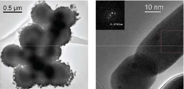
employed [25]. This route can be regarded as a self-combustion synthesis conined within a droplet where urea acts as an in-situ source of thermal energy due to its decomposition. The as-prepared non-agglomerated amorphous powder has broad particle size distribution (200–1400 nm) (Fig. 9). They were additionally ther-mally treated in air at 1000 and 1100°C for 6h pre-serving their morphological characteristics. Despite of precursor modiication during synthesis, performed annealing did not yielded pure YAG:Ce3+ product.
While lower temperature is favourable for YAP and YAM phase segregation, increase of heating tempera-ture enhanced YAG phase formation with YAM phase retention.
Fig.8. SEM/EDS of the YAG:Ce3+ particles obtained through spray pyrolysis of nitrate solution at 900oC and
annealed at 1000oC, 6h (a); TEM of the YAG:Ce3+ particles obtained through spray pyrolysis of nitrate
solution at 320oC and annealed at 1000oC, 6h (b)
crystallized at temperatures as high as 900 and 1000°C gave multiphased powders with different
compositions after 3h of annealing (YAP, YAP, YAM), while prolongation of treatment at higher
temperature result in pure YAG phase formation (Fig.8) [20].
In order to achieve additional heating during YAG:Ce
3+synthesis urea-assisted spray pyrolysis
was employed [25]. This route can be regarded as a self-combustion synthesis confined within a
droplet where urea acts as an
source of thermal energy due to its decomposition. The
as-prepared non-agglomerated amorphous powder has broad particle size distribution (200-1400nm)
(Fig.9). They were additionally thermally treated in air at 1000 and 1100°C for 6h preserving their
morphological characteristics. Despite of precursor modification during synthesis, performed
annealing did not yielded pure YAG:Ce
3+product. While lower temperature is favorable for YAP
and YAM phase segregation, increase of heating temperature enhanced YAG phase formation with
YAM phase retention.
Figure 9. SEM of the as-prepared YAG:Ce3+ particles obtained through urea-assisted spray pyrolysis at
900oC; PL spectra of particles treated at 1100oC(3h).
Figure 8. SEM/EDS of the YAG:Ce3+ particles obtained through spray pyrolysis of nitrate solution at 900°C and annealed at 1000°C, 6 h (a); TEM of the YAG:Ce3+ particles obtained through spray pyrolysis of nitrate solution at 320°C
and annealed at 1000°C, 6 h (b)
143
K. Marinković et al. / Processing and Application of Ceramics 4 [3] (2010) 135–145
Having this in mind, preservation of the molecu-lar homogeneity during precursor synthesis was done through polymerization with an organic complexing agent EDTA and ethylene glycol (EG) [22]. Two reac-tions are involved, a complex formation between EDTA and metals (via four carboxylate and two amine groups) and esteriication between EDTA and EG. Ultrason -ically generated aerosol droplets were decomposed at 600°C in argon atmosphere. Following the initial at-tempt in providing pure YAG:Ce3+ phase generation
the particles were additionally thermally treated for 3 h in air at 1000°C and 1100°C. Comprehensive structur-al anstructur-alysis implied that garnet phase was formed with-out contamination of other phase having different alu-minum yttrium composition even at the lower annealing temperature and in a much shorter time. The spherical dense particles comprised grained-like structure, since they are composed of nanosized garnet monocrystals (Fig. 10). Although uncompleted, cerium incorporation in garnet matrix is conirmed by broad green-yellow emission spectra in the range of 470–670 nm peaking at 521 nm. With this optimization of the spray pyrol-ysis reaction conditions towards synthesis of pure, un-agglomerated YAG:Ce3+ particles with spherical shape
and illed morphology were achieved.
IV. Conclusions
Aerosol route represents a versatile synthesis method for processing novel functional materials. An insight into the diversity of this method and materials that could be produced was briely reviewed. Particularly, it was shown that spray pyrolysis is one of the simplest among them and is capable in ensuring particle spherical morphology, good crystallinity and uniformity in size and shape. Those characteristics are found to be of great value since they re-sult in well deined phosphor powder characteristics es -sential for achieving higher brightness and resolution in
displays. Superior structural, morphological and func-tional properties of Gd2O3:Eu, Y2O3:Eu, (Y1-xGdx):Eu and Y3Al5O12:Ce powders are presented and correlated with the processing parameters applied facilitating further tai-loring of speciic properties in these materials.
Acknowledgement This research is inancially sup -ported through the Project No. 142010 of the Ministry of Science and Technology of the Republic of Serbia and COST 539 Action.
References
H. Tuller, “Solid state electrochemical systems-op-1.
portunities for nanofabricated or nanostructured ma-terials”, J. Electroceram., 1 [3] (1997) 211–218. G.L. Messing, S.-C. Zhang, G.V. Jayanthi, “Ceramic 2.
powder synthesis by spray pyrolysis”, J. Am. Ceram. Soc.,76 [11] (1993) 2707–2726.
L. Madler, “Liquid-fed aerosol reactors for one-step 3.
synthesis of nano-structured particles”, KONA, 22
(2004) 107–119.
R.J. Lang, “Ultrasonic atomization of liquids”,
4. J.
Acoust. Soc. Am.,34 (1962) 6–8.
O. Milosevic, L. Mancic, M.E. Rabanal, L.S. Gomes, 5.
K. Marinkovic, “Aerosol route in processing of nano-structured functional materials”, KONA, 27 (2009) 84–106.
R. Maric, T. Fukui, S. Ohara, H. Yoshida, M. Nishimu-6.
ra, T. Inagaki, K. Miura, “Powder prepared by spray pyrolysis as an electrode material for solid oxide fuel cells”, J. Mater. Sci.,35 (2000) 1–8.
Z.V. Marinkovic, L. Mancic, R. Maric, O. Milosevic, 7.
“Preparation of nanostructured Zn-Cr-O spinel pow-ders by ultrasonic spray pyrolysis”, J. Eur. Ceram.
Soc., 21 (2001) 2051–2055.
K. Okuyama, I.W. Lenggoro, “Preparation of nano-8.
particles via spray route”, Chem. Eng. Sci.,58 (2003) 537–547.
144
K. Marinković et al. / Processing and Application of Ceramics 4 [3] (2010) 135–145
Z.V. Marinkovic, L. Mancic, O. Milosevic, “Nature 9.
of structural changes in nanocrystalline ZnO powders under linear heating conditions”, J. Eur. Ceram. Soc.,
24 (2004) 1929–1933.
V.M. Djinovic, L.T. Mancic, G.A. Bogdanovic, P.J. 10.
Vulic, G. del Rosario, T.J. Sabo, O.B. Milosevic, “Aerosol synthesis of pure and Pt-doped ZnO par-ticles using nitrate and pdda-Pt(IV) complex solu-tions”, J. Mater. Res., 20 [1] (2005) 102–113. S. Grguric-Sipka, T. Sabo, L. Mancic, O. Milosevic, 11.
“Aerosol synthesis of ruthenium doped ZnO ine par-ticles”, J. Aerosol Sci., 35 (2004) S183–184.
Y. Wang, O. Milosevic, L. Gómez, M.E. Rabanal, 12.
J.M. Torralba, B. Yang, P.D. Towsend, “Thermolumi-nescence responses from europium doped gadolinium oxide”, J. Phys. Cond. Matter, 18 (2006) 9257–9272. M.E. Rabanal., L.S. Gómez, A. Khalifa, J.M. Torralba, 13.
L. Mancic, O. Milosevic, “Structural properties of eu-ropia-doped-gadolinia synthesized through aerosol”,
J. Eur. Ceram. Soc.,27 [13-15] (2007) 4325–4328. L.S. Gómez, M.E. Rabanal, J.M. Torralba, L. Mancic, 14.
O. Milosevic, “Structural and morphological study of nanoceramics prepared by spray pyrolysis”, in Char -acterization & Control of interfaces for High Quality Advanced materials - Ceram.Trans., 198 (2007) 193– 197.
K. Marinkovic, L. Mancic, L. Gomez, M.E. Rabanal, 15.
M. Dramicanin, O. Milosevic, “Nanostructured (Y
1-xGdx)2O3:Eu
3+ powders obtained through aerosol
syn-thesis”, ICCCI 2009, Kurashiki, Japan, 2009. K. Marinkovic, L. Mancic, L. Gomez, M.E. Raba-16.
nal, M. Dramicanin, O. Milosevic, “Photolumines-cent properties of nanostructured Y2O3:Eu3+ powders
obtained by aerosol synthesis”, ICOM 2009, Herceg Novi, Montenegro, 2009.
G. del Rosario, S. Ohara, L. Mancic, O. Milosevic, 17.
“Characterization of YAG:Ce powders thermal treat-ed at different temperatures”, Appl. Surf. Sci., 238
[1-4] (2004) 469–474.
O. Milosevic, L. Mancic, S. Ohara, G. Rosario, P. 18.
Vulic, “Aerosol synthesis and phase development in Ce-doped nanophased yttrium-aluminum garnet (Y3Al5O12:Ce) particles”, in Characterisation and Control of Interfaces for High Quality Advanced Ma
-terials- Ceram.Trans.,146 (2004) 435–441.
L. Mancic, G. del Rosario, Z. Marinkovic, O. 19.
Milosevic, “Detailed structural characterization of phosphor YAG:Ce particles obtained via spray pyrol-ysis”, Mater. Sci. Forum,518 (2006) 107–112. L. Mancic, G. del Rosario, Z.V. Marinkovic-Stanoje-20.
vic, O. Milosevic, “Phase evolution in Ce doped yt-trium aluminum based particles derived from aero-sol”, J. Eur. Ceram. Soc., 27 (2007) 4329–4332. Lj. Kandic, K. Marinkovic, L. Mancic, G.del Rosario, 21.
O. Milosevic, “Low temperature aerosol synthesis of YAG:Ce3+ nanostructures: Comparative study of the
XRPD microstructural parameters”, Mater. Sci. Fo -rum,555 (2007) 395–400.
L. Mancic, K. Marinkovic, B. Marinkovic, M. Dram-22.
icanin, O. Milosevic, “YAG:Ce3+ nanostructured
par-ticles obtained via spray pyrolysis of polymeric pre-cursor solution”, J. Eur. Ceram. Soc., 30 (2010) 577–582.
K. Marinkovic, “Structural, morphological and func-23.
tional properties of nanostructured rare-earth oxides obtained through aerosol synthesis”, Master Science Thesis, Belgrade University, 2009.
L.S. Gomez, “Sintesis y caracterization de oxi-24.
dos nanoestructurados de gadolinio e ytrio dopados con europio obtenidos mediante el metodo de spray pirolisis”, Ph.D. Thesis, University Carlos III, Ma-drid, 2009.
K. Marinkovic, L. Mancic, V.B. Pavlovic, M. Dram-25.
icanin, O. Milosevic, “Urea-assisted self-combustion aerosol synthesis of Y3Al5O12:Ce3+”, YUCOMAT,
Her-ceg Novi, Montenegro, 2008.
P.D. Rack, P.H. Holloway, “The structure, device 26.
physics and material properties of thin ilm electrolu-minescent displays”, Mater. Sci. Eng., 4 (1998) 171– 219.
R.C. Ropp,
27. Luminescence and the Solid State,
Elsevi-er Science PublishElsevi-ers B.V., New York, 1991.
M. Maghrabi, P.D. Townsend, G. Vazquez, “Low tem-28.
perature luminescence from the near usrface region of Nd:YAG”, J. Phys.: Condens. Matter, 13 (2001) 2497–2515.
E. Zych, C. Brecher, A.J. Wojtowicz, H. Lingertat, 29.
“Luminescence properties of Ce-activated YAG op-tical ceramic scintillator materials”, J. Lumin., 75
(1997) 193–203.
H. Koo, S. Ju, D.S. Jung, S.K. Hong, D.Y. Kim, Y.C. 30.
Kang, “Morphology control of Gd2O3:Eu phosphor particles with cubic and monoclinic phases prepared by high temperature spray pyrolysis”, Jap. J. Appl. Phys., 45, [6A] (2006) 5018–5022.
J.S. Bae, S.S. Yi, J.H. Kim, K.S. Shim, B.K. Moon, 31.
J.H. Jeong, Y.S. Kim, “Crystalline-phase-dependent red emission behaviours of Gd2O3:Eu3+ thin-ilm
phos-phors”, Appl. Phys. A, 82, [2] (2006) S.369–372. D.J. Seo, Y.C. Kang, S.B. Park, “The synthesis of (Y
32.
1-xGdx)2O3:Eu phosphor particles by lame spray
pyrol-ysis with LiCl lux”, Appl. Phys. A, 77 (2003) 659– 663.
O. Milosevic, R. Maric, S. Ohara, T. Fukui, “Struc-33.
tural and luminescence properties of Gd2O3:Eu3+ and
Y3Al5O12:Ce3+ phosphor particles synthesized via
aerosol”, Ceram. Trans.,112 (2001) 101–106. O. Milosevic, L. Mancic, M.E. Rabanal, B. Yang, P.D. 34.
Townsend, “Structural and luminescence properties of Gd2O3:Eu3+ and Y
3Al5O12:Ce
3+ phosphor particles
synthesized via aerosol”, J. Electrochem. Soc., 152
(2005) G707–713.
S. Jung, Y.C. Kang, J.H. Kim, “Generation of phos-35.
145
K. Marinković et al. / Processing and Application of Ceramics 4 [3] (2010) 135–145
O. Malta, E. Antic-Fidancev, M. Lemaitre-Blaise, A. 36.
Milicic-Tang, M. Taibi, “The crystal ield strength pa -rameter and the maximum splitting of the 7F
1
mani-fold of the Eu3+ ion in oxides”, J. Alloys Compd., 228
(1995) 41–44.
O. Pons, Y. Moll, A. Huignard, E. Antic-Fidancev, P. 37.
Aschehoug, B. Viana, E. Millon, J. Perrière, C. Gara-pon, J. Mugnier, “Eu3+- and Tm3+-doped yttrium
ox-ide thin ilms for optical applications” J. Lumin., 87-89 (2000) 1115–1117.
D.R. Tallant, C.H. Seager, R.L. Simpson, “Energy 38.
transfer and relaxation in europium-activated Y2O3 af-ter excitation by ultraviolet photons”, J Appl. Phys.,
91 (2002) 4053–4064.
Ž. Andrić, M.D. Dramićanin, M. Mitrić, V. Jokanović, 39.
A. Bessiere, B. Viana, “Polymer complex solution synthesis of (YxGd1-x)2O3:Eu3+ nanopowder”, Opt.
Mater., 30 (2008) 1023–1027.
H. Yang, D-K. Lee, Y-S. Kim, “Spectral variations of 40.
nano-sized Y3Al5O12:Ce phosphors via codoping/sub-stitution and their white LED characteristics”, Mater. Chem. Phys.,114 (2009) 665–669.
Y.C. Kang, I.W. Lenggoro, S.B. Park, K. Okuyama, 41.
![Figure 1. Schematic of the hot wall aerosol synthesis route, i.e. spray pyrolysis methodology [5]](https://thumb-eu.123doks.com/thumbv2/123dok_br/18357135.353717/2.892.127.763.110.543/figure-schematic-aerosol-synthesis-route-spray-pyrolysis-methodology.webp)

![Figure 4. HRTEM of Gd 2 O 3 :Eu 3+ particles: primary nano-particles associated with a defect structure (a); cubic phase with Ia3 symmetry taken along the [100] zone with (002) and (020) atomic planes resolved (b); monoclinic phase with c2/m](https://thumb-eu.123doks.com/thumbv2/123dok_br/18357135.353717/4.892.90.809.889.1101/figure-particles-particles-associated-structure-symmetry-resolved-monoclinic.webp)

![Figure 6. Emission spectra of (Y 0.90 Eu 0.10 ) 2 O 3 system (a) and lifetime values of (Y 0.95 Eu 0.05 ) 2 O 3 system under λ ex = 393 nm (λ em = 611 nm) (b) [23]](https://thumb-eu.123doks.com/thumbv2/123dok_br/18357135.353717/6.892.90.807.108.408/figure-emission-spectra-eu-o-lifetime-values-eu.webp)
![Table 2. Main structural characteristics derived trough Rietveld reinement and characteristics of the luminescent measurements for (Y 1-x Gd x ) 2 O 3 :Eu 3+ system annealed at 1100°C [23]](https://thumb-eu.123doks.com/thumbv2/123dok_br/18357135.353717/7.892.92.809.886.1157/structural-characteristics-rietveld-reinement-characteristics-luminescent-measurements-annealed.webp)