http://dx.doi.org/10.1590/S1982-21702015000300036
Artigo
EXPERIMENTAL ASSESSMENT OF TECHNIQUES FOR FISHEYE
CAMERA CALIBRATION
Avaliação experimental de técnicas de calibração de câmaras com objetiva olho
de peixe
José Marcato Junior 1
Marcus Vinícius Antunes de Moraes 2
Antonio Maria Garcia Tommaselli 2
1Faculdade de Engenharias, Arquitetura e Urbanismo e Geografia. UFMS – Universidade Federal de Mato Grosso do Sul. Campus Universitário, 79070-900 Campo Grande, MS. [email protected]
2Faculdade de Ciências e Tecnologia – Departamento de Cartografia. UNESP – Univ Estadual Paulista. Rua Roberto Simonsen, 305, 19060-900 Presidente Prudente, SP. [email protected], [email protected]
Abstract:
Fisheye lens cameras enable to increase the Field of View (FOV), and consequently they have been largely used in several applications like robotics. The use of this type of cameras in close-range Photogrammetry for high accuracy applications, requires rigorous calibration. The main aim of this work is to present the calibration results of a Fuji Finepix S3PRO camera with Samyang 8mm fisheye lens using rigorous mathematical models. Mathematical models based on Perspective, Stereo-graphic, Equi-distant, Orthogonal and Equi-solid-angle projections were implemented and used in the experiments. The fisheye lenses are generally designed following one of the last four models, and Bower-Samyang 8mm lens is based on Stereo-graphic projection. These models were used in combination with symmetric radial, decentering and affinity distortion models. Experiments were performed to verify which set of IOPs (Interior Orientation Parameters) presented better results to describe the camera inner geometry. Collinearity mathematical model, which is based on perspective projection, presented the less accurate results, which was expected because fisheye lenses are not designed following the perspective projection. Stereo-graphic, Equi-distant, Orthogonal and Equi-solid-angle projections presented similar results even considering that Bower-Samyang fisheye lens was built based on Stereo-graphic projection. The experimental results also demonstrated a small correlation between IOPs and EOPs (Exterior Orientation Parameters) for Bower-Samyang lens.
Keywords: Photogrammetry; Camera calibration; Digital cameras; Omnidirectional Systems.
Resumo:
aplicações de alta acurácia na Fotogrametria a curta distância, exige a sua calibração. O objetivo principal é calibrar a câmara Fuji Finepix S3pro com a lente olho de peixe Bower-Samyang 8mm usando modelos matemático rigorosos. Modelos matemáticos baseados nas projeções perspectiva, estereográfica, equidistante, ortogonal e do ângulo equi-sólido foram implementados e usados nos experimentos. As lentes olho de peixe são geralmente fabricadas seguindo um dos quatro últimos modelos, e a lente Bower-Samyang 8 mm é baseada na projeção estereográfica. Os modelos matemáticos foram usados em conjunto com os modelos de distorções radial simétrica, descentrada e de afinidade. Experimentos foram realizados para verificar o conjunto de parâmetros de orientação interior adequado para descrever a geometria interna da câmara. O modelo matemático de colinearidade, baseado na projeção perspectiva, apresentou o resultado menos acurado. As lentes olho de peixe não são fabricadas conforme a projeção perspectiva, o que justifica esse resultado. Os resultados obtidos com as projeções estereográfica, equidistante, ortogonal e do ângulo equi-sólido não apresentam diferenças significativas, embora a lente olho de peixe Bower-Samyang tenha sido construída conforme a projeção estereográfica. Verificou-se também uma baixa correlação entre os parâmetros de orientação interior e exterior para a lente Bower-Samyang.
Palavras-chave:Fotogrametria; Calibração de câmaras; Câmaras digitais; Sistemas omnidirecionais.
1. Introduction
Omnidirectional Vision systems that enable 360° imaging have been widely used in several research fields such as robot navigation, telepresence, close-range Photogrammetry and virtual reality (Kang and Szeliski, 1997; Yagi, 1999; Spacek, 2005; Sturm et al., 2010). Omnidirectional images can be acquired using: camera with fisheye lenses; moving cameras or optical elements; catadioptric systems (camera and mirror); and multiple cameras with divergent views (Sturm et al. 2010). (Van Den Heuvel et al., 2006) presented a system developed by Cyclomedia composed of two fisheye lens camera with a FOV (Field of View) of approximately 185°, generating omnidirectional images called Cycloramas.
The fisheye lens camera should be calibrated to be used in applications that require high accuracy. In Photogrammetry, the Collinearity mathematical model, based on perspective projection combined with lens distortion models, is generally used in the camera calibration process. However, fisheye lenses are designed following different projections models such as: Stereo-graphic, Equi-distant, Orthogonal and Equi-solid-angle. In general, the fisheye lenses follow the Equi-distant and Equi-solid-angle projections (Abraham and Förstner, 2005; Schneider et al., 2009).
(Puig et al., 2012) performed a comparative analysis between some existing generalized (non-physical) mathematical models (Barreto and Araujo, 2002; Scaramuzza et al., 2006; Mei and Rives, 2007; Puig et al., 2011) to calibrate central omnidirectional systems and fisheye lens cameras. It was verified that the calibration methods achieved accurate results in the 3D object reconstruction with GCPs (Ground Control Points) well distributed over the images. (Puig et al., 2011) applied the DLT (Direct Linear Transformation) mathematical model to relate object (3D) and image (2D) spaces in the calibration step.
The main aim of this paper is to present the results achieved in the calibration of a Fuji-Finepix S3pro digital camera with Bower-Samyang 8mm fisheye lens using rigorous mathematical models. The contribution of this work is the assessment of the calibration results of a Bower-Samyang fisheye lens, which is a low cost option in comparison with other fisheye lenses and it is built following the Stereo-graphic projection model (Charles, 2009), which is less commonly used (Ray, 2002). Considering that, experimental assessment on the calibration of Bower-Samyang fisheye lens becomes a relevant issue to enable its use in future projects and in photogrammetric tasks. A correlation analysis between IOPs (Interior Orientation Parameters) and EOPs (Exterior Orientation Parameters) was also conducted.
The mathematical models used in this work are presented in Section 2. Section 3 describes the experiments and results of the fisheye lens camera calibration. Finally, the conclusions are presented in Section 4.
2. Calibration of fisheye cameras
Camera calibration is a procedure to estimate the IOPs, which enable the reconstruction of the perspective bundle that generated the image. The IOPs of digital cameras are the focal length, the principal point coordinates and coefficients for systematic errors correction (lens distortions: symmetric radial and decentering; and affinity). The most used model for camera calibration are the collinearity equations (Schmid, 1959) considering additional parameters – IOPs, as presented in Equation 1. (Mikhail et al., 2001).
where f is the focal length; (XC, YC, ZC) are the 3D point coordinates in the photogrammetric
reference system (Equation 2); (xf, yf) are the image point coordinates in the photogrammetric
reference system; (x’,y’) are the image point coordinates in a reference system parallel to the
photogrammetric system which origin is in the image centre; (x0,y0) are the coordinates of the
where rij (i and j from 1 to 3) are rotation matrix elements that relates the object to the image
reference system; (X, Y, Z) are the coordinates of a point in the object reference system; and (XCP, YCP, ZCP) are the coordinates of the perspective centre (PC) in the object reference system.
where K1, K2, K3 represent symmetric radial distortion coefficients; P1 e P2 are the decentering
distortion coefficients; A and B are the affinity parameters; xf= x’-x0; yf= y’-y0 and;
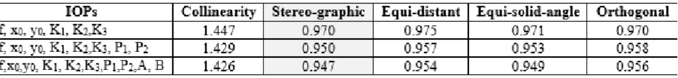
Figure 1: Geometry of the image acquisition with a fisheye lens camera (adapted from Abraham
and Förstner, 2005).
Figure 2: Bower-Samyang 8mm fisheye lens camera (Charles, 2009).
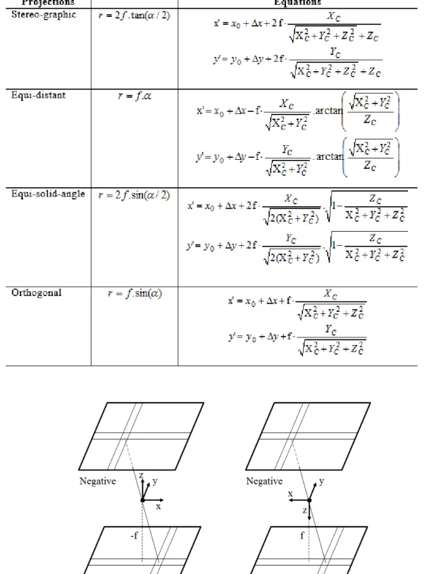
The analysis of Table 1 shows a difference in the focal length sign between the models. In Photogrammetry, generally, the photogrammetric z axis points to the negative plane, and as a consequence, Zc have negative values. This is appliable only in perspective and Equi-distant
projections. In the other projections, this is not possible, because Zc is squared, and Zc2 is a
Table 1: Mathematical models for the calibration of fisheye lens camera (Ray, 2002; Abraham and
Förtner, 2005).
Figure 3: Photogrammetric Systems for the projections: (a) perspective and equi-distant; (b)
3. Experiments and results
The Fuji Finepix S3PRO camera with Bower-Samyang 8mm fisheye lens was calibrated using the Collinearity, Stereo-graphic, Equi-distant, Orthogonal and Equi-solid-angle mathematical models. These mathematical models were implemented in an in-house developed software package called TMS (Triangulation with Multiple Sensors) (Ruy et al., 2009; Marcato Junior and Tommaselli, 2013).
Twelve (12) images collected by Fuji Finepix S3pro with the fisheye lenses, in three exposure stations were used in the calibration process (see Figure 4). In order to automate the calibration process a special 3D terrestrial calibration field with coded targets was created. This 3D field is composed of 139 coded targets, using the ARUCO style (Garrido-Jurado et al., 2014). These targets have two main parts: an external crown, which is a rectangle and 5x5 internal squares that can code 10 bits of information. With this scheme, 1024 values can be encoded. More details about these coded targets are presented in (Tommaselli et al., 2014) and (Silva et al., 2014). A public existing software (Garrido-Jurado et al., 2014) was adapted to perform automatically the location, identification and accurate measurement of the four corners of the external crown of the calibration field targets (Silva et al., 2014). With the adapted software, most of the existing coded targets were automatically located, recognized and the coordinates of the corners of the bounding rectangle are extracted with subpixel precision. To improve the image quality, and consequently to increase the number of corners automatically detected, the shadows were also interactively segmented and enhanced. Some corners that failed to be detected automatically with the software, were interactively measured using MID software (Reiss and Tommaselli, 2003) to provide enough points with suitable geometry for the camera calibration.
Figure 4: Images acquired with Fuji Finepix S3pro camera with Bower-Samyang 8mm fisheye
lens over the 3D calibration field with coded targets.
reference frame, four reference points were surveyed during eight hours with a double frequency GNSS (Global Navigation Satellite System) receiver. To verify the precision of the 3D coordinates of these points, the distances between then were measured with a Total Station and the discrepancies among the electronically measured and those computed from the 3D coordinates were around 1mm. Forty-three (43) images of the calibration field were acquired by a Hasselblad H3D (50 Megapixels) 35 mm lens camera, with a GSD (Ground Sample Distance) of 3 mm. The coordinates of the remaining 552 points were estimated with on the job calibration of the Hasselblad camera, being achieved a precision of approximately 3 mm. These points were considered as photogrammetric points in the on the job calibration. More details of this process are described in (Moraes et al., 2013). This set of 3D coordinates generated by photogrammetric calibration was used as ground control in the following experiments.
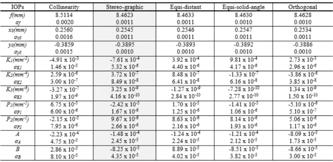
Fuji Finepix S3pro is a 12.1 Megapixel (4256x2848 pixels) digital camera with a pixel size of 5.4 µm. The sensor frame size is 23.0 mm x 15.5 mm. Experiments were conducted with different sets of IOPs. Table 2 presents the standard deviation of unit weight estimated in the bundle adjustment for each mathematical model (a priori value was set as 1). The coordinates of 325 GCPs were introduced in the bundle adjustment as weighted constraints with a standard deviation of 3 mm. An exception occurred to the four GCPs estimated by GNSS surveying, which were weighted considering a standard deviation of 1 mm.
Table 2: Estimated Standard deviation of unit weight ( ).
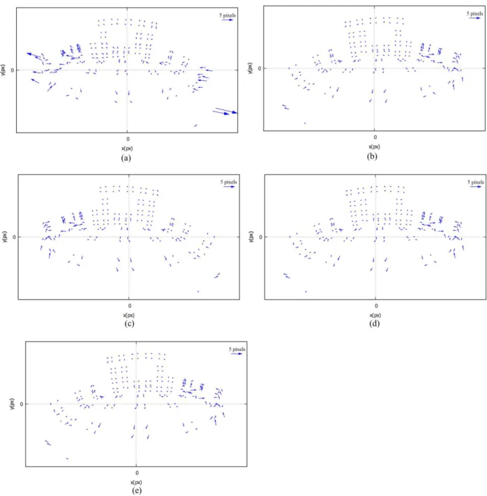
The analysis of Table 2 shows that the standard deviation of unit weight (a posteriori) estimated with the collinearity model is larger when compared to the other models, because the image coordinates residuals are larger (see Figure 5, that shows the residuals distribution for the image 5 of Figure 4, considering all IOPs). The standard deviation of unit weight for the Stereo-graphic, Equi-distant, Equi-solid-angle and Orthogonal are smaller than 1, which is the a priori value. Table 2 also demonstrates that the results for these four models can be considered similar in the light of an analysis considering the standard deviation of unit weight. Table 2 reveals that the best result under this criteria (smaller ) is achieved when all the IOPs (f, x0, y0, K1, K2, K3,
P1, P2, A, B) are considered.
Table 3: Estimated IOPs and standard deviations.
The estimated standard deviation of the IOPs with Stereo-graphic, Equi-distant, Equi-solid-angle and Orthogonal models are smaller when compared to the collinearity model, according to Table 3, which can partially explained by the smaller sigma naught. It is also verified that the standard deviation of the focal length is smaller than 0.4 pixels for all models, showing a precise estimation for this parameter. It is important to mention that the estimated radial distortion parameters (K1, K2, K3) for the collinearity model partially absorbs the effect of the rays’
refraction toward the optical axis, but this modeling is not enough to recover the inner bundle geometry, in comparison with the other models assessed. In the image limits, these values would vanish to infinite, for an angle of incidence of 180º.
Figure 5: Residuals distribution for the studied projections models: (a) Perspective; (b)
Stereographic; (c) Equi-distant; (d) Equi-solid-angle e; (e) Orthogonal.
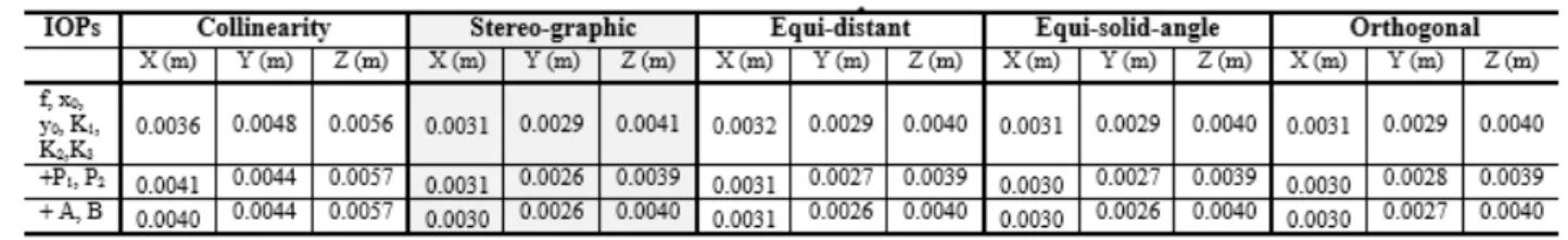
Table 4: RMSE of the checkpoint coordinates.
Table 4 demonstrates that the Stereo-graphic, Equi-distant, Equi-solid-angle and Orthogonal models provided better results in the 3D reconstruction of the checkpoint coordinates in comparison to the collinearity model. The analysis of Table 4 also shows that using the sets of IOPs including the parameters P1, P2, A and B did not improve significantly the 3D
reconstruction.
Finally, a correlation analysis between the IOPs and EOPs was conducted. Table 5 presents the correlation between the focal length and the EOPs, considering the experiment with all IOPs. The results presented in Table 5 revealed that the correlations between focal length and X0,
which is the coordinate representing the depth, are smaller than 0.6. These low correlations value can be explained by the high scale variations caused by the fisheye field of view. The correlations between the other IOPs and EOPs are also small, less than 0.6 in all cases.
4. Conclusion
The aim of this paper was to assess the results of calibration trials performed with a Fuji-Finepix S3pro camera with Samyang 8mm lens, using rigorous mathematical models. Bower-Samyang 8mm, in comparison to the other fisheye lens, is cheaper and is based in a different projection, Stereo-graphic. Charles (2009) points out that Bower-Samyang is neither a fisheye lens nor a perspective projection lens, classifying it as a quasi-stereographic lens.
The mathematical models based on Stereo-graphic, Equi-distant, Orthogonal and Equi-solid-angle projections were implemented in an in-house software called TMS. Experiments were conducted with images from a 3D field calibration with coded targets.
The experiments demonstrated that collinearity mathematical model, which is based on perspective projection, presented the less accurate results, which was expected because Bower-Samyang 8mm lens is not based on perspective projection. Stereo-graphic, Equi-distant, Orthogonal and Equi-solid-angle projections presented similar results in the studied cases, although Bower-Samyang fisheye lens was built based on Stereo-graphic projection. The parameters for systematic errors modelling (lens distortions: symmetric radial and decentering; and affinity) absorbed the radial displacements caused by different fisheye projection models. It was also verified through the experiments a low correlation between IOPs and EOPs, which is justified by the high scale variations caused by a fisheye lens. The experiment aiming the 3D reconstruction showed that Fuji-Finepix S3pro camera with Bower-Samyang 8mm lens, after rigorous calibration with bundle adjustment, can be used for high accuracy applications in close range Photogrammetry.
In future work, techniques will be developed to fully automate the measurement of image points and the calibration process. Experiments will also be performed to compare rigorous and generalized mathematical models to calibrate fisheye lens camera. Line based methods for fisheye calibration is also a topic for further research.
ACKNOWLEDGEMENTS
The authors would like to acknowledge the support of FAPESP (Fundação de Amparo à Pesquisa do Estado de São Paulo) through a PhD Scholarship (p. 2010/16439-3) and CNPq (Conselho Nacional de Desenvolvimento Científico e Tecnológico) through research grants (477738/2009-5, 305111/2010-8 and 456149/2014-7).
REFERÊNCIAS BIBLIOGRÁFICAS
Abraham, S, and Förstner, W. “Fish-eye-stereo calibration and epipolar rectification.” ISPRS Journal of Photogrammetry and Remote Sensing 59 (2005): 278–288. Acessed April 27, 2015.
Barreto, J., and Araújo, H. “Geometric Properties of Central Catadioptric Line Images.” Paper presented at the 7th European Conference on Computer Vision, London, UK, 2002.
Brown, D. C. “Close-Range Camera Calibration.” Photogrammetric Engineering 37 (1971):
855–866.
Conrady, A. “Decentered Lens Systems.”Monthly Notices of the Royal Astronomical Society, 79
(1919): 384–390.
Charles, J. R. “Review of Bower-Samyang 8 mm f/3.5 proportional projection ultra-wide angle lens.” Accessed October 05, 2013. http://www.versacorp.com/vlink/jcreview/sy8rv9jc.pdf. Garrido-Jurado, S., Muñoz-Salinas, R, Madrid-Cuevas, F. J, and Marín-Jiménez, M. J.
“Automatic generation and detection of highly reliable fiducial markers under occlusion.” Pattern Recognition 47 (2014): 2280-2292. Acessed April 27, 2015. doi:
10.1016/j.patcog.2014.01.005.
Hughes, C., Denny, P., Jones, E., and Glavin, M. “Accuracy of fish-eye lens models.” Applied Optics 49 (2010): 3338-3347. Acessed April 27, 2015. doi: 10.1364/AO.49.003338.
Kang, S., and Szeliski. “3-d scene data recovery using omnidirectional multibaseline stereo.” International Journal of Computer Vision, 25 (1997): 167–183.
Marcato Junior, J., and Tommaselli, A. M. G. “Exterior orientation of CBERS-2B imagery using multi-feature control and orbital data.” ISPRS Journal of Photogrammetry and Remote Sensing
79 (2013): 219-225. Acessed April 27, 2015. doi: 10.1016/j.isprsjprs.2013.02.018.
Mei, C., and Rives, P. “Single View Point Omnidirectional Camera Calibration from Planar Grids.” Paper presented at the IEEE International Conference on Robotics and Automation,
Rime, Italy, April, 2007.
Mikhail, E. M., Bethel, J. S., and McGlone, J. C. Introduction to Modern Photogrammetry. New
York: John Wiley & Sons, 2001.
Moraes, M. V. A, Tommaselli, A. M. G., Silva, S. L. A., and Marcato Junior, J. “Implantação de campo terrestre de calibração de câmaras com uso de alvos codificados.” Paper presented at the
VIII Colóquio Brasileiro de Ciências Geodésicas, Curitiba, Brazil, December 1-4, 2013.
Puig, L., Bastanlar, Y., Sturm, P., Guerrero, J. J, and Barreto, J. “Calibration of Central Catadioptric Cameras Using DLT-Like Approach.”International Journal of Computer Vision 93
(2011): 101-114. Acessed April 27, 2015. doi: 10.1007/s11263-010-0411-1.
Puig, L., Bermúdez, J., Sturm, P., and Guerrero, J. J. “Calibration of omnidirectional cameras in practice: A comparison of methods.” Computer Vision and Image Understanding 116 (2012):
120-137. Acessed 27 April, 2015. doi: 10.1016/j.cviu.2011.08.003.
Ray, S. F. Applied Photographic Optics: Lenses and Optical Systems for Photography, Film, Video and Electronic Imaging. Oxford:Focal Press, 2002.
Reiss, M. L. L., and Tommaselli, A. M. G. “Orientação de Imagens sem Pontos de Apoio para Mensuração de Superfícies Planas.”Boletim de Ciências Geodésicas 9 (2003): 121-139.
Ruy, R. S., Tommaselli, A. M. G, Galo, M., Hasegawa, J. K., and Reis, T. T. “Evaluation of bundle block adjustment with additional parameters using images acquired by SAAPI system.”
Paper presented at the 6th International Symposium on Mobile Mapping Technology, Presidente
Scaramuzza, D., Martinelli, A., and Siegwart, R. A. “Flexible Technique for Accurate Omnidirectional Camera Calibration and Structure from Motion.” Paper presented at the IEEE International Conference on Computer Vision System, January 04-07, 2006.
Schmid, H. A. “General Analytical Solution to the Problem of Photogrammetry.” US Ballistic Research Laboratories Report n° 1065, Aberdeen, MD, 1959.
Schneider, D., Schwalbe, E., and Maas, H. –G. “Validation of geometric models for fisheye lenses.”ISPRS Journal of Photogrammetry and Remote Sensing 64 (2009): 259-266. Acessed 27
April, 2015. doi: 10.1016/j.isprsjprs.2009.01.001.
Silva, S. L. A., Tommaselli, A. M. G., and Artero, A. O. “Utilização de alvos codificados do tipo Aruco na automação do processo de calibração de câmaras.”Boletim de Ciências Geodésicas 20
(2014): 636-656. Acessed 27 April, 2015. doi:10.1590/S1982-21702014000300036.
Spacek, L. “A catadioptric sensor with multiple viewpoints.”Robotics and Autonomous Systems
51 (2005):3–15. Acessed 27 April, 2015. doi: 10.1016/j.robot.2004.08.009.
Sturm, P., Ramalingam, S., Tardif, J., Gasparini, S., and Barreto, J. “Camera Models and Fundamental Concepts Used in Geometric Computer Vision.”Computer Graphics and Vision 6
(2010):1–183. Acessed 27 April, 2015. doi: 10.1561/0600000023.
Tommaselli, A. M. G, Marcato Junior, J., Moraes, M.V.A., Silva, S. L. A., and Artero, A. O.
“Calibration of panoramic cameras with coded targets and a 3D calibration field.” Paper presented at the EuroCOW 2014: the Calibration and Orientation Workshop, Castelldefels,
Spain, February 12-14, 2014.
Van den Heuvel, F. A. et al. “Calibration of fisheye camera systems and the reduction of chromatic aberration.” Paper presented at the ISPRS comission V Symposium, Dresden,
Germany, September 25-27, 2006.
Yagi, Y. “Omnidirectional Sensing and Its Applications.” IEICE TRANS. INF. & SIST E82-D
(1999): 568–579. Acessed 27 April, 2015. doi:10.1.1.29.8128.
Willneff, J., and Wenisch, O. “The calibration of wide-angle lens cameras using perspective and non-perspective projections in the context of real-time tracking applications.” Paper presented at the SPIE 8085, Videometrics, Range Imaging, and Applications XI, Munich, Germany, May
25-26, 2011.