Abstract
The cable-suspended bridges differ from the elastic structures be-cause of the inherent nonlinearity of the suspension cables. The primary focus of the available theories is to investigate the effect of nonlinearities associated with the distributed self-weight of the cable and its finite elastic displacements. The main point of depar-ture of this paper is to study the effect of the configurational non-linearity of the weightless linear elastic suspension cables undergo-ing small elastic displacements. Based upon authors’ theory of weightless elasto-flexible planar sagging cables, a new Beam with Elasto-Flexible Support (BEFS) model of the cable-deck interaction is proposed here. Rate-type constitutive equations and third order differential equations of motion are derived for a simple four-node cable-suspended beam structure undergoing small elastic vertical displacements. Static and dynamic analysis of the cable-suspended structures is carried out to reveal their characteristic configuration-al response. The proposed theory is criticconfiguration-ally evconfiguration-aluated in the con-text of existing theories of suspension bridges.
Keywords
Suspension bridges, cable-deck interaction, configurational response, rate-type constitutive equations, third order differential equation of motion, flexural-torsional vibrations.
Mechanics of Cable-Suspended Beams
1 INTRODUCTION
Because of their efficacy in resisting the applied forces, cable-supported bridges are the preferred choice for the construction of long span bridges. Their lightness, slenderness and flexibility renders these structures vulnerable to vibrations and dynamic instabilities when subjected to wind, earth-quake and traffic loads. Assurance of adequate safety and satisfactory performance during their service life requires complex analysis. Cable-suspended bridges differ from the conventional elastic structures in that the cable configuration has also to be determined as part of the cable analysis. Of course, certain details like pylon heights, sag/span ratio of the suspension cables, spacing of hangers, etc. are decided a priori based upon the current design and construction practices (Gimsing and
Pankaj Kumar a Abhijit Ganguli a Gurmail S. Benipal a
a Department of Civil Engineering,
Indian Institute of Technology Delhi, Hauz Khas, New Delhi, India [email protected], [email protected], [email protected]
http://dx.doi.org/10.1590/1679-78253259
Georgakis, 2012). While the deformed configuration under dead loads is thus specified, the unde-formed configuration to achieve this target deunde-formed configuration is still required to be determined (Kim and Lee, 2001). Theoretical prediction of structural behavior of cable-suspended bridges is based upon the assumed cable-deck interaction model which, in turn, is informed by the used theory of the suspension cables.
Extensive survey of the field has revealed that there is a considerable diversity in cable theories dedicated to different applications (Rega, 2004). Still certain aspects of dominant cable theories can be identified. Knowing that the cables lack unique natural passive state, their deformed equilibrium state under self-weight is generally employed to play the role of reference state. The equations of motion are stated in terms of additional dynamic forces and displacements from this reference state (Simpson, 1966; Irvine and Caughey, 1974; Nayfeh and Pai, 2004; Lacabonara, 2013; Greco et al., 2014). Analysis of flexible purely extensible sagging cables is complicated by the physical and geo-metric nonlinearities associated with their nonlinear tension-extension relations and finite elastic deformations (Lacarbonara, 2013). Reduction in cable diameter due to Poisson’s effect (Nayfeh and Pai, 2004) and even exact finite deformation kinematics a la continuum mechanics (Luongo et al., 1984) are incorporated. Many a time, it is sufficient to use the linearized theory, e.g., while conduct-ing, the modal analysis of the structure undergoing small displacements from the reference state (Irvine and Caughey, 1974).
Kinematical description is based upon the position vector as a function of the Lagrangian coor-dinate along the cable length and the assumed constitutive equation relates the local axial tension with the local stretch (Luongo et al., 1984, Antman, 2005; Lacarbonara, 2013). In the incremental or updated Lagrangian formulations, there exists a diversity of approaches for establishing the tan-gent stiffness of the cable. Generally, it is determined as the sum of tantan-gent elastic and geometric stiffness matrices, the latter being defined as related to the change in components of the tensile force in the initial reference state (Lacarbonara, 2013). In the finite element formulations, the dis-tributed self-weight of the cable is another source of nonlinearity in the nodal force-displacement relations. In this case, the relevant geometric stiffness matrix is estimated by using the stability functions from the theory of elastic beam-columns (Thai and Kim, 2008). In contrast, some re-searchers have preferred to obtain the tangent stiffness matrix by inverting the tangent flexibility matrix (Santos and Paulo, 2011; Coarita and Flores, 2015).
used to simulate the cable deck interaction. Flexural-torsional deck vibrations are found to be cou-pled with vibrations of the suspension cables (Lepidi and Gattulli, 2014). In the cable-deck interac-tion models, the deformed configurainterac-tion of the cable-suspended bridges under dead loads is general-ly employed as their reference configuration (Niazy et al, 1991; Lacarbonara, 2013; Lepidi and Gat-tulli, 2014). Tangent stiffness matrices are generally employed for carrying out the incremental analysis of suspension bridges (Altin et al., 2012; Lacarbonara, 2013). An elastic catenary element method for form finding and static analysis of cable structures with taut as well as slack cables is also proposed (Greco et al., 2014).
The elastic deformations and the resulting inclination of the hangers do not have much effect on the structural behavior of the cable-suspended structures (Abdel- Ghaffar, 1976). Free vertical and torsional vibrations have been found to be coupled. It has been found that the seismic vibration amplitudes of the cable-supported bridges in the lowest vibration modes of the cables and the tor-sional modes of the deck are negligible. Coupled flexural, tortor-sional and lateral vibration response of suspension bridges is recently simulated by using exact spatial models of the suspension cables and the complete structure. Under the action of harmonic loading, suspension bridges are predicted to exhibit subharmonic resonance, multiple stable and unstable responses, etc. Aero-elastic phenomena like flutter and torsional divergences are also predicted under wind loading (Lacarbonara, 2013).
Recently, the authors have proposed a theory for the static and dynamic analysis of single weightless planar cables with point masses. Their approach is informed by the appreciation that weightless cables lack unique passive state configuration. Such cables are shown to exhibit charac-teristic configurational nonlinearity distinct from the conventional material and geometrical nonlin-earities. The proposed theory involves rate-type constitutive equations and third order equations of motion. Pure and mixed configurational and elastic modes of vibration are predicted (Kumar et al., 2016a). These configurational and elastic vibration modes are shown to be predominantly associated with horizontal and vertical seismic excitations respectively (Kumar et al., 2015).
In this paper, the mechanical foundations of the static and dynamic response of the cable-suspended bridges are explored. A canonical problem of a single span bridge deck cable-suspended from two weightless elasto-flexible planar cables by four vertical rigid hangers is formulated. The initial configuration of the cable-suspended structure undeformed in its passive state is specified. Using the authors’ theory of weightless cables, a Beam with Elasto-Flexible Support (BEFS) model is pro-posed for simulating the cable-deck interaction. Assuming small elastic displacements of the deck and the cable, rate-type constitutive equations and third order equations of motion are derived. The typical elasto-configurational nature of static and dynamic response of the cable-suspended struc-tures is predicted. The approach followed and structural response predicted by the proposed theory of cable-suspended structures are discussed.
2 BEAM WITH ELASTO-FLEXIBLE SUPPORT (BEFS) MODEL
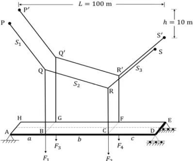
A rather simple suspension bridge consist of simply supported weightless deck ADEH suspended
from two identical elasto-flexible cables PQRS and P Q R S at four nodal points B, C, G, and F
(Fig-ure 1) is considered. For the convenience of stating the relevant equations in the matrix form, the
nodal points B, C, G, and F on the deck are also identified as nodes 1, 2, 3 and 4 respectively. The
deck can be considered as a beam with elasto-flexible support. In its passive state, the deck,
weight-less vertical rigid hangers (QB, RC, Q G and R F) and weightless planar cables are stress-free and
undeformed.
Figure 1: Geometrical details of cable-suspended structure.
Under the action of vertical downward nodal forces , , , , the linear elastic deck
under-goes small vertical displacements , , , . The hangers carry a part of the applied loads as
tensile forces , , , . The remaining part , , , of the applied loads is resisted
by the deck and transferred to the supports. The point masses are located at the nodes 1, 2, 3 and 4 only. Obviously, each cable is under the action of two vertically downward forces applied through the vertical hangers.
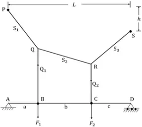
The response of one of these cables PQRS in the BEFS model as shown in Figure 2, is described
here. This description is based upon Authors’ theory of weightless sagging planar cables (Kumar et al., 2016a). In its passive state, the cable configuration is defined by the coordinates of cable nodes
Q , and R , assuming cable as inextensible. Upon loading, the cable is assumed to
un-dergo small nodal elastic displacements , and , respectively in reference to its
equilib-rium configuration of inextensible cable. The nodal coordinates are unique functions of the
nod-al force while the converse is not true. The following rate-type constitutive equations apply:
(1)
nod-al coordinates , of suspension cables , its small elastic displacements , coefficients and of compliance matrices are functions homogeneous of order zero, 1, -1 and zero of force and respectively.
Figure 2: BEFS model.
To recapitulate, in its passive state, the cable-suspended structure is stress-free and undeformed.
The cable configuration in this state is defined by its nodal coordinates . Upon application of
nodal loads ( , ) on the deck, both the cable and the deck undergo vertical elastic displacements.
Additionally, the cable configuration changes as evidenced by changes in its nodal coordinates .
Thus, the cable undergoes horizontal as well as vertical configurational and elastic displacements. However, here only its vertical nodal displacements in the direction of vertical nodal loads are being considered. The compatibility condition relating the nodal displacements of the cable and the deck is stated as
(2)
Here, represents the nodal elastic displacements of the deck. The total displacements of the
cable node, Q and R, of the hangers are composed of two components, viz., the configurational
dis-placements ( ) from the natural state of the cable and the elastic displacements from
its instantaneous natural state . Using Eq. 1 and 2, the constitutive equation at the cable nodes
takes the form as
(3)
Here, represents the tangent elasto-flexible stiffness matrix of the cables. The above
cables in the total structure are identical but uncoupled. To be specific, the coefficients of the
ma-trix representing the coupling between the nodes Q and R of one cable and nodes Q and R of the
second cable vanish.
The deck assumed as linear elastic, its stiffness matrix plays the role of both the
se-cant and tangent stiffness matrices. As a matter of fact, the flexibility matrix of the beam is
determined by applying the classical theory of linear elastic structures. From skeleton structure shown in Figure 3, the deck slab is modelled as a beam with flexural and torsional rigidity values
and respectively. Under the action of nodal forces , , , each applied at eccentricity
equal to half the deck width, the deck undergoes flexural and torsional nodal displacements.
Figure 3: Modelling of Cable-suspended structures.
At both the ends of the beam, the supports are capable of mobilizing torque, but not any flex-ural moment. The constitutive equations relating the nodal loading and their time rates with nodal displacements and their time rates are stated as:
(4)
From dynamic equilibrium equation for the damped structure derived from Newton’s law of motion stated below, yields the value of the hanger forces:
(5)
Here, represent the applied nodal forces with constant force component and harmonic
component . This equation of motion cannot be stated in the familiar form as , but only
matrix is considered to be determined by only the initial stiffness matrix of the structure and the nodal mass matrix as
(6)
Thus, using the constitutive equations the following third order differential equation of motion can be stated for the damped cable-suspended deck:
(7)
For specified initial nodal displacements ̅ and velocities , the nodal initial
acceler-ations are expressed below. Here, initial forces correspond to the initial nodal displacements ̅.
(8)
At any instant the condition of dynamic equilibrium (Eq. 5.7) is satisfied. The hanger forces yield and satisfy the compatibility condition as
(9)
3 STATIC ANALYSIS
Static analysis involves the determination of the structural response to applied nodal loads. The analysis cannot be started from the natural state because, in the absence of the hanger forces, the tangent configurational and elastic compliance matrices of the suspension cables cannot be defined. However, the internal forces as well as the nodal elastic displacements introduced by dead loads are already known. Thus, the changes in the internal forces and nodal displacements introduced by
additional nodal loads – are to be determined. As per the proposed BEFS Model, only
rate-type constitutive equations are valid. For conducting quasi-static analysis of this cable-suspended structure, these rate-type constitutive equations are restated in the following incremental form as:
(10)
One set of such nodal forces ; ; ; kN is identified here as being
caused by dead load. The other structural details are as follows:
Deck: m, m, m, m,
. x N/m , . m , . x N/m , . m
Cables: . m, . m, . m, m,
. m , x N/m
well as the internal forces ( and ) are determined corresponding to a particular set of dead load nodal forces . Here, the nodal loads caused by the dead load of the structure corresponding to its specified cable configuration are determined. The converse problem, faced by the bridge design-ers, the requirements of establishing the configuration of the suspension cables for known dead loads acting at specified locations on the deck is not addressed in this paper.
It should be appreciated that these incremental constitutive equations are valid only for
infini-tesimally small nodal load increments, but not for the finite load increments ∆ . Such happens to
be the case because the instantaneous tangent stiffness matrix and so , is to be updated after application of each load increment. In view of this fact, the following method of static analysis is
proposed: Consider that the additional nodal loads ∆ are applied in small load increments .
Determine , and . Then, determine and
. Update the magnitudes of , , , and . Using and , determine , , , and .
These tangent stiffness matrices and are valid for the next small load increment .
Proceed-ing in this manner, the structural response for any applied load set can be determined.
Here, only the nodal vertical coordinates defining the cable configuration and the vertical
elastic displacements of the cables and the deck are presented. Under the above specified
dead loads and given structural parameters, the following equilibrium configuration and displace-ments are obtained:
. ; . ; . ; . m
. ; . ; . ; . m
The structural response is determined in the form of some equilibrium state of the structure.
The cable configuration and the elastic displacements and ) correspond to the
equilibri-um sustained nodal forces . The predicted dynamic response is presented in terms of
configura-tional displacements of the cable , elastic displacements of the cable and
the elastic displacements of the deck from this equilibrium state. Figure 4(a) shows
the structural response when a specific set of nodal loads is applied along the proportional load path on the structure in its passive natural state. The configurational displacements experienced by the cable imply non-proportional variation of the hanger forces.
Figure 4: Node 1 response (a) general proportional loading and (b) proportional loading. (b)
The consequent nonlinearity in the cable response is reflected in the nonlinear increase of its elastic response as well as of the total displacement at the same node with general proportional increase in applied loading. It has been verified through not presented here that, if the dead load is proportionately increased, no change in cable configuration occurs and the elastic displacements of the cable and the deck increases in a linear manner. Figure 4(b) represents the structural response to a particular case of non-proportional loading achieved by increasing equally nodal loads at nodes 1 and 3 keeping the other nodal loads constant. As observed by others as well (Lacarbonara, 2013), the nonlinear variation of deck displacement at node 1 implies hardening of the structure with in-crease in loads, while dein-crease of loads causes its softening. In all these cases, the configurational
displacements of the suspension cables are of the same order as the elastic displacements.
4 DYNAMIC ANALYSIS
The dynamic response of the structure is determined using third order differential equation of mo-tion expressed in Eq. 7. Runge-Kutta method is applied for solving third order differential equamo-tion of motion. Newmark-Beta method with constant rate of acceleration is also used in validation of Runge-Kutta method. Nodal response at the end of small discrete time interval is obtained. The tangential stiffnessmatrix is assumed to remain constant during this small time-step. The stiffness and damping matrices corresponding to the nodal forces required to introduce the specified initial
displacement are relevant for the first time-step. Here, the cables are assumed to always be in
tension. For the theoretical prediction presented in this paper, such has been verified to be the case.
The damping ratio for the lowest two modes is considered as 0.05 for obtaining the damping
matrix.
The dynamic response predicted at the end of each time-step includes nodal velocity ,
accel-eration and triacceleration . The nodal velocities and the acceleration so predicated are
re-lated to magnitudes of the hanger forces acting on the cables as per Eq. 5 of dynamic
equilibri-um. The configurational and the elastic displacements , of the cables pertain to the upper ends
of the hangers. Then, there is a compatibility from Eq. 2 has also to be satisfied. The two
un-knowns, and can be obtained by solving these two nonlinear simultaneous equations. However,
this approach is not followed here. Instead, using the Runge-Kutta method, nodal displacements
at the end of time step are directly calculated from solving third order equation of motion.
Then, the hanger forces is determined using Eq. 5 which yields the configuration and elastic
displacements of the cables. The tangent configurational and elastic flexibility matrices then
determined and so the stiffness matrix is calculated at the end of each time step required for the next time step. Here, the compatibility equations relating , and are not explicitly used, but it is verified for many cases that the compatibility conditions are indeed satisfied.
Under the dead load, the linear natural frequencies and the mode shapes corresponding to the antisymmetric flexural (ASF), symmetric flexural (SF), antisymmetric torsional (AST) and sym-metric torsional (ST) modes respectively are presented in Table 1.
In the present case, linear modal analysis pertains to small amplitude vibrations of the corre-sponding undamped structure about its equilibrium state under dead loads. The equation of motion,
Eq. 7 can be recast as an eigenvalue problem as . Here, the eigenvalues of the matrix
corre-sponding eigenvectors in the form of modal velocity vectors represent the respective mode shapes. In view of Eq. 7, these modal velocity vectors correspond to the respective modal rates of loading. When the structure under dead loads is perturbed by any of these modal velocity vectors, it exe-cutes ‘free’ vibrations about the equilibrium state at the corresponding linear natural modal fre-quency.
Modes Angular frequency (rad/s) Mode shape (Eigenvectors) ASF 3.5290 (-0.4964; 0.5036; -0.4964; 0.5036)
SF 6.0402 (0.5355; 0.4618; 0.5355; 0.4618)
AST 6.8642 (0.1766; -0.6847; -0.1766; 0.6847)
ST 7.3666 (0.6898; 0.1556; -0.6898; -0.1556)
Table 1: Modes of vibration.
The structure can be set into such modal vibrations by perturbing it by initial displacement vector proportional to the modal velocity vectors. The structure can be forces into modal vibrations
by subjecting it to harmonic loading with peak sinusoidal force vector proportional to the
cho-sen modal velocity vector. It needs to be understood that, in the symmetric flexural and torsional modes, the cables experience purely elastic displacements, while in the anti- symmetric flexural and torsional modes are characterized by purely configurational displacements. The natural frequencies of the deck alone for the anti-symmetric flexural and torsional modes (3.36 rad/s and 6.86 rad/s)
can be observed to be approximately equal to those of the cable supported structure. In
contrast, the absence of the cable results in considerable decrease in the symmetric flexural and torsional frequencies (0.96 rad/s and 4.35 rad/s) of the structure.
Obviously, the cables contribute to the elastic resistance of the structure only in the symmetric modes of deformation and vibration. When the structure deforms or vibrates in the anti- symmetric modes, the contribution of the cables to the elastic resistance of the cable-suspended structure is minimal. Further, it has been estimated that about 96% of the dead load is resisted by the cables. It must be realized that the structural response of the cable-suspended structure under dead load corresponds to its symmetric flexural mode. Thus, in this purely elastic mode, the contribution of the cables to the elastic stiffness matrix of the cable-suspended structure is many times than that of the deck. Still, cables do not have much effect on the anti- symmetric configurational modes of the structure.
Typical steady state forced wave-forms for the anti-symmetric and symmetric flexural modes are presented respectively in Figure 5(a) and Figure 5(b). The anti- symmetric flexural response at node 1 can be observed to be mainly configurational with little elastic response of the cable. In con-trast, the symmetric flexural response at the same node is mainly associated with elastic displace-ments of the cable and with little change in cable configuration. Even though the peak amplitude in the anti-symmetric flexural mode is higher, the cable experiences smaller tensile forces in this case
Figure 5: (a) Anti- symmetric modal response, (b) symmetric flexural modal response, and (c) modal tensile forces.
Frequency domain response (FDR) under certain general sinusoidal loading as depicted in Fig-ure 6(a) exhibits a peculiar phenomenon. The node 3 does not register peak response corresponding to anti- symmetric response at forcing frequency of 6.89 rad/s. This phenomenon can be explained by comparing the response waveforms for nodes 3 and 4 as depicted in Figure 6(b) and Figure 6(c) respectively at the same frequency. The configurational and elastic vibration amplitudes of the cable can be observed to be out of phase at node 3 while they are in phase at node 4. Because of the low-er predicted displacements of the deck at the formlow-er node, no resonance peak is obslow-erved. As the predicted response at the latter node is higher, a resonance peak is observed. Similar explanation holds for the absence of the resonance peak for node 4 at frequency of 7.7 rad/s.
(a) Typical FDR
(b) Response components of cable node 3 (c) Response components of cable node 4
Figure 6: (a) Typical FDR of and nodal waveforms at forcing frequency 6.89 rad/s.
(a) (b) (c)
(b) (c)
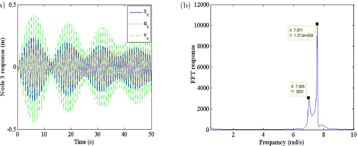
In another case of loading ( ; ; ; kN), the highest two linear modal fre-quencies (ASF: 3.6680, SF: 6.0231, ST: 7.0386, AST: 7.5322) rad/s turned out to be almost equal. Under harmonic loading ( : [227.8; -659.2; 195.1; 689.8]) kN corresponding to the anti- symmetric torsion (AST) mode but at the symmetric torsion linear modal frequency, this structure with much lesser damping is predicted to exhibit transient beating phenomenon. Like the elastic displacements of the deck, the elastic and configurational displacements are also observed from Figure 7(a) to exhibit similar beating phenomenon. Fast Fourier Transform (FFT) plot depicted in Figure 7(b), the beat frequency (0.5 rad/s) equals the difference between the adjacent linear modal frequencies. The harmonic response frequency gradually varies from the lower to the higher of the adjacent fre-quencies as confirmed by the corresponding peaks appearing in the FFT plot.
Figure 7: (a) Typical beating phenomenon and (b) FFT plot of cable node 3.
Inextensible cables can be modelled as elastic cables with very high axial elastic stiffness. Such an inextensible cable-suspended structure will have different configuration under the same dead loads. Its modal frequencies of a particular structure under dead loads are obtained as (3.55, 7.11, 187.71, 187.75) rad/s. The largest two frequencies in fact correspond approximately to the ‘expected infinitely high frequencies’ for the symmetric flexural and torsional modes of structure with inexten-sible cables. It has been verified that the lowest two frequencies indeed pertain to the anti- symmet-ric flexural and torsional modes. The frequency domain response of such a structure subjected to a particular harmonic loading shown in Figure 8(a) exhibits resonance peaks corresponding to these anti- symmetric flexural and torsional modes. The waveform depicted in Figure 8(b) confirms the expectation that the structural response is purely configurational with the elastic response being vanishingly small.
Figure 8: (a) Typical FDR and (b) response components for cable node 1 (at 3.54 rad/s) for general loading.
5 DISCUSSION
In this paper, a new theory of cable-suspended structures with weightless cables and linear elastic deck both undergoing small elastic displacements is proposed. Also, the cables are assumed to be linear elastic in tension. Thus, the usually investigated sources of nonlinearity, viz., the effect of self-weight, physical nonlinearity and finite elastic displacements of the cable on its stiffness, are absent in the present case. The nonlinearity of such cable-suspended structures is caused only by the de-pendence of natural state of the suspension cables upon the applied nodal loads. Changes in the configurational-defining coordinates of the cable nodes with non-proportional variations in applied loads are called configurational displacements. Based upon authors’ theory of weightless sagging planar cables, a new Beam with Elasto-Flexible Support (BEFS) model is proposed for simulating the cable-deck interaction. Its main point of departure is the distinction between the elastic and configurational components of the suspension cable response (Kumar et al., 2016a).
As discussed in Authors’ earlier paper, the weightless elastic cables lack unique passive state but their equilibrium state under specified loads is unique. Also, for each equilibrium state, there corresponds a unique natural state attained by proportional unloading. Also, this natural state is
identical with the equilibrium state of the corresponding inextensible cable. The nodal elastic
displacements are measured relative to this natural state (Kumar et al., 2016a). In contrast to
single sagging cables, the cable-suspended structures possess a unique natural passive state. It is this natural state which plays the role of reference state for defining the configurational displacements of the cables and the elastic displacements of the deck, while the elastic displacements of the suspen-sion cables are measured form their respective natural states under the hanger forces.
Modal response to smaller sinusoidal forces relative to sustained forces is predicted to be linear. Such linearity is confirmed here by the independence of the resonance frequencies of the magnitudes of the sinusoidal forces and by the proportionality between the resonance peak amplitudes with these peak sinusoidal forces. However, these structures exhibits their nonlinearity in the form of dependence of its linear natural frequencies on the sustained loads. Even the crossover phenomenon investigated earlier for sagging cables (Irvine and Caughey, 1974) is predicted here as well for the cable-suspended structures. Beating phenomenon is also predicted at forcing frequencies closer to adjacent natural frequencies.
Even though the configurational displacements of the cables are quite small, they are of the same order as the elastic displacements of the cables and the deck. It has also been shown that, in the antisymmetric flexural and torsional modes, the configurational response dominates the elastic response of the suspension cables. In some cases, or even at some nodes, these configurational and elastic amplitudes happen to be out of phase resulting in smaller deck response. To cite an extreme example, the configurational displacement (-0.3997 m) and elastic displacement (0.3997 m) of the cable at point Q are of opposite sense and so the elastic displacement of the deck at node 2 becomes zero. It has also been demonstrated that higher nodal amplitudes of the deck do not always imply higher tensile forces in the suspension cables. Structures with inextensible suspension cables are predicted to exhibit only configurational vibrations in the antisymmetric flexural and torsional modes. Irrespective of their axial elastic stiffness, the suspension cables are observed not to affect the natural frequencies in these antisymmetric modal vibrations of the cable-suspended structures.
The methods intended for incorporating the effect of large displacements of cable-suspended bridges on their behavior are oblivious of the distinction between the configurational nonlinearity and the conventional geometric nonlinearity associated with the large elastic displacements. In fact, the cables under only one vertical load chosen in one case for illustrating the concept of tangent stiffness matrix is incapable of exhibiting the configurational displacements under (only proportion-al) load increments (Altin, et al., 2012). Of course, the kinematic description of the deformed state of the cable in terms of position vector as a function of the Lagrangian coordinate (Luongo, et al., 1984; Antman, 2005; Locarbonara, 2013; Greco et al., 2014) includes, perhaps unknowingly so, the configurational response in addition to the effect of finite elastic displacements.
To recapitulate, following authors’ approach for the single sagging cables, rate-type constitutive equations and third order differential equations of motion are derived for the cable-suspended struc-ture. Thus, an initial value problem distinct from the conventional initial value problem involving second order differential equation of motion has been formulated. In place of a single set of conven-tional coupled second order differential equations of motion, the governing equations for the cable-suspended structure is involve three sets of coupled equations: coupled third order differential equa-tions of motion, the equaequa-tions of dynamic equilibrium and the compatibility equaequa-tions. Also, apart from the well-known initial nodal displacements and velocities, the third order equations of motion require the specification of the initial nodal accelerations. It is argued here that the required initial nodal accelerations are determined by specified initial nodal displacements and velocities as per Eq. 10. A simple canonical cable-suspended structure is selected for illustrating the main concepts and predictions of the proposed theory.
an extended theory is equivalent with the existing theories. Such an exercise is expected to lead to a better theory of cable-suspended structures. Only then will it make any sense to undertake its em-pirical validation and explore possible applications.
6 CONCLUSIONS
It has earlier been established by the authors that the static and dynamic response of the elasto-flexible sagging planar cables is composed of configurational and elastic components. Following the same approach, a new BEFS model involving rate-type constitutive equations and third order dif-ferential equations of motion for cable-suspended structures undergoing small elastic displacements is proposed in this paper. Static and dynamic analysis reveals considerable role played by the con-figurational response of the planar cables. Structural response to small additional loads is approxi-mately linear, but linear modal frequencies are determined by sustained loads. In particular, the vibration response in the antisymmetric flexural and torsional modes is mainly contributed by the configurational response of the cables. Cable configuration is predicted to remain substantially in-variable in the symmetric modes. When the configurational and elastic components of cable re-sponse happen to be out of phase, lesser vibration amplitudes of the deck are predicted but tensile forces in the suspension cables can still be higher. Structure with inextensible cables is found to exhibit only configurational response. The initial value problem posed and solved here for cable-suspended structures is distinct from the conventional formulations. Only further comparative anal-ysis will establish the appropriateness of the proposed theory vis-a-vis the extant theories.
Acknowledgement
The authors express their sincere thanks towards the Indian Institute of Technology Delhi, New Delhi, India for providing research facility for this work.
References
Abdel- Ghaffar A.M and Rubin LI. (1983a). Nonlinear free coupled vibrations of suspension bridges: Theory. Journal of Engineering Mechanics. ASCE 1983b; 109: 319-329.
Abdel- Ghaffar A.M. (1976). Dynamic analysis of suspension bridge structures, Ph.D. Thesis California Institute of Technology Pasadena California 1976.
Abdel- Ghaffar A.M. and Rubin, L.I. (1983b). Nonlinear free coupled vibrations of suspension bridges: Application. Journal of Engineering Mechanics. ASCE 1983a; 109: 330-345.
Altin, S., Kaptan K. and Tezcan S.S. (2012). Dynamic analysis of suspension bridges and full scale testing. Open Journal of Civil Engg. 2012; 2: 58-67.
Antman, S.S. (2005). Nonlinear Problems of Elasticity, Springer.
Coarita, E. and Flores, L. (2015). Nonlinear analysis of structures cable–truss. IACSIT Int. J. of Eng. Tech. 7(3): 160-169.
Gazzola, F., Jleli, M. and Samet, B. (2014). On the Melan equation for suspension bridges. Journal of Fixed Point Theory and Applications, 16(1-2), pp.159-188.
Greco, L., Impollonia, N. and Cuomo, M.A. (2014). Procedure for the static analysis of cable structures following elastic catenary theory, HAL Archieves-ouvertes.
Irvine, H.M. and Caughey, T.K. (1974). The linear theory of free vibrations of a suspended cable. Mathematical and Physical Sciences 341(1626): 299-315.
Kim, K.S. and Lee, H.S. (2001). Analysis of target configurations under dead loads for cable-supported bridges. Computers and Structures 79: 2681-2692.
Kumar, P., Ganguli, A. and Benipal, G.S. (2015). Seismic analysis of weightless sagging elasto-flexible cables. Proc., Structural Engineering Convention (SEC), Dec, 22-24, 2014, IIT Delhi and Advances in Structural Engineering, Springer 1543-1562.
Kumar, P., Ganguli, A. and Benipal, G.S. (2016a). Theory of weightless sagging elasto-flexible cables. Latin Am. J. Solids Struct. (13): 155-174.
Lacarbonara, W. (2013). Nonlinear Structural Mechanics: Theory Dynamical Phenomenon and Modelling, Springer. Lepidi, M. and Gattulli, V.A. (2014). Parametric multi-body section model for modal interactions of cable-supported bridges. J. Sound Vib. 333: 4579-4596.
Luongo, A., Rega, G. and Vestroni, F. (1984). Planer non-linear free vibrations of an elastic cable. Int. J. Non-Linear Mech. 19: 39-52.
Nayfeh, A.H. and Pai, P.F. (2004). Linear and Nonlinear Structural Mechanics. Wiley Interscience.
Niazy, A.S.M., Abdel-Ghaffer, A.M. and Masri, S.F. (1987). Performance of the Vincent-Thomas Suspension on Bridge during the Whittier, California Earthquake of October 1, 1987. Report No. CRECE 91-05. Department of Civil Engineering. University of Southern California, Los Angeles, California. USA 1991.
Rega, G. (2004). Nonlinear vibrations of suspended cables-Part I: Modelling and analysis. Appl. Mech. Rev. 57(6): 443-478.
Santos, H.A.F.A. and Paulo, C.I.A. (2011). On a pure complementary energy principle and a force-based finite ele-ment formulation for non-linear elastic cable. Int. J. of Non-Linear Mech. 46: 395-406.
Simpson, A. (1966). Determinations of inplane natural frequencies of multispan transmission lines by a transfer ma-trix method, Proc. Inst. Electr. Eng. 113: 870-878.
Thai, H.T. and Kim, S.E. (2008). Second-order inelastic dynamic analysis of three-dimensional cable-stayed bridges. Steel Str. 8: 205-214.