Electrical properties of the electroceramic composite in the microwave frequency range:
Pb(Fe0.5Nb0.5)O3 (PFN)–Cr0.75Fe1.25O3 (CRFO)
This article has been downloaded from IOPscience. Please scroll down to see the full text article.
2008 Phys. Scr. 78 065704
(http://iopscience.iop.org/1402-4896/78/6/065704)
Download details:
IP Address: 200.19.190.159
The article was downloaded on 19/04/2012 at 19:46
Please note that terms and conditions apply.
Phys. Scr.78(2008) 065704 (6pp) doi:10.1088/0031-8949/78/06/065704
Electrical properties of the
electroceramic composite in the
microwave frequency range:
Pb(Fe
0
.
5
Nb
0
.
5
)O
3
(PFN)–Cr
0
.
75
Fe
1
.
25
O
3
(CRFO)
M R P Santos
1, F N A Freire
1,2,3, R S T M Sohn
1, J S Almeida
1,
E O Sancho
1,4, A D S B Costa
1,4, A M L Medeiros
1,4and A S B Sombra
11 Laboratório de Telecomunicações e Ciência e Engenharia dos Materiais (LOCEM),
Departamento de Física, Universidade Federal do Ceará, Caixa Postal 6030, CEP 60455-760, Fortaleza, Ceará, Brazil
2Departamento de Química Orgânica e Inorgânica, Universidade Federal do Ceará, CEP 60455-760,
Fortaleza, Ceará, Brazil
3Faculdade de Educação, Ciências e Letras do Sertão Central—Curso de Química/Universidade
Estadual do Ceará—CEP 63900-000, Quixadá, Ceará, Brazil
4Departamento de Engenharia de Teleinformática, Universidade Federal do Ceará,
CEP 60455-970, Fortaleza, Ceará, Brazil
E-mail:[email protected]
Received 26 March 2008
Accepted for publication 25 September 2008 Published 19 November 2008
Online atstacks.iop.org/PhysScr/78/065704
Abstract
In this paper, a new electroceramic composite [Pb(Fe0.5Nb0.5)O3 (PFN)]Z[Cr0.75Fe1.25O3 (CRFO)]100−Z(Z=0,10)is investigated in the microwave (MW) frequency range. The dielectric permittivity and loss in the region of 4–8 GHz (G and H MW bands) were studied. The performance of cylindrical resonator antennas based on CRFO100 and on PFN10 was examined. The experimental and theoretical results of the dielectric resonator antenna (DRA) such as return loss, bandwidth, input impedance and radiation patterns are in good agreement for both composites: PFN10 (10% PFN + 90% CRFO) and CRFO100 (100% CRFO). A numerical validation was made considering an air gap between the dielectric resonator and the metallic conductors. The PFN10 matrix composite PFN10 (10% PFN + 90% CRFO) presents the highest dielectric permittivity (9.9 at 4.44 GHz) and the lowest bandwidth (9.9%). The CRFO100 phase (100% CRFO) presents a dielectric permittivity of 8.35 at 4.67 GHz and a bandwidth of 11.8%. The Hakki–Coleman procedure was also used in this study. The
dielectric permittivity of 8.35 (tanδ=1×10⁻³) at 7.94 GHz was obtained for CRFO100. The PFN10 presents a dielectric permittivity of 10.17 (tanδ=4.9×10⁻³) at 7.05 GHz. These measurements confirm the possible use of such material for small DRAs.
PACS numbers: 77.22.−d, 77.84.−s
1. Introduction
The dielectric properties of materials were studied with great interest in the radio frequency (RF) and microwave (MW)
Phys. Scr.78(2008) 065704 M R P Santoset al the 100–300 GHz band. As the conductor loss increases with
increasing frequency, the radiation efficiency of conventional metallic antennas drops significantly. Hence, most of the antennas in the MW band cannot be directly scaled up with increasing frequency. In contrast, the only loss for a dielectric resonator antenna (DRA) is that due to imperfect dielectric material, which can be very small in practice. Thus, DRA has potential applications in the MW and the millimeter wave band and above.
The miniaturization of the DRA is a contribution to the RF and MW technology for circuits. At present, high-dielectric, low-loss materials are widely used in the fabrication of miniaturized filters, diplexers and antennas. In the RF and MW frequency region, the miniaturization of components is desirable, and the application of magneto-dielectric [2] and multiferroic perovskite [3] composite materials has already been proposed.
In a recent paper [4], we have presented a study of the structural properties of the two crystalline phases of CrYFe2−YO3(CRFO) and Pb(FeXNbX)O3(PFN) forY=0.75 and X=0.5 and their composites. Our interest was in the structural properties of a magneto-dielectric composite of CRFO and the ferroelectric PFN (ABO3-type perovskite).
Magneto-dielectric perovskites are simultaneously ferroelectric and exhibit magnetic ordering. In the case of ABO3-type perovskite materials, it is known that the origin of ferroelectricity is related to the shift of either site cations A or B (or both) with respect to the oxygen octahedra along a specific polarization direction [3].
The design of the next generation of actuators and transducers and multiple-state memory elements can be carried out through the study of the properties of the ferroelectric–magnetic phases [5,6].
Dielectric permittivity and loss of material are the main physical properties of the DRA that should be controlled. The use of composites has recently been proposed for controlling these properties. The effective medium properties of a composite material, by a proper arrangement of constituent dielectric and magnetic materials, provide more degrees of freedom in achieving the desired functionalities. If we use a magneto-dielectric material, we can also miniaturize the component by the same factor, but using moderate values of permittivity and permeability.
In this work, we report our study of cylindrical DRA based on the composite PFN/CRFO system in the 4–8 GHz frequency range. We also describe the experimental setup of the DRA, as introduced by Long [7], and details of a numerical simulation using the High Frequency Structure Simulator (HFSS) software.
2. Experimental methods
2.1. Preparation of the composites based on PFN/CRFO
The preparation of phases CRFO100 [8] and PFN100 [4] using the x-ray diffraction method has been described in previous works. The attainment of the phases is shown from the reactions below:
Cr3Fe5O12→Cr0.75Fe1.25O3→CrYFe2−YO3(CRFO,Y=0.75), (1)
PbTiO3→Pb(Fe0.5Nb0.5)O3→Pb(FexNbx)O3(PFN,X=0.5). (2)
Polycrystalline samples of PFN100 and CRFO100, whose chemical compositions are given by the formulae Cr0.75Fe1.25O3 and Pb(Fe0.5Nb0.5)O3, respectively, were synthesized by the solid-state reaction method. Reagents and oxides were accurately weighed in stoichiometric amounts of Fe2O3 (Aldrich, >99%) and Cr2O3 (Reagen, 99.8%) for CRFO, and Fe2O3 (Aldrich, >99%), Nb2O5 (Aldrich, >99%) and PbO (Aldrich,>99.9%) for PFN. The starting materials were hand-ground in an agate mortar. Prior to the first heat treatment, high-energy ball milling of the homogeneous hand-ground powder mixture was conducted in a planetary ball mill (Fritsch Pulverisette 6). The rotation speed of the discs carrying the sealed vials was 400 rpm. Milling of powder samples was done at room temperature in a stainless steel vial (volume∼110 ml) using 20 stainless steel balls (4g;10 mm diameter). The time period of the mechanical milling operation was 60 min. This operation was used to give improved homogeneity to the powder. To avoid iron contamination, in our milling procedure, chemical and mechanical cleaning of the surface of the container, after each 10 h of milling, was performed. The spheres were also replaced by new ones for each 5 h of use. We have already done a study, using Mössbauer spectroscopy, to detect the presence of iron, as an impurity, in our samples. No impurity was detected, when considering our experimental procedure and the experimental precision of the Mössbauer experiment. Subsequently, the mixtures of oxide were subjected to calcination in conventional controlled furnaces (Rapid Temp Furnace/Eurotherm 2404 and EDG 1800/EDGCON3P) at 1570 K for 5 h to synthesize CRFO100 in air. In the case of PFN, a solid-state reaction process with the columbite precursor method [9], where all the raw powders had high purity (more than 99%), was used. The FeNbO4powders were first synthesized at 1370 K for 3 h in atmospheric air, then the PEN powders were synthesized by a mixture of FeNbO4 and PbO. They were calcinated in the same conventional controlled furnaces at 1320 K for 3 h. After calcination, we added about 5 wt.% of an organic binder (glycerine) and a small amount of Bi2O3–B2O3 sintering aid (2 wt.%) to the powder of CRFO100. For PFN100, only an organic binder (glycerine) was added to the oxide mixture (2 wt.%). After this procedure, the powder of PFN and CRFO was used to form the composites(PFN)z–(CRFO)100−Z (Z=0,10,50 and 100%). They were uniaxially pressed (270 MPa) into pellets in a steel die. The pellets, whose typical dimensions were 18 mm in diameter and 9 mm in thickness, were sintered at 1120 K for 3 h in air.
2.2. The Hakki and Coleman experiment
The dielectric properties at MW frequencies were measured using the Hakki and Coleman method. An HP 8716ET network analyzer was employed to make the measurements [10–12]. From the resonant frequency of the TE011 mode, the dielectric permittivity (εr) and dielectric loss (tanδ) were determined (see table 1). The highest
Table 1.MW measurements of the samples obtained by the Hakki–Coleman procedure.
Samples a(mm) h(mm) f0(GHz) εr tanδ Q.f0(GHz)
CRFO100 8.84 9.2 7.94 8.35 1.0×10⁻³ 7551
PFN10 8.89 8.43 7.05 10.17 4.9×10⁻³ 1417
Table 2.Experimental and calculated resonant frequencies, input impedances and radiation efficiencies and 10 dB bandwidth of the DRs for mode HEM11δ.
Samples PFN10 CRFO100
Resonant frequency (GHz), PMC (equation (3)) 4.03 4.45 Resonant frequency (GHz), equation (4) 3.39 4.75 Relative difference (%) between (3) and (4) 15.8 6.3 Simulated (HFSS) input resistance () at resonance 102.5 133.51 Measured input resistance () at resonance 98.3 114.02 Mean value of the measured resonant frequency (GHz) 4.44 4.667 Range of measured frequency (GHz) 4.24–4.51 4.61–4.73 Simulated (HFSS) resonant frequency (GHz) 4.44 4.67
εr(Hakki–Coleman—table1) 10.17 (7.05 GHz) 8.35 (7.94 GHz)
εr(measured through antenna operation) 9.9 (4.44 GHz) 8.35 (4.67 GHz)
Relative difference between measurement and equation (4) 1.05 0.39
MeasuredS11dip (dB) −46.9 −43.4
CalculatedS11dip (dB) −46.4 −52.6
Measured bandwidth (%) 9.9 11.8
Measured radiation efficiency,η(%) 99.80 99.79
value was obtained for the PFN10 sample with εr=10.17 (tanδ=4.9×10⁻³). The values obtained in this experiment are used as a guide in the numerical simulation of the antennas.
2.3. Antenna configuration
In an experiment introduced by Long [7], the dielectric resonators are excited by a wire antenna above a ground plane. The configuration of the cylindrical DRAs is shown in figure 1 [13]. The DRA is placed above a conducting ground plane (the ground plane is made of copper, with 35.5 cm×30 cm×2.14 mm), and excited by a coaxial probe (L=9 mm). The coaxial probe goes through the ground plane and is connected to an SMA connector. In figure 1, the cylindrical DRA has radius a, height h and dielectric permittivity εr. The probe is located on the x-axis atx=a andφ=0.
The cylindrical DRA is excited at the HE11δmode, whose resonant frequency f0can be approximated [14] by
f0=
2.997 20π√εr
s 1.841
a
2
+π 2h
2
(GHz). (3)
Equation (3) is obtained with the hypothesis that the lateral and upper surfaces of the DR are perfectly magnetic conductors (PMC).
It will be interesting to compare the values issued from equation (3) with the following closed form expression [14] for the HEM11δresonant frequency:
f = 6.324c
2πa√2 +εr
0.27 + 0.36 a 2L + 0.02
a
2L
2
. (4)
Using a fitting procedure on numerical experiments, based on the method of moments, equation (4) has been proposed in [15] forεr=38, and has been generalized in [16].
Figure 1. The geometry of the cylindrical DRA [13].
The resonant frequencies using equation (4) are reported in table2. The comparison with the PMC model confirms a deviation close to 10%.
Phys. Scr.78(2008) 065704 M R P Santoset al
Figure 2. RL (experimental and theoretical) for CRFO100 and PFN10 DRAs. For the calculated RL, the geometry and dielectric characteristics are given in table2.
which finds its origin in the presence of an air gap between the DR and the metallic conductors, has been thoroughly studied by Junkeret al[17,18]. To illustrate the effect, we define in figure1two parameters associated with the air gap:
e1 between the dielectric and the probe and e2 between the dielectric and the ground plane.
2.4. Parameter S
Because of the highly resonant structure of the DRA, the input impedance Z=R+ jX at the feeder port presents a frequency response due to the resonant response of each mode. Neglecting the overlap between the first and second modes, at the resonant frequency f0, the resistanceRshows a maximum and the reactance X is null. This behavior will be illustrated in figure2.
It must be stressed that the derivation of resonant frequencies from the minimum of the return loss (RL) parameter S11 is not direct, as shown herein. The RL S11 is related toZ by
S11=
z−1
z+ 1 with z=
Z
Rc
, (5)
where Rc is the characteristic impedance of the feeder. Equation (5) shows clearly that S11 depends onRc: using an
Rc=50feeder, it will be seen that the power transmission to the antenna is high (S116=0) at the resonant frequency of the DR.
Figure 3. Experimental and calculated input impedance (Z) for CRFO100 and PFN100 DRAs. For the calculatedZ, the geometry and dielectric characteristics are given in table2.
2.5. Antenna efficiency
From a slight modification of the experiment shown in figure1, one can deduce the radiation efficiency of the DRAs. The Wheeler cap method [1] is employed for this study. This method, based on the Q factor of the antenna, leads to the determination of the radiation efficiencyηof the antenna:ηis the ratio of the radiated powerPradto the total power, which can also be expressed in terms ofQfactors as:
η= Prad
Prad+Pdis =
1− Q0
Qdis
, (6)
where the values of Q0 and Qdis can be determined experimentally by measuring the RL of the antenna with and without a radiation shield. The radiating shield used is an aluminum cylinder cup with a diameter of 17.5 cm and a height of 16.6 cm. The shield thickness is about 0.7 cm.
2.6. Numerical simulation
The objective of this study was a numerical validation of the experimental setup, following [19, 20]. As a first step, one can investigate the influence of the probe on the resonant frequencies, as equations (3) and (4) concern solely the DRAs without any probe. Secondly, the high sensitivity of the results as a function of the air gap can be confirmed. Finally, HFSS software provides the radiation pattern of these antennas.
An adaptive scheme for discretization is used: convergence is completed for a frequency variation inferior to 1%. To increase the precision, three consecutives passes are required. This leads to about 2.5×10⁴degrees of freedom.
As an alternative to the previous eigenmode analysis, the results that will be presented in this paper issue from
(a)
(b)
Figure 4. Experimental and calculated input impedance (Smith chart) for (a) CRFO100 and (b) PFN10.
a harmonic analysis for which the feeder is excited. This method enables the determination of the port characteristics, such as the input impedance and the RL. In a single run, the so-called fast frequency sweep provides these quantities in the 4–8 GHz frequency band.
The values used for air the gaps in this simulation were the following:e1=93µm ande2=100µm.
3. Results and discussion
The phases PFN100 and CRFO100 and the composites PFN10, PFN50 and PFN90 have been prepared. However, only the resonant frequency of PFN10 and CRFO100 was identified by the Hakki–Coleman method. The high dielectric loss could be the reason. Therefore the method is applied for the dielectrics that present a loss no higher than 10−3. In this paper, we will focus on the properties of CRFO100 and PFN10. For each sample, the frequency response in the mode (HEM11δ) is determined by using HFSS software and the result is compared with the experimental one.
In figure 2, we have the RL of the cylindrical DRA constructed from the dielectrics PFN10 and CRFO100. The PFN100 DRA, which features the highest value of εr= 9.9 (see table 1), presents the lowest resonant frequency (4.44 GHz).
(a)
(b)
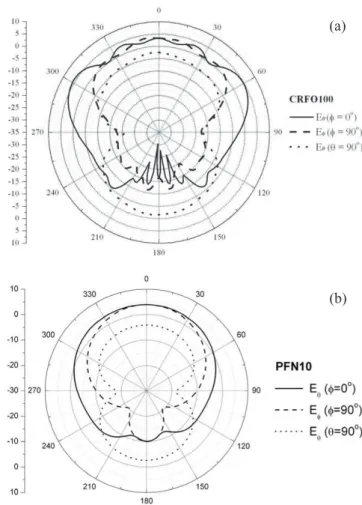
Figure 5. Simulated radiation pattern ofEθ(φ=0◦),Eφ(φ=90◦) andEθ(θ=90◦)for (a) CRFO100 and (b) PFN10.
The frequency for which the RL|S11|is minimum is then given in table1. According to the DR location with respect to the probe, this frequency is measured, and the variability range is also reported in table2. The observed variability is close to 1% and is much higher than that for the Hakki and Coleman method (classically 0.3% for εr [14]). It is worth mentioning that for a 50feeder, the antenna radiation is the best (S116=0) for a frequency close to the resonant frequency of the DR.
In table2are also indicated the minimum value of the RL for each DR. For the CRFO100 dielectric resonator an RL of about –43.4 dB was observed. For the PFN10 DRA, a value of about –46.9 dB was obtained. The DRA bandwidth is higher for the CRFO100 antenna (11.8%) and lower for the PFN10 (9.9%).
The frequency response of input impedance for the DRA antennas is plotted in figure 3 and shows good agreement between simulation and experimental data. In the numerical study, it was observed that the increase of the air gaps leads to a frequency shift upward and a decrease of the resistance at resonance. Such behavior has been explained in [13,14]. The resistance R of the first resonant frequency of each DRA is also indicated in table1and figure3. For the CRFO100 DRA, this value is about 114.02. For the PFN10 this value is about 98.3.
Phys. Scr.78(2008) 065704 M R P Santoset al good. However, one can note that the minimum of|S11|is not
always situated on the null reactance curve of the Smith chart (e.g. figure3(a)). ThereforeZ is not real atf0, as confirmed by the plot of Z given in figure3. Therefore the minimum of |S11|does not coincide exactly with the zero of the imaginary part ofZ.
A last result presented in table 1 is the value of the measured radiation efficiency. For the studied DRAs, the radiation efficiency is about 99.8%.
The calculated radiation patterns of theEθplane and the
Eφplane at resonant frequency for the PFN10 and CRFO100 samples are shown in figure 5. For the two dielectrics the radiation patterns are quite similar. The symmetry of the field patterns is related to the feed probe location atφ=0o. The obtained values for thex–z-plane (figure5(a)) show a broad, almost omnidirectional pattern. These results are in agreement with data reported in the literature [1].
4. Conclusions
In this paper, we did a study of the probe–feed cylindrical DRAs based on a new electroceramic composite, Pb(Fe0.5Nb0.5)O3 (PFN)/Cr0.75Fe1.25O3 (CRFO). The experimental and theoretical characteristics of the antenna, such as RL, bandwidth, input impedance and radiation patterns, are in good agreement. Numerical validation was done using HFSS software, taking into account the air gaps between the dielectric resonator and the metallic conductors. The PFN10 composite (10% PFN + 90% CRFO) presents the highest dielectric permittivity (9.9 at 4.44 GHz) and the lowest bandwidth (9.9%). The CRFO100 phase (100% CRFO) presents a dielectric permittivity of 8.35 at 4.67 GHz and a bandwidth of 11.8%. The Hakki–Coleman procedure was also used in this study. A dielectric permittivity of 8.35 (tanδ=1×10⁻³) at 7.94 GHz was obtained for CRFO. The PFN10 presents a dielectric permittivity of 10.17 (tanδ=4.9×10⁻³) at 7.05 GHz.
In summary, the performance of cylindrical DRAs based on a new matrix, PFN/CRFO, was examined. These measurements confirm the potential use of such materials for small DRAs.
Acknowledgments
This work was partly sponsored by the CAPES, FUNCAP and CNPq (Brazilian agencies) and the USAF and US Air Force Office of Scientific Research (AFOSR) (FA9550-08-1-0210).
References
[1] Luk K W and Leung K M 2002Dielectric Resonator Antennas
(Baldock, UK: Research Studies Press)
[2] Moulson A J and Herbert J M 1990Electroceramics: Materials Properties and Applications(London: Chapman and Hall)
[3] Majumder S B, Bhattacharyya S, Katiyar R S, Manivannan A and Dutta P 2006 Dielectric and magnetic properties of sol-gel-derived lead iron niobate ceramicJ. Appl. Phys.
99024108
[4] Freire F N A, Rocha H H B, Santos M R P, Fechine P B A, Pereira F M M, Sohn R S T M, Vasconcelos I F and Sombra A S B 2008 Structural studies of a new electroceramic composite: Pb(Fe0.5Nb0.5)O3(PFN)–Cr0.75Fe1.25O3(CRFO) J. Mater. Sci.4375
[5] Pietzak J, Maryanowska A and Leciejewicz J 1981Phys. Status Solidi.a6579
[6] Wang J T, Mbonye M K and Zang C 2003Int. J. Mod. Phys.B 173732
[7] Long S A, McAllister M W and Shen L C 1983 The resonant cylindrical dielectric cavity antennaIEEE Trans. Antennas Propag.31406
[8] Rocha H H B, Freire F N A, Santos M R P, Sasaki J M, Cordaro T and Sombra A S B 2008 Radio-frequency (rf) studies of the magneto-dielectric composites: Cr0.75Fe1.25O3
(CRFO)–Fe0.5Cu0.75Ti0.75O3(FCTO)Phys. B—Condens. Matter4032902
[9] Lejeune M and Boilot J P 1982Ceram . Int.399
[10] Hakki B W and Coleman P D 1960 A dielectric resonator method of measuring inductive capacities in the millimeter rangeIRE Trans. Microw. Theory Tech.
8402
[11] Kobayashi Y and Katoh M 1985 Microwave measurement of dielectric properties of low-loss materials by the dielectric rod resonator methodIEEE Trans. Microw. Theory Tech.
33586
[12] Grabovickic R 1999 Accurate calculations of geometrical factors of Hakki–Coleman shielded dielectric resonators
IEEE Trans. Appl. Supercond.94607
[13] Rocha H H B, Freire F N A, Costa R C S, Sohn R S T M, Orjubin G, Junqueira C, Cordaro T and Sombra A S B 2007 Dielectric resonator antenna: operation of the
magneto-dielectric composites Cr0.75Fe1.25O3(CRFO)/
Fe0.5Cu0.75Ti0.75O3(FCTO)Microw Opt. Technol. Lett.
49409
[14] Kajfez D and Guillon P (eds) 1986Dielectric Resonators (The Artech House Microwave Library)(Norwood, MA: Artech House)
[15] Mongia R K and Hartia P 1994 Dielectric resonator antennas—a review and general design relations for resonant frequency and bandwidthInt. J. Microw. Millim.-Wave Comput.-Aided Eng.4230
[16] Kishk A A, Glisson A W and Kajfez D 1993 Computed resonant frequency and far fields of isolated disks
IEEE Antennas Propogat. Soc. Int. Symp. Dig.
p 408
[17] Junker G P, Kishk A A, Glisson A W and Kajfez D 1994 Effect of air gap on cylindrical dielectric resonator antenna operating in TM01modeElectron. Lett.
3097
[18] Junker G P, Kishk A A, Glisson A W and Kajfez D 1994 Effect of an air gap around the coaxial probe exciting a cylindrical dielectric resonator antennaElectron. Lett.
303177
[19] Kiang J-F 2004Novel Tecnologies for Microwave and Millimeter-Wave Applications(Amsterdam: Kluwer) [20] Peng Z, Wang F and Yao X 2004 Dielectric resonator
antennas using high permittivity ceramicsCeram. Int.
301211