131
Journal of Engineering Science and Technology Review 4 (2) (2011) 131-134
Research Article
Liquid Crystal Bow-Tie Microstrip antenna for Wireless Communication Applications
B.T.P.Madhav1,*, VGKM Pisipati1, Habibulla Khan2, V.G.N.S Prasad2, K. Praveen Kumar3, KVL
Bhavani1 and M.Ravi Kumar4
1Liquid Crystal Research Center, K L University, Guntur, AP, India 2 R&D, Mother Theresa Institute of Science and Technology, Sattupalli, India
3Vani School of Engineering, Cheviture, India
4 Department of ECE, Sri Saradhi Institute of Engineering and Technology, Nuzvid, India
Received 19 February 2011; Revised 8 May 2011; Accepted 14 June 2011
___________________________________________________________________________________________
Abstract
In this paper we presented the design and analysis of Bow-Tie antenna on liquid crystal substrate, which is suitable for the Bluetooth/WLAN-2.4/WiBree/ZigBee applications. The Omni-directional radiation patterns along with moderate gain make the proposed antenna suitable for above mentioned applications. Details of the antenna design and simulated results Return loss, Input impedance, Radiation Patterns, E-Field, H-Field and Current Distributions, VSWR are presented and discussed. The proposed antenna is simulated at 2.4 GHz using Ansoft HFSS-11.
Keywords:
Bow-tie, Microstrip, LC
__________________________________________________________________________________________
1. Introduction
In recent years Microstrip antennas have been widely used in both theoretical research and engineering applications due to their light weight and thin profile configurations, low cost of fabrication, reliability, conformal structure and ease of fabrication [1-2]. In this paper bow-tie is designed at 2.4 GHz for wireless LAN applications. The bow-tie patch actually is the combination of imaginary image of two triangular patches which are fabricated on a single substrate [3-4]. Bow-tie antennas are mostly used in the communication scenario over the rectangular patches due to their compact nature [5-6].
Liquid crystal material is used as substrate in this proposed antenna designing. Liquid crystals are anisotropic materials which show both the properties of a crystal and a liquid. The nematic LCs are chosen for this operation because they are having best dielectric properties at microwave and mm-wave frequencies [7]. Liquid Crystals and Liquid crystal polymers are much cheaper than other available
dielectric materials. They are Low cost, low weight materials and they have low dielectric constant (2.9-3.2 for f < 105GHz) and low loss tangent (0.002-0.0045 for f < 105GHz). LCs have a unique property of low moisture absorption (water absorption <0.004%). So in general LC offers an excellent combination of electronic, thermal, mechanical and chemical properties that make it as a promising substrate for electronics packaging [8].
The liquid crystal substrate material is used in the making of this proposed antenna instead of RT-duroid [6]. The Liquid crystal substrate is having the dielectric constant of 2.97 and the loss tangent of 0.003.
1. Antenna Design
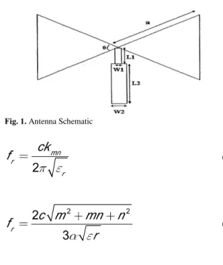
Figure (1) shows the dimensions of the microstrip bow-tie antenna. „a‟ is the side length and „θ‟ is the angle of the equilateral triangle. L1, L2, W1 and W2 are the dimensions of the matching network [8-9].
Fig. 1. Antenna Schematic
(1)
(2)
Where:
JOURNAL OF Engineering Science andTechnology Review
www.jestr.org
______________
* E-mail address: [email protected]
B.T.P.Madhav, VGKM Pisipati, Habibulla Khan, V.G.N.S Prasad, K. Praveen Kumar, KVL Bhavani and M.Ravi Kumar/ Journal of Engineering Science and Technology Review 4 (2) (2011) 131-134
132
f
r: is the resonance frequencyk
mn: is the resonating modesc: is the velocity of light in free space α: is the side length of the bow-tie strip
When triangular resonator is surrounded by a perfect magnetic wall then this expression will be valid.
Figure (2) shows the HFSS generated bow-tie antenna with the specifications applied to the design. The inner width is 1mm, outer width 18.8mm, arm length 17.1mm, gap port length 1mm, substrate thickness 1.58mm, substrate dimension along x-axis 40mm, substrate dimension along y-axis 60mm. The bows are connected to the microstrip feedline and the ground plane through a stub and mitered transition to match the bow-tie with the 50 Ω feedline.
Fig. 2. The HFSS generated bow-tie antenna
3. Results and Discussion
The return loss and VSWR are computed using Ansoft HFSS and they are shown in figure (3) and figure (4).
1.00 1.50 2.00 2.50 3.00 3.50 4.00 4.50
Freq [GHz] -15.00 -10.00 -5.00 0.00 d B(S(1 ,1 ))
Ansoft Corporation Return Loss Bow_Tie_Antenna_ADKv1
m1
m2
Curve Info dB(S(1,1)) Setup1 : Sw eep1 Name X Y
m1 1.0000 -0.0872 m2 2.3650 -14.4582
Fig. 3. Return Loss
1.00 1.50 2.00 2.50 3.00 3.50 4.00 4.50
Freq [GHz] 0.00 50.00 100.00 150.00 200.00 VSW R (p 1 )
Ansoft Corporation XY Plot 1 Bow_Tie_Antenna_ADKv1
m 1
m 2
Curve Info VSWR(p1) Setup1 : Sw eep1 Name X Y
m1 1.0000 199.3195 m2 2.3650 1.4669
Fig. 4. VSWR
The return loss of -14.45 and the VSWR 1.4669 is obtained at 2.4 GHz from the simulated results. The input impedance plot for the proposed antenna is shown in figure (5). The rms of 0.6760 and bandwidth of 1.9192 is obtained from the results. The 3D gain is shown in the figure (6).
0.20 0.40 0.60 0.80 5.00 2.00 1.00 0.50 0.20 5.00 -5.00 2.00 -2.00 1.00 -1.00 0.50 -0.50 0.20 -0.20 0.00 -0.00
5.00 2.00 1.00 0.50 0.20
5.00 -5.00 2.00 -2.00 1.00 -1.00 0.50 -0.50 0.20 -0.20 0.00 -0.000 10 20 30 40 50 60 70 80 90 100 110 120 130 140 150 160 170 180 -170 -160 -150 -140 -130 -120 -110 -100 -90 -80-70
-60 -50 -40 -30 -20 -10
Ansoft Corporation Input Impedance Bow_Tie_Antenna_ADKv1 Curve Info rms bandw idth(1, 0)
S(1,1)) Setup1 : Sw eep1 0.6760 1.9192
Fig. 5. Input impedance
Fig. 6. 3D gain
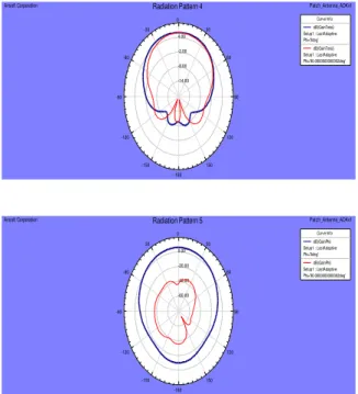
The co-polarized (EФ) and cross-polarized (Eθ) far-field radiation patterns for the proposed antenna is computed at 2.4 GHz. Figure (7) shows the radiation patterns of the bow-tie antennas.
-14.00 -8.00 -2.00 4.00 90 60 30 0 -30 -60 -90 -120 -150 -180 150 120
Ansoft Corporation Radiation Pattern 4 Patch_Antenna_ADKv1
Curve Info dB(GainTotal) Setup1 : LastAdaptive Phi='0deg'
dB(GainTotal) Setup1 : LastAdaptive Phi='90.0000000000002deg' -60.00 -40.00 -20.00 0.00 90 60 30 0 -30 -60 -90 -120 -150 -180 150 120
Ansoft Corporation Radiation Pattern 5 Patch_Antenna_ADKv1
Curve Info dB(GainPhi) Setup1 : LastAdaptive Phi='0deg'
B.T.P.Madhav, VGKM Pisipati, Habibulla Khan, V.G.N.S Prasad, K. Praveen Kumar, KVL Bhavani and M.Ravi Kumar/ Journal of Engineering Science and Technology Review 4 (2) (2011) 131-134
133 -54.00
-38.00 -22.00 -6.00
90 60 30 0 -30
-60
-90
-120
-150 -180
150 120
Ansoft Corporation Radiation Pattern 6 Bow_Tie_Antenna_ADKv1 Curve Info max min pk2pk avg dB(GainTheta)
Setup1 : LastAdaptive Phi='0deg'
-47.23-65.47 18.24 -53.73 dB(GainTheta)
Setup1 : LastAdaptive Phi='90.0000000000002deg'
2.24 -25.22 27.45 -4.08
Fig. 7. Gain-total, gain phi, gain theta
Fig. 8. Gain-Theta
Fig. 9. Gain – Phi
The radiation patterns give the good agreement between the simulated and the measured results. 3D radiation pattern results for the proposed antenna using concerto software is given in the figure (8) and figure (9). The antenna parameters are simulated from the HFSS are listed and shown in table (1).
Table 1. Antenna Parameters
Quantity Value
Max U 0.12471 w/sr
Peak directivity 1.669
Peak gain 1.6731
Peak realized gain 1.5672
Radiated power 0.939 w Accepted power 0.93675 w Incident power 1 w Radiation efficiency 1.0024 Front to back ratio 1.0308
4. Field Distribution
The 3D field distribution plots give the relationship between the co-polarization (desired) and cross-polarization (undesired) components. Moreover it gives a clear picture as to the nature of polarization of the fields propagating through the patch antenna. Figure (10) and (11) clearly shows the microstrip bow-tie antenna E-field and H-field distribution.
Fig. 10. E-Field Distribution
Fig. 11. H-Field Distribution
Mesh generation is the practice of generating a polygonal or polyhedral mesh that approximates a geometric domain to the highest possible degree of accuracy. The term "grid generation" is often used interchangeably. Typical uses are for rendering to a computer screen or for physical simulation such as finite element analysis or computational fluid dynamics. The triangulated zones in the mesh shown in figure (12) indicate the points in the grid where the current distributed is concentrated.
B.T.P.Madhav, VGKM Pisipati, Habibulla Khan, V.G.N.S Prasad, K. Praveen Kumar, KVL Bhavani and M.Ravi Kumar/ Journal of Engineering Science and Technology Review 4 (2) (2011) 131-134
134 S-parameters are calculated from the average current distribution of the cross section, and thus the exact current distribution is not required to be precise.
5. Conclusions
Experimental implementation of this work involves the LC dielectric characterization at microwave frequencies, which has been investigated. The measured parameters were also in good agreement with the simulated results. The results shown here demonstrate the applicability of Liquid crystals for the development of low-cost, lightweight antennas on “all-package” solution for future wireless communication and remote sensing systems. The investigation has been limited mostly to theoretical study
due to lack of distributive computing platform. Detailed experimental studies can be taken up at a later stage to find out a design procedure for balanced amplifying antennas.
Ackmowledgement
The authors B.T.P.Madhav, Prof.VGKM Pisipati and Prof. Habibulla Khan express their thanks to the management of K L University and Department of Electronics and Communication Engineering for their support. Further, VGKM Pisipati acknowledges the financial support of Department of Science and Technology through the grant No.SR/S2/CMP-0071/2008.
______________________________
References
1. Constantine A. Balanis; Antenna Theory, Analysis and Design, John Wiley & Sons Inc. 2nd edition. 1997.
2. Kiminami, K. Hirata, A., Shiozawa, “Double-sided printed bow-tie antenna for UWB communications”, Antennas and Wireless Propagation Letters, IEEE, Issue Dec.2004, Volume: 3 Issue: 1, 152 – 153.
3. Rahim, M.K.A. Abdul Aziz, M.Z.A.,Goh, C.S, “Bow-tie microstrip antenna design” IEEE 7th Malaysia International Conference on Communication., 2005
4. Carlos Moreno de Jong van Coevorden, Amelia Rubio Bretones, “GA Design of a Thin-Wire Bow-Tie Antenna for GPR Applications”, IEEE Transactions On Geoscience And Remote Sensing, Vol. 44, No. 4, April 2006
5. Yu-De Lin and Syh-Nan Tsai “Coplanar waveguide fed unipolar bow-tie antenna, “IEEE Trans. On antennas and propagation, vol. 45, issue 2, pp .305-306, feb-1997.
6. Z. Guiping, A.A Kishk, A.B Yakovelev and A.W Glisson, “A Broadband printed bow-tie antenna with a simplified feed, “IEEE Ant. And propagation society international symposium, vol.4, pp.4024-4027, 20-25 June 2004.
7. A.A.Lestari, A.G. Yarovoy and L.P Ligthart, “Adaption capabilities of wire bow-tie antenna for ground penetrating radar, “IEEE Antennas and Propagation society International Symposium, vol 2, pp 564-567, 8-13 July 2001
8. G. Zou, H. Gronqvist, J. P. Starski and J. Liu, “Characterization of Liquid Crystal Polymer for High Frequency System-in-Package Applications”, IEEE Transactions on Advanced Packaging, 2002.
9. K. F. Lee, Ed., Advances in Microstrip and Printed Antennas, John Wiley, 1997.