ABSTRACT
Mechanical testing of thin-walled zirconia
abutments
!1"#$%& !'(!2,3, Estevam A. BONFANTE
1- DDS, Private Practice, Rome, Italy.
2- DDS, MS, BS, MsMtE, PhD, Assistant Professor, Department of Biomaterials and Biomimetics, New York University College of Dentistry, New York, USA. 3- Director for Research – Department of Periodontology and Implant Dentistry, New York University College of Dentistry, New York, USA.
4- DDS, MS, PhD, Assistant Professor, Postgraduate Program in Dentistry, School of Health Sciences, UNIGRANRIO University, Duque de Caxias, RJ, Brazil.
)*++$)** Estevam Augusto Bonfante - Rua Prof. José de Souza Herdy, 1.160 - 25 de Agosto - Duque de Caxias, RJ, Brazil, 25071-202 - Phone: 55 (14) 8153-0860 - Fax: 55(14) 3234-2566 - [email protected]
-45)6)4$7"89):);)54)";;)):);)54)"
A
lthough the use of zirconia abutments for implant-supported restorations has gained momentum with the increasing demand for esthetics, little informed design rationale has been developed to characterize their fatigue behavior under different clinical scenarios. However, to prevent the zirconia from fracturing, the use of a titanium connection in bi-component aesthetic abutments has been suggested. Objective: Mechanical testing of customized thin-walled titanium-zirconia abutments at the connection with the implant was performed in order to characterize the fatigue behavior and the failure modes for straight and angled abutments. Material and Methods: Twenty custom-made bi-component abutments were tested according to ISO 14801:2007 either at a straight or a 25° angle conditions at 20°C±5°C. Mean values and standard deviations were calculated for each group. All comparisons were performed by t-tests assuming unequal variances. The level ! " # light and then in a scanning electron microscope. Results: Straight and angled abutments mean maximum load was 296.7 N and 1,145 N, the dynamic loading mean Fmax was 237.4$ %&' $( ) $ ! * *# * * %+ + / ! * ; * application, whereas in the straight abutments, fractures were located coronally and close to the thinly designed areas at the cervical region. Conclusion: Angled or straight thin-walled zirconia abutments presented similar Fmax under fatigue testing despite the different
bending moments required for fracture. The main implication is that although zirconia angled or straight abutments presented similar mechanical behavior, the failure mode tended to be more catastrophic in straight (fracture at the cervical region) compared to angled abutments.
Key words: Dental implants. Zirconium. Dental implant-abutment design. Fatigue
INTRODUCTION
Since osseointegration became a safe treatment modality in dentistry, several designs of implant-abutment systems have been available for clinical use, with a plethora of data being produced on titanium as the main abutment material. Historically, the external hexagon connection was designed to provide an engagement method for implant
placement and anti-rotational feature for single-unit prosthesis, and is likely the functioning system with the longest clinical follow-up15,20,21. Despite the high
In essence, implant abutments can be made of ceramic (yttrium tetragona zirconia polycristals, i.e. Y-TZP) or titanium (commercially pure or alloyed) and can also be prefabricated or customized. The standardization of the prefabricated abutments may present a limitation to the establishment of !( cases where a discrepancy exists between the implant and the crown diameter. In such cases, the * * ! the crown, which could result in unfavorable core/ porcelain thickness ratios. A way to overcome this issue is the use of a customized abutment that will ) ! by the abutment instead of the crown13.
Customized-zirconia abutments have shown comparable survival rates relative to titanium abutments17,22.
However, the internal connection between a zirconia customized abutment and the implant continues to be a mechanical challenge. Thus, to prevent the zirconia from fracturing at the connection, the use of a titanium connection in bi-component aesthetic abutments have been suggested2.
Among the concerns regarding the use of CAD/CAM customized-zirconia abutments is their unknown mechanical performance in clinical situations where the implant positioning and occlusal restraints result in thin abutment walls that may negatively influence the long-term prosthetic functional outcome3. Although the
bucco-lingual positioning and angulation of the implant is ! ( there is a need to compensate non-ideal implant positioning with angled customized abutments.
Whereas, the mechanical property of customized
titanium abutments may be less affected by the resulting wall thinning, due to its ductile nature, the same assumption may not hold true for brittle ceramic abutments. Therefore, this study evaluated the mechanical performance of thinned zirconia abutments at the connection, in an attempt to simulate 2 implantation scenarios in terms of inclination. In fact, in the anterior aesthetic zone, according to the different available bone conditions, implant insertion may require straight (mostly in canine and bicuspid zones) or inclined (incisor zones) abutments.
The tested null hypothesis was that a straight bi-component abutment does not present a different fatigue life compared to an angled one.
MATERIAL AND METHODS
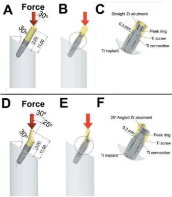
Twenty custom-made zirconia abutments ? @ B( E( G according to Norm UNI EN ISO 14801:2007
(Dynamic fatigue test of endosseous dental or a 25° angle relative to the implant long axis ) (Figures 1A and B). In order to evaluate the abutments under a worst case scenario, an industrially imposed minimum thickness of 0.3 mm at the connection area with the implant was chosen.
Q !V was inserted in a prefabricated rigid Plexiglas® clamping device. Individualized
zirconia abutments were cemented on a titanium !V screw according to the manufacturer’s instructions: after cleaning with alcohol, the zirconia abutment was cemented onto the titanium connection (All ? ( ? @ B( E( G The mixed cement was applied onto the contact part of the titanium connection. The zirconia abutment ! Q remaining cement was removed immediately with steam and after polymerization, the excess cement was removed.
A PEEK (polyetherketone) ring was used for stress distribution at the zirconia/titanium interface interposed between the zirconia abutment and
Figure 1-
retaining screw(Figure 2).
For mechanical testing, single load to fracture
(SLF) was performed (6027, G( [?/
each), and the mean values were used to calculate
the maximum load (Fmax). The loading geometry
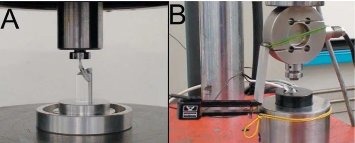
!V * [$G \$ G?] &^_%' * the SLF and dynamic loading tests. The implant/ abutment system was positioned with its long axis inclined at a 30°±1° angle relative to the loading direction. The dimensions of the indenter resulted in
a distance of l ` of
the hemisphere to the clamping plane (Figure 3a). A hemispherical indenter was used for the load application. Eighty percent of the Fmax was used as a starting load value for the dynamic testing, which used an uni-axial testing equipment (FPF, Italsigma, Italy), with a 2.000 N load cell (TSTM, AeP, Italy) and an extensometer (2620-601, Instrom, USA) (Figure 3b). Fatigue was conducted at 15 Hz for 5 million cycles in dry conditions at 20°C±5°C. The bending moment was calculated as follows:
(1)
! * V 30°), and F is the force expressed in newtons.
Failed samples were inspected in a polarized-light microscope (MZ-APO, Carl Zeiss Micro Imaging, Thornwood, NY, USA) and then in a scanning electron microscope at an acceleration voltage of 10 Kv (XVP®, Evo 50, Carls Zeiss AG, Oberkochen,
Germany).
Statistical analysis
Mean values and standard deviations were calculated for each outcome variable (static and dynamic tests) as a function of the straight and inclined abutment groups.
All comparisons were performed by t-test assuming unequal variances [SigmaStat 3.0 (SPSS Inc., Chicago, IL, USA)]. The level of statistical
! "
RESULTS
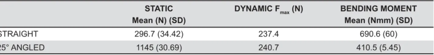
The mean Fmax value for SLF, dynamic loading are presented in Table 1, as well as the bending moments required for fracture.
$ ! observed between the straight and angled
bi-Figure 2- Components of the custom-made abutment composed by an individualized zirconia abutment cemented on a titanium connection linked to the implant using a titanium screw. A peek ring was used for stress distribution at the zirconia/ titanium interface interposed between the zirconia abutment and retaining screw
* * %+ + / difference in the bending moment required for *
the point of load application, whereas in the straight abutments fractures were located coronally and close to the thinly designed areas at the cervical region (Figure 4).
DISCUSSION
The present study simulated clinical scenarios where customized zirconia abutments presented the thinnest possible section at the connection ( ! mechanical response, according to our SLF testing. However, when evaluated under a more clinically realistic loading scenario, (fatigue) Fmax were not significantly different between the groups, but bending moments for fracture were higher for the straight relative to the angled abutments. Such a
result was not expected considering the differences in the lever scenario created for both groups, but may be accounted by the difference in the moment of inertia between the two designs.
The resulting failure modes where the straight abutments showed fractures at the cervical region compared to fractures at the point of load application * bending moments for both groups. From a clinical standpoint, although both scenarios may fail at similar time points, it can be speculated that in a restoration supported by a thinned angled zirconia abutment, the crown is more likely to shield the functional area receiving the load compared to a thinned straight abutment. Such an assumption warrants further investigation. The bending * ! compared to values observed in the literature18.
This could be related to the double zirconia/titanium anchorage system.
As to the testing methods available for the evaluation of different implant-abutment system !( ) ) * *( as the single load to fracture1, the use of fatigue
followed by the application of a static load until fracture5,11, the staircase method16, fatigue limit
(ISO 14801:2007), step-stress accelerated life testing6, and others. While the ISO 14801 was
created in 2003 and revised in 2007, with the aim of standardizing the testing procedures and data presentation in the fatigue of dental implants, it has been shown that the results produced by such a method should be interpreted with caution. The wide range of testing parameters allowed in the ISO 14801:2007 regarding the testing frequency (2 to 15 Hz), environment (water or dry when testing above 15 Hz) and amount of cycles (2 or 5 million, depending on the chosen frequency) have shown that a very different failure probability distribution may result10, as well as failure modes12.
Whereas, the present study utilized the highest end of the speed scale allowed by the norm, especially to optimize the machine testing time, potential differences in the fatigue limit and failure modes when testing in 2 Hz in water may exist and warrant future investigation. It may be suggested that, while attending industry requirements for implants quality assurance and control, the ISO 14801:2007 testing methodology may likely continue to be developed
6) Representative polarized light and scanning electron microscope micrographs of abutment samples failed during fatigue. A) Straight abutment group in a frontal view depicting that fractures occurred coronally at B) thinly designed areas (pointer) mostly close to the base of the abutment, as observed in this occlusal view. C) In the angled group, fracture occurred at the point of load application involving D) thinly designed areas (pointer), as observed in this occlusal view
-HHI Mean (N) (SD)
:Q8I6max (N) BENDING MOMENT Mean (Nmm) (SD)
STRAIGHT 296.7 (34.42) 237.4 690.6 (60)
25° ANGLED 1145 (30.69) 240.7 410.5 (5.45)
Table 1- Mean values for mechanical testing of the straight and 25° angled zirconia abutment groups
as observed from 2003 to the currently advocated version10,12.
As generally reported and also in agreement with our testing results, the discrepancy in values arising from the static relative to the dynamic testing and the clinical relevance of each, should be acknowledged. If the selection of a system was based on the static test results, which do not simulate physiological loading scenarios where repetitive, lower load cycling is the chief mechanism leading to failure, most systems would be suitable irrespective of the area of application (molar or incisor). With static loading, materials will commonly fail at loads higher than those in fatigue. The mechanisms of subcritical crack growth that should be simulated in testing include those that operate in use-related failures which are stress corrosion and cyclic fatigue14. In this study, static testing was only
performed to provide load values for subsequent fatigue testing. Fatigue can provide more effective ways of simulating failures observed clinically4.
Considering that the reported maximal bite force in the incisor area may vary from 108 N8 to 190 N7,9,
the Fmax fatigue loads observed for both thin-walled straight or angled zirconia abutments are above the physiologic range. Therefore, in esthetically demanding areas, zirconia abutments may be indicated especially when thin peri-implant soft tissues are present19. Although no direct comparison
was performed with titanium abutments, short-term clinical studies and systematic reviews point toward similar success rates for both materials and *) ) restorative system9. Future long-term clinical studies
are warranted.
CONCLUSION
The postulated null hypothesis that a straight bi-component abutment would not present different Fmax than an angled abutment under fatigue was accepted. However, failure modes differed between the groups.
ACKNOWLEDGEMENTS
Q ) ! ( either directly or indirectly, in the products listed in the study. We highly appreciated the skills and commitment of Eng. Enrico Babetto for the technical support and Dr. Audrenn Gautier and Dr. Henry Canullo in the supervision of the study.
REFERENCES
1- Al-Omari WM, Shadid R, Abu-Naba'a L, El Masoud B. Porcelain fracture resistance of screw-retained, cement-retained, and screw-cement-retained implant-supported metal ceramic posterior crowns. J Prosthodont. 2010;19:263-73.
2- Canullo L. Clinical outcome study of customized zirconia abutments for single-implant restorations. Int J Prosthodont. 2007;20:489-93.
3- Canullo L, Morgia P, Marinotti F. Preliminary laboratory evaluation of bicomponent customized zirconia abutments. Int J Prosthodont. 2007;20:486-8.
4- Coelho PG, Bonfante EA, Silva NR, Rekow ED, Thompson VP. Laboratory simulation of Y-TZP all-ceramic crown clinical failures. J Dent Res. 2009;88:382-6.
5- Dittmer MP, Dittmer S, Borchers L, Kohorst P, Stiesch M. G # abutment complex before and after cyclic mechanical loading. J Prosthodont Res. 2012;56:19-24.
6- Freitas AC Jr, Bonfante EA, Rocha EP, Silva NR, Marotta L, Coelho PG. Effect of implant connection and restoration design (screwed vs. cemented) in reliability and failure modes of anterior crowns. Eur J Oral Sci. 2011;119:323-30.
7- Hagberg C. Assessment of bite force: a review. J Craniomandib Disord. 1987;1:162-9.
8- Helkimo E, Carlsson GE, Helkimo M. Bite force and state of dentition. Acta Odontol Scand. 1977;35:297-303.
9- Helkimo E, Ingervall B. Bite force and functional state of the masticatory system in young men. Swed Dent J. 1978;2:167-75. # B( G ; failure under cyclic fatigue conditions. Dent Mater. 2009;25:1426-32.
11- Kohal RJ, Wolkewitz M, Tsakona A. The effects of cyclic loading and preparation on the fracture strength of zirconium-dioxide implants: an in vitro investigation. Clin Oral Implants Res. 2011;22:808-14.
12- Lee CK, Karl M, Kelly JR. Evaluation of test protocol variables for dental implant fatigue research. Dent Mater. 2009;25:1419-25. 13- Marchack CB. A custom titanium abutment for the anterior single-tooth implant. J Prosthet Dent. 1996;76:288-91.
14- Paris P, Erdogan F. A critical analysis of crack propagation laws. J Basic Eng. 1963;85:528-34.
15- Priest G. Single-tooth implants and their role in preserving remaining teeth: a 10-year survival study. Int J Oral Maxillofac Implants. 1999;14:181-8.
16- Ribeiro CG, Maia ML, Scherrer SS, Cardoso AC, Wiskott HW. Resistance of three implant-abutment interfaces to fatigue testing. J Appl Oral Sci. 2011;19:413-20.
17- Sailer I, Philipp A, Zembic A, Pjetursson BE, Hämmerle CH, Zwahlen M. A systematic review of the performance of ceramic and * !V Clin Oral Implants Res. 2009;20:4-31.
18- Sailer I, Sailer T, Stawarczyk B, Jung RE, Hämmerle CH. In vitro of zirconia abutments with internal and external implant-abutment connections. Int J Oral Maxillofac Implants. 2009;24:850-8. 19- Sailer I, Zembic A, Jung RE, Hämmerle CH, Mattiola A. _ decision between titanium and zirconia abutments in anterior regions. Eur J Esthet Dent. 2007;2:296-310.
20- Scholander S. A retrospective evaluation of 259 single-tooth replacements by the use of Brånemark implants. Int J Prosthodont. 1999;12:483-91.
21- Wannfors K, Smedberg JI. A prospective clinical evaluation of different single-tooth restoration designs on osseointegrated implants. A 3-year follow-up of Brånemark implants. Clin Oral Implants Res. 1999;10:453-8.