Numerical Model and Seismic
Structural Analysis of the
Lamberti Tower
DECLARATION
Name: Andrea Tassello
Email: [email protected]
Title of the Msc Dissertation:
NUMERICAL MODEL AND SEISMIC STRUCTURAL ANALYSIS OF THE LAMBERTI TOWER
Supervisor(s): Prof. Paulo José Brandão Barbosa Lourenço
Year: 2013
I hereby declare that all information in this document has been obtained and presented in accordance with academic rules and ethical conduct. I also declare that, as required by these rules and conduct, I have fully cited and referenced all material and results that are not original to this work.
I hereby declare that the MSc Consortium responsible for the Advanced Masters in Structural Analysis of Monuments and Historical Constructions is allowed to store and make available electronically the present MSc Dissertation.
University: University of Minho
Date: July, 12th, 2013
ACKNOWLEDGEMENTS
I would like to thank the Master SAHC Consortium for selecting me to be part of this program and for the scholarship that was given to me.
I want to give a particular acknowledgement to my thesis supervisor Professor Paulo B. Lourenço, at Universidade de Minho. He was always available for solving my doubts and answer my questions despite of his multiples occupations.
My gratitude goes out to each of the professors and guest lecturers of the course. In particular, I recognize the efforts of Professor Pere Roca and Luca Pelà, who perfectly organized and guided the courses in Barcelona.
My thanks also goes to all the PhD students who helped throughout my coursework and dissertation. In particular, from the University of Padova I recognize Filippo Lorenzoni. From the University of Minho I especially would like to thank Ana Arùjo, who was always available and she helped in using the software DIANA and solving many doubts. I want also to give a particular acknowledgement the PhD student Joao Leite. He helped me to process the data of the dynamic identification test and he gave me many advices. I also feel incredibly fortunate to have had such wonderful classmates in Barcelona and Guimaraes. Them more than anything has made the course so unique and enjoyable.
ABSTRACT
Masonry towers are relevant typology buildings in the Italian built heritage, due to their widespread in the territory and the important historic value that they have. The history shows emblematic examples of the consequences of their structural vulnerability. In fact only a few of these structures survived until today and the majority of the ancient high towers in Italy are no longer present. The high structural risk of high masonry tower justified detailed studies and carefully planned remedial measures.
The present Master Thesis project focuses on the Lamberti Tower, a medieval masonry tower with a height of 84 m located in Verona, northern Italy. The work starts by describing the research that was already done on the tower and that was made available. Then, a numerical model of the structure was built to be able to simulate its behavior.
Two different models were prepared with 3D elements based on the Finite Element Method. In the specific case of the towers, the simplicity of the structure allows to create models that replicate well their thickness and the materials present without using too many elements. For this reason, a simple model composed by 3D composite beams was made, which allows future analysis using time history analysis. The second model is more detailed and was defined using 3D solid elements, which make it mode adequate for static analysis.
In order to update the Finite Element (FE) models dynamic identification has been carried out on May 29th, 2013. The aim of the acquisitions was to define the modal parameters (natural frequencies and mode shapes) of the building. The numerical results, obtained from the structural eigenvalue analysis of the solid model, were compared with the experimental values and it was observed that the first adopted physical properties were not acceptable, possibly due to the boundary conditions. For this reason a modal updating, for the 3D solid mesh, was performed to validate the models and the modal assurance criterion (MAC) was calculated. The model built showed a behavior similar to the real tower, but a deeper investigation is recommended, especially for what concern the material parameters of the different types of masonry that compose the structure and the boundary conditions
.
At the end of this work the 3D beam model and 3D the solid model were used for a subsequent non-linear static (pushover) analysis for a first seismic assessment purpose. The strain distribution found showed that when the tower reaches considerable displacements, a failure mechanism with rotation at the base of the tower was clearly defined.
RESUMO
Torres são edifícios de alvenaria tipologia relevantes no património edificado italiano, devido à sua ampla no território e do valor histórico importante que eles tenham. A história mostra exemplos emblemáticos das conseqüências de sua vulnerabilidade estrutural. De facto, apenas algumas destas estruturas e sobreviveram até hoje a maioria das torres altas antigos em Itália não estão mais presentes. O alto risco estrutural de alta torre de alvenaria justifica estudos detalhados e cuidadosamente planejado de medidas correctivas.
A presente Dissertação de Mestrado projecto centra-se na Torre Lamberti, uma torre medieval de alvenaria com uma altura de 84 m localizado em Verona, norte da Itália. O trabalho começa por descrever a pesquisa que já foi realizado na torre e que foi disponibilizado. Em seguida, um modelo numérico de a estrutura foi construída para ser capaz de simular o seu comportamento.
Dois modelos diferentes foram elaboradas com elementos 3D baseados no Método dos Elementos Finitos. No caso específico, as torres, a simplicidade da estrutura permite que a criação de modelos que replicam bem a sua espessura e os materiais presentes, sem o uso de muitos elementos. Por esta razão, um modelo simples, composta por vigas mistas 3D foi efectuada, o que permite uma futura análise utilizando a análise de histórico de tempo. O segundo modelo é mais detalhado e foi definida utilizando elementos sólidos 3D, que o tornam adequado para a análise do modo estático.
Para atualizar o Elementos Finitos (FE) modelos de identificação dinâmica foi realizada em 29 de maio de 2013. O objetivo das aquisições foi para definir os parâmetros modais (freqüências naturais e modos de vibração) do edifício. Os resultados numéricos obtidos a partir da análise do modelo sólido eigenvalor estrutural, foram comparados com os valores experimentais e observou-se que as primeiras propriedades físicas adoptadas não foram aceitáveis, possivelmente devido às condições de contorno. Por esta razão, foi realizado um modal de atualização, para a malha 3D sólido, para validar os modelos ea garantia modal critério (MAC) foi calculado. O modelo construído apresentou um comportamento semelhante ao real torre, mas uma investigação mais profunda é recomendada, especialmente para os que dizem respeito aos parâmetros materiais dos diferentes tipos de alvenaria que compõem a estrutura e as condições de contorno.
No final deste trabalho, o modelo 3D de feixe e do modelo sólido em 3D foram utilizados para uma análise não linear estático (influenciável) subsequente para um primeiro objectivo sísmica. A distribuição da tensão encontrada mostraram que quando a torre atinge deslocamentos consideráveis, um mecanismo de falha com rotação na base da torre foi claramente definida.
SOMMARIO
Titolo: MODELLO NUMERICO E ANALISI SISMICA DELLA TORRE DEI LAMBERTI
Le torri in muratura rappresentano una tipologia strutturale importante nel patrimonio architettonico italiano, per l’ampia diffusione sul territorio e per il valore storico che rivestono. In passato vi sono stati esempi emblematici della loro vulnerabilità strutturale. Solo alcune di queste costruzioni, infatti, sono sopravvissute fino ad oggi e la maggior parte delle prominenti torri medievali sono scomparse. L’elevato rischio strutturale delle torri giustifica l’elevato numero di studi effettuati e delle avanzate misure d’intervento e di consolidamento pianificate.
Il presente progetto di tesi di Master si focalizza sulla Torre dei Lamberti, una torre medievale in muratura alta 84 m e ubicata nel centro storico della città di Verona, in Italia settentrionale. Nella parte iniziale dell’elaborato vi è la descrizione di una relazione precedente realizzata e resa disponibile da uno studio ingegneristico italiano. Dopo una descrizione dello stato dell’arte della Torre è stato definito un modello numerico per simulare il comportamento della struttura.
Due differenti modelli sono stati elaborati con elementi 3D basati sul metodo agli elementi finiti. Nello specifico caso delle torri, la relativa semplicità strutturale permette di creare modelli che replicano in modo efficace il loro spessore e le loro caratteristiche dei materiali senza l’uso di troppi elementi. Per questa ragione, un semplice modello costituito da elementi beam 3D è stato realizzato, il quale permette di eseguire future analisi dinamiche non lineari. Il secondo modello, più dettagliato, è stato definito usando elementi solidi 3D, il che lo rende più adeguato per delle analisi strutturali statiche.
Con lo scopo di affinare i vari modelli agli elementi finiti (FE) ottenuti, il giorno 29 Maggio 2013 sono state effettuate della prove di identificazione dinamica sulla Torre dei Lamberti. Lo scopo delle acquisizioni è stato quello di definire i parametri modali della struttura (frequenze proprie e funzioni di forma). I risultati numerici, ottenuti dall’analisi agli autovalori del modello con elementi brick, sono stati confrontati con i valori sperimentali ed è stato possibile osservare che le proprietà fisiche inizialmente adottate non erano accettabili, probabilmente per le condizioni al contorno considerate. Per questa ragione, è stata eseguita una calibrazione sulla mesh del modello 3D con elementi brick per validare i differenti modelli, ed è stato infine calcolato il “modal assurance criterion” (MAC). Il modello realizzato ha mostrato un comportamento simile a quello reale della torre, anche se sarebbe consigliata un’indagine più approfondita, soprattutto per quanto concerne i parametri dei materiali che costituiscono i diversi tipi di muratura della struttura e pure per le condizioni al contorno della torre.
La distribuzione delle deformazioni ottenuta ha evidenziato che, quando la struttura raggiunge spostamenti considerevoli, è chiaramente individuato un meccanismo di rottura con una rotazione alla base della torre.
TABLE OF CONTENTS
... 7
1. INTRODUCTION
... 9
2. MASONRY TOWERS
2.1
!
THE COLLAPSE OF THE CIVIC TOWER OF PAVIA!...!10
!
2.2
!
ANALYSIS OF CRACKS AND DAMAGES!...!12
!
2.3
!
SAFETY ASSESSMENT METHODS!...!14
!
2.3.1
!
SIMPLIFIED VERIFICATIONS!...!15
!
2.3.2
!
ANALYTICAL VERIFICATIONS!...!15
!
2.3.3
!
MATHEMATICAL ADVANCED MODELS!...!18
!
2.4
!
REPAIRING AND STRENGTHENING TECHNIQUES!...!20
!
2.4.1
!
TIE RODS!...!20
!
2.4.2
!
BASE ISOLATION!...!22
!
2.4.3
!
OTHER TECHNIQUES!...!22
!
... 25
3. LAMBERTI TOWER
3.1
!
GEOMETRY!...!26
!
3.2
!
CHARACTERISTICS OF THE SOIL!...!27
!
3.3
!
CHARACTERISTICS OF THE MATERIALS!...!27
!
3.4
!
DESCRIPTION OF THE BELLS!...!28
!
3.5
!
PREVIOUS DYNAMIC ANALYSIS RESULTS AND INSPECTIONS!...!30
!
4.
DYNAMIC IDENTIFICATION
... 35
4.1
!
MODAL ANALYSIS!...!36
!
4.1.1
!
TEST PLANNING!...!36
!
4.1.2
!
EXPERIMENTAL RESULTS!...!40
!
5.
DEFINITION OF THE NUMERICAL MODEL ... 43
5.1
!
THREE DIMENSIONAL BEAM MODEL!...!43
!
5.2
!
EIGENVALUE ANALYSIS OF THE BEAM MODEL!...!45
!
5.3
!
THREE DIMENSIONAL SOLID MODEL!...!47
!
5.4
!
EIGENVALUE ANALYSIS OF THE SOLID MODEL!...!51
!
5.5
!
MODEL UPDATING FOR THE 3D FE SOLID MESH!...!52
!
5.5.1
!
MODIFICATION OF THE ELASTIC MODULUS!...!54
!
5.5.2
!
LATERAL SPRINGS!...!56
!
5.6
!
NON-LINEAR STATIC ANALYSIS (PUSHOVER)!...!60
!
5.6.1
!
DEFINITION OF MASONRY CONSTITUTIVE LAW AND NON-LINEAR MATERIAL
PROPERTIES!...!60
!
5.6.2
!
RESULTS!...!62
!
6. CONCLUSIONS AND
RECOMMENDATIONS FOR EVENTUAL FUTURE STUDIES
... 67
... 69
7. REFERENCES
TABLE OF FIGURES
Figure 1 – Mechanisms for towers: a) kinematism 1; b) kinematism 2; c) kinematism 4; d) kinematism 5;
e) kinematism 6 (Doglioni, 1994).!...!13
!
Figure 2 – Mechanisms of bell towers considering the belfry: a) kinematism 1, b) kinematism 2, c) e d) kinematism 3 (Doglioni at al., 1994).!...!14
!
Figure 3 – Seismic damages of isolated towers after the earthquake in 1997: a) different pattern of damage; b) example of Tiponzo Tower in Cerreto di Spoleto (Marchetti et al., 2004).!...!14
!
Figure 4 – Collapse mechanisms for bell towers (Linee Guida, 2010): a) tower, b) belfry, c) roof!...!16
!
Figure 5 – Leaning towers: a) Medieval Tower of Peterhouse, Cambridge; b) inclined parallelepiped; c) parallelepiped with generic inclination; d) crack development (Heyman, 1992).!...!16
!
Figure 6 – Leaning towers: critical angle of inclination for different values of the ratio base/height (Heyman. 1992).!...!18
!
Figure 7 – Different types of reinforcing rings in the bell-tower of Duomo di Monza: a) A1 type; b) A2 type; c) B type; d) C type; e) F type!...!21
!
Figure 8 – Reinforcing rings in the Civic Tower of Vicenza: a) external view; b) scheme; c) new anchor element and scheme of the “C” type of reinforcing ring.!...!21
!
Figure 9 – Seismic strengthening: a) reticular System with FRP, bell-tower of S. Lucia (Cosenza et al., 2007); b) devices SMAD, bell-tower of S. Giorgio (Indirli, 2000); c) devices SMAD, Capocci Tower (Abruzzese et al., 2004); devices SMAD (Abruzzese et al., 2004).!...!23
!
Figure 10 – Lamberti Tower, picture from the square “Piazza Erbe”!...!25
!
Figure 11 – Front and back of Lamberti Tower!...!26
!
Figure 12 – Section of Lamberti Tower at the level of the courtyard “mercato vecchio” and on the right section of the top of the tower!...!27
!
Figure 13 – Samples of the soil survey of Lamberti Tower!...!27
!
Figure 14 – Section of Lamberti Tower with the location of the two bells!...!28
!
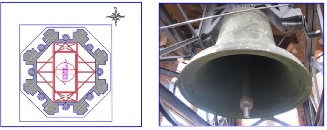
Figure 15 – Plant of the belfry and picture of the bell called “Rengo”!...!29
!
Figure 16 – Plant of the belfry and picture of the bell “Marangona” flanked by the other two smaller!29
!
Figure 17 – Accelerometers positioned in the N-W and S-E corners of the belfry “Rengo”!...!30!
Figure 18 – Accelerometers in the belfry “Rengo” (ch1, ch1, ch3, ch7 and ch8) and in the middle of the tower (ch4 to ch6)!...!30
!
Figure 19 – Channels oscillogram in the direction E-W (on the left) and in the direction N-S (on the right) !...!31
!
Figure 20 – Spectrogram of all the channels!...!31
!
Figure 21 – Model of Lambert Tower made by “Tecnobrevetti s.r.l.”!...!32
!
Figure 22 – Summary of the results. There is: top of x axis - displacement (mm) / below of x axis - frequency (Hz) / y axis - acceleration (mm/s2) !...!33
!
Figure 23 – Accelerometer model 393 B12, picture and technical details!...!37
!
Figure 24 - Acquisition System multi-channel, NI mod. PXI-1025 MegaPAC!...!37
!
Figure 25 – Setup plan and measuring points with different directions!...!38
!
Figure 26 – Direction of the channels of SETUP 1, at the level of the first belfry 53.43m!...!39
!
Figure 27 – Accelerometers 1,2!...!39
!
Figure 28 – Sensors 1,2 connected with cables!...!39
!
Figure 29 – First 5 natural frequencies of Lamberti Tower!...!40
!
Figure 30 – First 5 natural frequencies of Lamberti Tower!...!41
!
Figure 31 – First mode shapes detected by the dynamic identification test!...!42
!
Figure 32 – CL18B Beam element!...!44
!
Figure 33 – Beam Model: a) different sections used at each level of the model; b) materials defined eith different physical properties; c) numbers of the nodes and of the elements.!...!45
!
Figure 34 – Modal shapes and frequencies of the BEAM FE mode from DIANA software!...!46
!
Figure 35 – HX24L solid element!...!48
!
Figure 36 – TP18L wedge element!...!48
!
Figure 37 – Curved shell elements, characteristics!...!49
!
Figure 38 – T15SH shell element!...!50
!
Figure 39 – L2TRU truss element!...!50
!
Figure 40 – Solid Model: a) Types of element that compose the FE model; b) Different materials of the tower c) Mesh quality test of the FE model!...!51
!
Figure 41 – Modal shapes and frequencies of the SOLID FE model!...!53
!
Figure 42 – Map of the Lamberti Tower, where is possible to see adjacent buildings.!...!56
!
Figure 43 – Section of the Lamberti Tower!...!56
!
Figure 46 – Maximum principal tensile strains of the pushover analysis of the BEAM MODEL a) at the beginning of the nonlinear curve b) at the point of 1.0m!...!64
!
Figure 48 – Maximum principal strain distribution of the pushover analysis in the solid model at the pick of the curve!...!64
!
Figure 49 – Maximum principal strain distribution of the pushover analysis in the solid model at the end of the curve!...!64
!
TABLE OF TABLES
Table 1 – Angles of maximum inclination for different values of ratio H/b (Heyman, 1992)!...!17
!
Table 2 – Characteristics of the material that compose the Lamberti Tower!...!28
!
Table 3 – Principal natural frequencies of the 3D Model (Tecnobrevetti s.r.l., 2008)!...!32
!
Table 4 – Estimated modes with the SSI method!...!40
!
Table 5 – Comparison between the experimental frequencies, 3D beam model frequencies and the frequencies from the Italian!...!46
!
Table 7 – Comparison between the experimental frequencies and the 3D solid FE model frequencies!...!52
!
Table 8 – Comparison between the numerical frequencies of the original 3D solid model with the model with Etuff and Efound increased!...!54
!
Table 9 – Comparison between the numerical frequencies of the original 3D solid model with the models with Ebrick increased!...!55
!
Table 10 – Comparison between the experimental frequencies and the 3D solid FE model frequencies with Etuff=15 GPa!...!55
!
Table 11 – Comparison between the experimental frequencies and the 3D solid FE model frequencies with Etuff=15 GPa with the calculation of the ratio!...!56
!
Table 12 – Comparison between the experimental frequencies and the 3D solid FE model frequencies with lateral springs!...!57
!
Table 13 – Comparison between the experimental frequencies and the 3D solid FE model frequencies with lateral springs and Etuff increased with the calculation of the ratio!...!57
!
Table 14 – Comparison between the MAC of the original model, model with Etuff increased and the model with springs.!...!59
!
Table 15 – Comparison between MAC values considering the deformed mode 3 and 4 of the tower inclined 45°!...!59
!
1. INTRODUCTION
The analysis of historical masonry constructions is a very complex procedure; it presents often issues, as lack of knowledge of: geometry of the elements, mechanical properties of the material, different historical construction phases, damages of materials and elements. The conservation of the historical architectural heritage by a structural analysis is a theme linked with multiple fields and is articulated in different phases with the goal to reach an appropriate level of knowledge of the structure.The most important activities in the studying of historical buildings are: historical research of the principal construction phases and of the exceptional events linked with the structure; inspection and characterization of the current status of the construction; monitoring of the building; modeling and analysis of the structure (Roca, 2005).
This Master Thesis project focuses on a medieval masonry tower located in Verona (Italy). Many analyses and researches have been carried out in the last century about masonry towers, because a lot of them had many damages after earthquake and because some towers in a short time, or even suddenly, collapsed. A key aspect in the behavior of ancient towers is that the collapse process usually excludes the possibility of ductile behavior. There are, in fact, hardly possibilities of internal force redistributions between the different critical sections, and failure of a single section is usually sufficient to provoke the entire collapse of the structure. This intrinsic feature leads to a high structural risk in tall masonry towers, because increasing height means large vertical loads and high compressive stresses at the base. Therefore, it seems easy to accept that masonry towers should possess a higher safety margin than the values normally found for other historical structures.
2. MASONRY TOWERS
Masonry towers are relevant typology buildings in the Italian built heritage, due to their widespread in the territory and the important historic value that they have. Towers are structures characterized by the prevailing development of the height when compared to the other dimensions.Ancient builders tried to challenge the structural stability and the nature itself by making towers, the results of the need of cities or families to show their power. It is possible to observe a very unique example of this “competition” to build taller structures in the city of San Gimignano in Toscana. In the fourteen century the city had over seventy towers, built by the many wealthy families in the town as a way to show their wealth and power. Only striking fourteen towers, of various heights, have withstood wars and time, and they continue to define the city making its unique skyline an international symbol. It is possible to understand from the few remaining towers of this city that ancient builders made rather vulnerable structures. In fact, it is striking that most of the ancient high towers in Italy, e.g. Pavia and Bologna, are no longer present, due to collapses by exceptional events (e.g. earthquakes and lightening), sustained loading and deterioration, and even demolitions (often by precaution and concern of eminent collapse).
For these buildings we have emblematic examples of the consequences of the structural vulnerability, such as the collapse of the Campanile of San Marco in Venice, which took place in 1902, and the collapse of “Torre Civica” of Pavia in 1989 (Binda et al., 1997). In addition, the observation of the damages caused by earthquakes (Friuli 1976, Emilia Romagna 1996, Umbria-Marche 1997, Piedemonte 2000, Molise and Puglia 2002, Salo 2004, Abruzzo 2008, Modena 2012) allows better understand of the dynamic behavior of masonry towers.
Brick-masonry load bearing elements subjected to high stresses, such as towers, frequently exhibit typical mechanical deterioration phenomena like formation of vertical or sub-vertical thin and diffused cracks, together with local detachment of the outer leaf in multiple leaf walls. Such a particular crack pattern is often not attributable to common causes of damage like seismic events, foundations settlements, excessive external loading or chemical, physical and mechanical degradation of the basic material. On the contrary, this is often due to the prevalent effect of the dead load and to the associated time dependent phenomena (Modena et Valluzzi, 2003).
In order to understand a structure different information must be obtained, such as: the geometric survey, the survey of the damage, the survey of deterioration of the materials, the identification of the mechanical properties of the materials, and the knowledge on the structural behavior. The need of conservation of historical monuments led to the development of in situ non-destructive or minor-destructive techniques. The tests carried out in the laboratory are usually limited to determine the chemical and physical characteristics of very small material samples, because it is usually not possible to remove large samples of masonry for mechanical tests. Sometimes, cores can be obtained and mechanical characteristics can be obtained for the masonry components. Also the global characteristics of existing structures can be obtained with dynamic identification tests.
2.1
THE COLLAPSE OF THE CIVIC TOWER OF PAVIA
An important case in the investigation of the masonry towers is given by the Civic Tower of Pavia and its collapse (Binda et al., 1990; Binda et al., 2007). The tower was made of brick masonry, originally, from the eleventh century, and suddenly collapsed on 17 March 1988. This event allowed making mechanical tests in the laboratory using parts of the masonry recovered from the rubble. The results of these tests, impossible to carry out in existing buildings, helped to identify the causes of the collapse and made possible to formulate a theory about the behavior of masonry subjected to heavy sustained loadings. Initially, several hypotheses were made about the causes of the sudden failure, from soil settlements to the presence of a bomb, from vibrations caused by car and air traffic. The tower was about 60 m high with a square base measuring 12.3 m and was located close to the north-west corner of the Pavia Cathedral. Each of the four faces of the tower was divided horizontally into six levels. The first four levels were divided into five parts by four pilasters. The fifth level terminated in a cornice. A large mullioned window with two apertures opened out on each side of the sixteenth-century belfry. Inside the tower, two timber floors existed at a height of approximately 11 and 23 m. Between 1583 and 1598 the granite belfry weighing 3000 tons, designed by the famous architect Pellegrino Tibaldi, was set on top of the tower. A staircase built into the wall ran along all four walls from the southwest corner up to the belfry. The walls have been built according to the techniques usually normal in the medieval time for towers: two external brick leaves ranging from 120 to 400 mm with an average of 150 mm, with a core consisting of irregular courses of large pebbles of brick and stones alternated with mortar, constituting a sort of conglomerate. The walls of the second building phase were characterized by a much more irregular filling and by thinner external leaves. The staircase was covered by a small barrel vault apparently made of conglomerate. The first investigations, in situ and in the laboratory, were about the characteristics of the soil in the foundation, as towers have very high stresses and tend to rotate due to the settlements and lateral connections to other building parts. The values obtained have been used to calculate the load
bearing capacity of the soil. The loadbearing capacity of the soil was 1.16 N/mm2 and the safety factor was 2.4 and 4.0, sufficient to guarantee the stability of the foundation. The ultimate differential settlement was estimated at 5 mm and was considered irrelevant to affect the static conditions of the structure. For these reasons the cause of the collapse was not linked with the foundations of the tower. The physical, chemical and mechanical tests on the material showed a superficial degradation depth of 80-100 mm. Mechanical tests have been made on small specimens, with bricks and mortar, and in large masonry specimens (100 x 100 x 200) mm3 that have withstood after the collapse. The compression tests on cubical mortar specimens (with a side of 2.7 and 3.5 mm) gave a compressive strength of 6.5 N/mm2 and an elastic modulus of 905 N/mm2. From the compressive tests on bricks (cubic specimens with side 40-50 mm) a compressive strength of 13.37 N/mm2 and an elastic modulus of 1973 N/mm2 were obtained. Other tests have been carried out on masonry prisms: monotonic compression tests to failure, loading and unloading cyclic tests, and fatigue tests. The values obtained by the different specimens exhibited a large scatter.
Also sustained creep load tests have been carried out to evaluate the influence of the time of application of the load on the masonry. For the creep load test, most prisms were tested under load control up to 1.0 – 1.5 N/mm2. The stress was increased in steps of 0.14 N/mm2, at intervals of at least 15 min. The increase of strain was on average 1.6 × 10⁻³ for each 15 min interval at constant load. At higher stresses, close to the ultimate strength of the material, the time-dependent effects of the constant load evolved more rapidly. No further load increases were made until the increase in strain stopped. At the last step the strain rate continued to increase rapidly until failure occurred suddenly after a period of time between 10 min and 2 or 3 hours. It has been assumed that the time needed to reach collapse is a function of the ratio between the load applied and the maximum load that the specimen is able to withstand. The development of the cracks has been interesting: until the condition close to the collapse only a small number of vertical cracks appeared on the bricks and on the mortar joints. These cracks started to appear at loads over approximately 70% of the ultimate compression strength: similar cracks, vertical and very thin, are visible on the external façade of the tower in a picture of 1968. At the end of this investigation it a FEM model about the first 22 m of the tower (the first and the second phase of the construction) has been elaborated to evaluate the distribution of the stresses due to the self-weight and the wind load. This model showed that some areas at the base of the tower present compression stresses values very close to the maximum load of collapse obtained in the laboratory; in particular values between 1.6 and 2.0 N/mm2, range where the cracks started to develop. At the end of the investigation it has been found that the reason of the collapse was the self-weight of the tower, and, for the first time, the hypothesis of a collapse of an ancient masonry due to the long-term behavior of the material has been formulated. Afterwards a creep mathematical model based on this hypothesis for the collapse of masonry has been formulated (Anzani et al., 2000).
In conclusion, the failure of the Civic Tower of Pavia allowed paying attention on the creep phenomenon, which is of interest to structures under constant loads close to the ultimate load of the material. This condition, in fact, causes the development of widespread thin and small cracks on the base of the structure, which produce, in a long period, failure. Failure seems to happen suddenly, without apparent warning (such as large cracks or spalling), even in the proximity of collapse.
2.2
ANALYSIS OF CRACKS AND DAMAGES
The analysis of cracks and other damage allows the formulation of a first hypothesis about the structural condition. If this is not easy to understand there are complementary test-inspections that can be done. The survey of the cracks may be difficult in the case of the towers due to the accessibility. Some causes of recurring damage involving specific crack patterns have been identified for masonry towers: the crushing of the most compressed parts caused by the self-weight of the structure and the inclination of the main axis from the vertical line due to differential subsidence of the soil (Binda et al., 1997). The damage due to an earthquake is determined by various parameters such as: the number and arrangement of the openings along the shaft of the tower, the connection with adjacent buildings, and the presence of materials with different mechanical characteristics. In the particular case of bell towers also the action of the bells could lead to the formation of damages, especially if the resonance phenomenon appears (Mammino et al., 2000; Bennati et al., 2005b).
The towers subjected to problems of crushing may present damages in the middle and lower zones. In this category, for instance, there are the bell tower of the Cathedral of Monza (Modena et al., 2002) and the bell tower of Santa Giustina in Padua (Valluzzi et al., 2005). In towers subjected to problems of inclination, crack patterns have been observed, characterized by damages in the lower part of the under slope due to the larger compressive stresses (Binda et al., 1997). Another cause of damage of the towers has been identified in the use of materials with different mechanical properties. It is possible to say that the presence of two materials with different deformability determines a strain distribution in inverse ratio of their respective elastic modulus. For example this phenomenon has been found in the bell tower of the Cathedral of Avellino (Mastrodicasa, 1993) in which the lower part of the wall is made by an external layer of 0.4 m of limestone while in the internal part there is a layer of 1.2 m made by tuff blocks. The tuff has an elastic modulus much lower than the limestone; this caused the formation of damages such as to cause the separation of the contact surfaces that behave independently.
Damages and collapse due to seismic action are very different from the above and are activated by specific characteristics of each structure. In the dynamic response of an historical monument in masonry is very important the identification of the kinematisms, which could create the collapse of the structure. An extensive survey of the damage to bell towers was executed as a result of the earthquakes of Friuli in
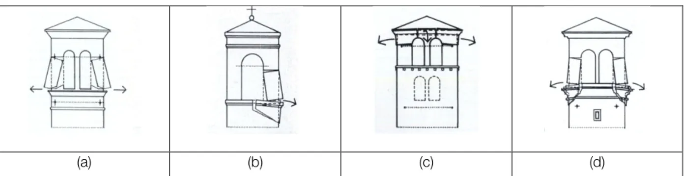
May 1976 and September 1976 (Doglioni et al., 1994). Mechanisms relating to 60 quadrangular towers have been considered. The damage analysis led to the consideration of two distinct macro-elements: the tower and belfry. The mechanisms related to the element tower have been linked to the division in two typology classes: the relation with adjacent buildings and the distribution of the openings on all four elevations. Six mechanisms are identified for the element tower: 1) out of plane rotation of the upper part of the tower due to actions out of plane (Figure 1a); 2) translation of the upper part of the tower, followed by the rotation of the entire tower; about the four sides of the tower two of them are failing in plane and two of them are failing out-of-plane (Figure 1b); 3) out-of-plane rotation in a hinge due of damages that create inclined cracks; 4) out-of-plane rotation of one or more inclined crack (Figure 1c); 5) rotation of the upper part of the tower resulting from the combination of two rotations around a vertical axis and a horizontal axis (Figure 1d); 6) translation of the upper part because of horizontal damage (Figure1e)
(a) (b) (c) (d) (e)
Figure 1 – Mechanisms for towers: a) kinematism 1; b) kinematism 2; c) kinematism 4; d) kinematism 5; e) kinematism 6 (Doglioni, 1994).
Mechanism 2 has been detected in a larger number of cases, particularly associated with isolated bell towers, which have no contact with other parts of the building. Mechanism 5 of rotation occurs also in a large number of cases, when the tower is connected with adjacent buildings.
For the macro-element formed by the belfry, three mechanisms have been identified: 1) translation or rotation-translation of the pillars (Figure 2a); 2) translation or rotation-translation of the pillars with shearing-off of the top rail (Figure 2b); 3) roto-translation out-of-plane of masonry at the base of the pillars (Figure 2c). It has been found that the damages could develop mainly at the ends of the pillars and at the middle of the beam. Moreover it has been observed that this type of damage and collapse is determined more by the characteristics of the masonry than the typology of the belfry.
(a) (b) (c) (d) Figure 2 – Mechanisms of bell towers considering the belfry: a) kinematism 1, b) kinematism 2, c) e d) kinematism 3 (Doglioni at al., 1994). The type of seismic damage in isolated towers was detected in the assessment of the damage caused by the earthquake of 1997 Umbria-Marche (Marchetti et al., 2004). The inspection has highlighted the formation of vertical cracks in correspondence of the openings, such as to divide the structure into parts corresponding to the corners of the tower. This mechanism is visible in the tower of Triponzo in Cerreto di Spoleto (Figure 3), which was partially collapsed during the earthquake of 1979. The subsequent intervention has been aimed to restore the missing parts and to build a curb on the top During the earthquake of 1997 rebuilt parts collapsed again in the same mechanism of damage.
Figure 3 – Seismic damages of isolated towers after the earthquake in 1997: a) different pattern of damage; b) example of Tiponzo Tower in Cerreto di Spoleto (Marchetti et al., 2004).
2.3
SAFETY ASSESSMENT METHODS
Investigations techniques are important to reach a good judgment about the conservation and the safety condition of the structure, considering the dead load, wind or seismic actions. To understand better an old building it is also necessary to adopt models that can replicate the behavior of the structure. There are different levels to verify the safety condition of a building suggest in the Italian Code (Linee Guida, 2010). A first level to evaluate the condition of the structure is the application of simplified models which depend on the typology of the structure. A second level is the analytic verification of the local mechanisms, again divided on their typology. Finally, a third level is the evaluation of the safety condition with mathematical advanced models.
2.3.1
SIMPLIFIED VERIFICATIONS
There are simple verifications that have been proposed (Binda et al., 1997) to find very easily dangerous situations in a structure, using only the principal dimensions and morphological characteristics. These calculations allow finding the stress at the base and the flexural failure, which can be compared with other cases. The work carried out in the Politecnico di Milano for towers (Binda et al., 1997) shows dangerous situations regarding the stresses at the base. The values have been obtained considering for brick masonry a specific weight of 18 kN/m3 and for stone masonry a specific weight of 20 kN/m3. The values for different towers have been compared with the average and maximum values on the section of the base of the Civic Tower of Pavia and of the bell tower of Duomo di Monza. The buckling has been calculated considering two limit conditions: the first one, optimistically, considers the masonry walls perfectly clamped and the entire section active; the second one, conservatively, considers the walls not clamped. The real buckling behavior will be between these two described limits. For this simple methodology of analysis, an elastic modulus of 2000 N/mm2 for the brick masonry and an elastic modulus of 4000 N/mm2 for stone masonry were used. These simple verifications are useful to indicate particularly unsafely cases.
About the seismic verification, the Italian Code “Linee Guida (2010)” indicates the need to verify the flexural failure, which considers the structure like a cantilever with the vertical dead load and a horizontal force of the earthquake. For rectangular hollow sections, which are the most common for towers, a formula to calculate the resistant bending moment Mu of the section has been proposed
!!= !!! ! ! − !!! !. !" ∙ ! ∙ !! (1) where:
a is the perpendicular side to the direction of the earthquake b is the parallel side to the direction of the earthquake A is the total area of the section
!! is the normal stress on the section, =W/A where W is the weight of the structure above the section !! is the compression strength of the masonry
The total applied bending moment is calculated considering a system of forces distributed along the height of the structure.
2.3.2
ANALYTICAL VERIFICATIONS
In the last years several earthquakes caused strong damages in historical constructions. The inspection of the collapses has allowed identifying specific damage mechanisms in towers and bell-towers, as discussed above. The safety verification method with limit analysis of the equilibrium needs the
identification of the kinematisms that the structure can develop. Each structure is a single case and the mechanisms of the “Linee Guida, 2010” (Italian Code) to be applied require experience and a critical review.
Figure 4 – Collapse mechanisms for bell towers (Linee Guida, 2010): a) tower, b) belfry, c) roof
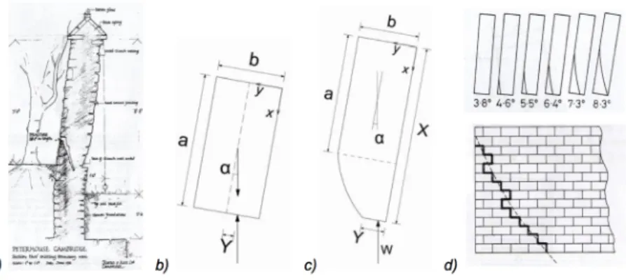
In the verification of the stability the masonry the material is considered without tensile strength and with infinite compression strength (Heyman, 1992). These considerations have been made during the inspection of the damages on medieval tower in Cambridge, with diagonal inclination on the parallel sides of the slope (Figure 5a). By a mathematical analysis it has been possible to describe the crack pattern and to calculate the limit slope for the stability of the construction. Considering a parallelepiped with height a and base b, inclined with an angle
α
(Figure 5b), the results are that in uplifting part the stress is ! = !. The value ofα
to reach this condition is:!"#$ =! !∙
!
! (2)
Considering now a parallelepiped with generic inclination (Figure 5c), it is possible to calculate a from the previous equation: the distance from top such that at the left corner there is zero stress. In each section in a generic distance X from the top it is possible to consider the reduced section Y, where the reaction force will be applied at 1/3 of Y.
Figure 5 – Leaning towers: a) Medieval Tower of Peterhouse, Cambridge; b) inclined parallelepiped; c) parallelepiped with generic inclination; d) crack development (Heyman, 1992).
From the results of the equilibrium equations in the kinematism of the small part with height dX it is possible to obtain the parametric equations that described the curve ! = ! (the line of the crack in the masonry) that are expressed in the variables x=X/a, y=Y/b (Figure 5d).
! = ! + ! ∙ !!! !"#!
!− !"# ! (3)
! = !!!∙ !! ∙ !!!! (4)
The ultimate inclination is reached when the crack line passes through all the depth of the tower, which is the condition y=0 and provides:
!"#$ = !. !"#"! !
(5)
where H is the full height of the tower. This solution is valid for full sections, while usually real cases are characterized by hollow sections. For these hollow sections there is an approximate solution where the crack line is considered linear and the section thin: b=c, where b is the external dimension of the base and c the internal dimension. The approximate solution provides the maximum angle of inclination:
! = !"(!/!) (6)
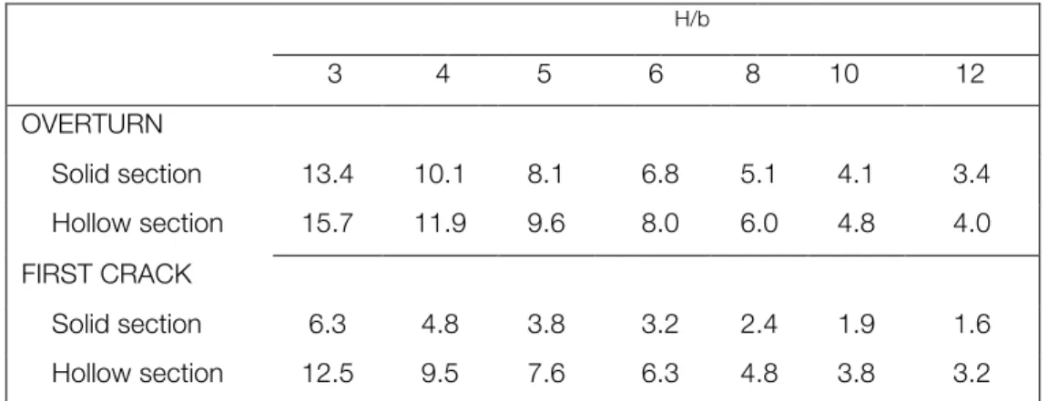
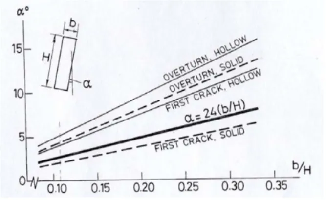
Comparing the angles of maximum inclination it is possible to observe that, with the same dimensions, the approximate solution for full section provides a critical angle lower than the one for hollow sections (Refer as Table 1). The angle when the first crack appears at the base of the tower has been calculated also: !"#!!(!
!∙ !
!) for the full section; !"# !!(!
!∙ !
!) for the hollow section. The angle of inclination that corresponds at 24(b/H) is the ultimate safety value; beyond this value stability is no longer ensured.
H/b 3 4 5 6 8 10 12 OVERTURN Solid section 13.4 10.1 8.1 6.8 5.1 4.1 3.4 Hollow section 15.7 11.9 9.6 8.0 6.0 4.8 4.0 FIRST CRACK Solid section 6.3 4.8 3.8 3.2 2.4 1.9 1.6 Hollow section 12.5 9.5 7.6 6.3 4.8 3.8 3.2
Figure 6 – Leaning towers: critical angle of inclination for different values of the ratio base/height (Heyman. 1992).
The solution that has been found is valid for inclinations parallel to one of the sides of the rectangular section. For instance to evaluate the safety condition of the bell tower of San Benedetto in Ferrara the analytical formulation has been generalized, for any inclination of the axis of the tower with respect to the vertical axis and the axes parallel to the section of the base (Laudiero et al., 2003).
2.3.3
MATHEMATICAL ADVANCED MODELS
Mathematical models of a structure could be developed using different methods considering the aim of the analysis and the level of knowledge of a building and its characteristics. The computational burden of data processing is currently easy thanks the use of computers; for this reason today the finite element method using 2D and 3D elements is very used. In the specific case of the towers the simplicity of the structure allows to create models that replicate well their thickness and the materials present without using too many elements. Masonry has a non-linear behavior in tension and compression and is also anisotropic. However, in many cases, a linear isotropic model is used for the material, due to the computational efforts required by non-linear material models, because is not easy to know the properties of a historical masonry in detail and also because many users do not have sufficient skills to adequately used non-linear analysis.
The dimension of the height of a tower is bigger that other dimensions, this allows also to use 1D models (Cerioni at al., 1996; Riva et al., 1998). One possibility is to decompose the structure in beam elements with linear-elastic behavior and to concentrate the non-linearity in the nodes. For instance the model of the Tower of Asinelli in Bologna (Riva et al., 1998) is made with beam elements with elastic behavior (E=5000 N/mm2; ρ=1800 kg/m3) linked with truss elements in the nodes. The truss elements have deformability only along their axis and different values of ultimate tensile and compressive strength. Also in the frame of 3D models, 1D elements have been used (Aoki et al., 2006; Ceravolo et al., 1999). These types of models have the advantage to show a clear interpretation of the dynamic behavior of the tower using a very simple model. The FEM method can be used for 2D models that represent a façade of
a building (Bartoli et al., 2006; Cerioni et al., 1996; Thomas et al. 1996; Valluzzi et al., 2006). These models have been used to evaluate the in plane behavior of the masonry under different load conditions. Still, the most used method for towers seems to be FEM 3D with solid volume elements “brick” (for instance: Abruzzese et al., 2005; Barsotti et al., 2007; Balduzzi et al., 2006; Benedetti et al., 2007; Carpinteri et al., 2005; Cerioni et al., 1996; D’Ambrisi et al., 2004; Gentile et al., 2007; Ivorra et al., 2006; Lionello et al., 2005; Pavese et al., 1995; Rebelo et al., 2007; Rossi et al., 1992). These models allow a good geometry representation and the identification of the materials. In some cases, the models show also the soil, with the goal of understanding the interaction between the ground and the foundations of the structure (Abruzzese et al., 2005; Beconcini et al., 2006). If there are other buildings near the tower, it is possible to make the constraints modeling these parts of the structure (Decanini et al., 1997; Lionello et al., 2005). At the beginning of the modeling it is possible to assign the characteristics of the materials. It is also necessary to assign many parameters, in particular for the non-linear and anisotropic behavior, that often are not easy to interpret. Another strategy for towers modeling is the utilization of 3D FE models with shell elements (Reale et al., 2001; Ramos et al., 2007) that have the advantage to be a lower burden from a computational point of view.
The numerical models can be used to verify the safety of the structure under an assigned load, but also to interpret the results of experimental tests and dynamic tests. The most common analyses are linked with the dead load, wind action and seismic action. Two verifications are particularly relevant: the inclination of the axis of the tower and its increase (Carpinteri et al., 2005); the non-linear time dependent behavior in compression, which is defined as creep (Papa et al., 2001). The safety verification of the wind action is usually made considering this action like a pressure statically applied (Carpinteri et al., 2005; Modena et al., 2002; Rossi et al., 1992; Valluzzi et al., 2003), neglecting possible dynamic effects. Further safety verification of the structure is made implementing the stresses of the thermal changes (Modena at al., 2002) that in the case of towers can be considerable.
The seismic verification is made using 4 methods: linear static analysis, non-linear analysis, dynamic linear analysis and dynamic linear analysis. From the code in Italy, “Linee Guida (2010)”, the static non-linear verification needs the application of two forces: one proportional to the weight and one proportional to the first vibration mode. In the case of towers and bell towers, it is interesting to consider the distribution of the forces proportional to the vibrations modes higher than the first one (Ceroni et al., 2007). The dynamic analysis provides the application of a time history to the finite elements model where in non-linear analysis the materials have non-linear characteristics (Abruzzese et al., 2004; Azorin et al., 2006; Ivorra et al., 2006). This makes this analysis particularly burden from the computational point of view; that is why is easier using simplified models also for the towers (Cerioni et al., 1996; Riva et al., 1998).
2.4
REPAIRING AND STRENGTHENING TECHNIQUES
From the identification of the structural specific problems it is possible to choose the intervention for repairing and strengthening. Each strengthening techniques is designed for a single damage or multiple damages.
Towers are often subjected to settlements of the soil under the foundations. In the past deep underpinning with micropiles has been used with the aim of rigidly securing the structure to the substrates of the soil that have better mechanical characteristics (Mastrodicasa, 1993). Today the intervention techniques, that could be less invasive, can interest the substructure and the foundations. For instance the strengthening operation of the bell tower Santa Maria Gloriosa dei Frari in Venice (Lionello, 2008) where the soil fracturing technique was used, consisting of high pressure injection of cement mortar to increase the mechanical characteristics of the clay soil foundations.
Regarding the structure there are two common techniques used to strength masonry and towers: injection of lime based grouts (Ceravolo et al., 1999; Modena et al., 2002; Valluzzi et al., 2005) and the reparation with the “scuci-cuci” technique (local repairs by reconstruction) of the most damaged parts (Indirli, 2000; Modena et al., 2002; Valluzzi et al., 2005; Vegas Lopez-Manzanares et al., 2005).
2.4.1
TIE RODS
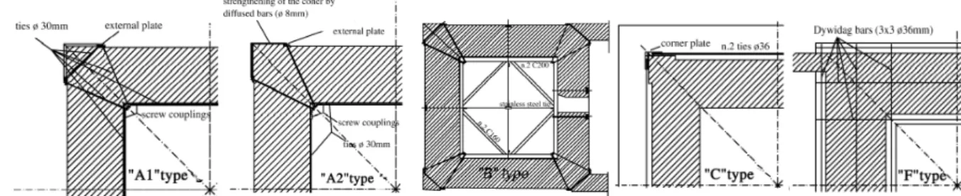
Another traditional strengthening technique is the utilization of steel tie rods. This technique improves the connection between the walls and also increases the confinement of the masonry. In slender structures like towers the connection between adjacent walls is very important, as there are usually damages in the corners that induce a non-box behavior of the construction. This technique has been used in many interventions, for instance the bell tower of the Cathedral of Avellino (Mastrodicasa, 1993), tower of Fraccaro in Pavia (Ballio, 1993), the bell tower of Maria SS. Annunziata in Roccaverano (Ceravolo et al., 1999). The tie rods have been placed in different levels of the structure in order to confine the walls. For instance an interesting case is the intervention with a series of stainless steel reinforcing rings that have been planned to be applied in different horizontal sections of the Monza Cathedral bell-tower (Modena et al., 2002). These reinforcing rings have been properly designed depending on the particular local conditions detected on the structure. There are different types such as “A” types are composed by two internal rods (30 mm in diameter) anchored to stainless steel plates which will be possibly included in proper recesses successively closed by masonry. This is complemented by the general solution for the anchoring of the ties, the “A2” type, characterized by the local strengthening of the masonry by means of a series of steel bars diffused along the connection zone. The vicinity of the church at the first level led to the “A1” type solutions, performed by the transversal connection of the anchoring ties. Because of the presence of a vault at the height of 11 m from the bell-tower a C-shape metallic components and tie
rods, types “B”, anchored by plates not visible from outside were also applied. The only reinforcing ring external to the structure, type “C”, has been placed at the cornice level composed by two tie rods (36 mm in diameter). It has been decided also to apply a further reinforcing ring at the foundation level, type “F”, executed by four reinforced concrete beams connected by a series of post-tensioned bars inserted in cored holes.
Figure 7 – Different types of reinforcing rings in the bell-tower of Duomo di Monza: a) A1 type; b) A2 type; c) B type; d) C type; e) F type Another interesting case is the strengthening intervention of the Civic Tower of Vicenza (Valluzzi et al., 2003). Also in this case the stainless steel reinforcing rings designed have been of three different kinds. Type “A” has been used to reinforce the octagonal tip of the tower. Type “B” and “C” have been used along the height of the tower, at seven different levels. All the reinforcing rings have been specifically designed on the basis of the particular conditions and geometry of the structure. The original design with an anchoring plate have been abandoned and substituted with a stainless steel cross in order to reproduce the historical element found on a pillar of the belfry (Figure 8a and b). Type “C” has been placed at the base of the tower, composed by two rods for each wall (Figure 8c). Moreover, small diameter (6 mm) stainless steel reinforced bars were placed in the mortar joints at the same height of the reinforcing rings, in order to assure a confining action at the corners of the walls.
Figure 8 – Reinforcing rings in the Civic Tower of Vicenza: a) external view; b) scheme; c) new anchor element and scheme of the “C” type of reinforcing ring.
In both the interventions of the bell-tower of Duomo di Monza and of the Civic Tower of Vicenza reinforced repointing has been used, in the part affected by high compression. This technique is based on the insertion of small diameter reinforced bars (stainless steel or FRP bars or plates) into the joint previously excavated and then repointed by mortars having generally better characteristics than the original ones (Modena et al., 2002; Valluzzi et al., 2005). This method can be adopted in case of towers subjected to sustained heavy loads.
2.4.2
BASE ISOLATION
The safety verification of the seismic action is often not satisfied in historical buildings and high seismic hazard zones. Seismic isolation is ensured using devices that give to the bearing system a large vertical stiffness and a low horizontal stiffness, which absorbs and reduces significantly the accelerations imposed by the earthquake. The isolated structure translates as a rigid body on the seismic isolation system, where all the deformations are concentrated. The periods increase and the structure leaves the area of the response spectrum with greater accelerations, while the displacements between floors are reduced. There are 3 families of devices: 1) Isolation: disconnection of the structure from the foundations, so that the seismic action transmitted by the ground does not reach the building. This device is equivalent to increasing the fundamental period of the structure. 2) Energy dissipation: limitation of the accelerations transmitted to the structure, by reducing the inertial forces. These devices absorb a part of the energy that acts on the structure. 3) Connection: in order to prevent or limit the displacements of the building with respect to the bearings, or in order to equally distribute the dynamic forces.
2.4.3
OTHER TECHNIQUES
It is clear that the seismic devices do not have to increase the stresses in the structure. The intervention can affect the all structure only where it is more vulnerable. A technique of seismic isolation can be made with an independent metal structure inserted inside the tower and linked to the walls (Barteletti et al., 1992; Balduzzi et al., 2006). For instance in the intervention in the bell-tower of Santa Lucia in Serra San Quirico in Ancona (Cosenza et al., 2007), an innovative material like FRP (Fiber Reinforced Polymers) was used to create a reticular system with vertical, horizontal and diagonal bands of FRP in the internal masonry of the tower (Figure 9a). These bands are 0.336 mm thick and 20 cm large.
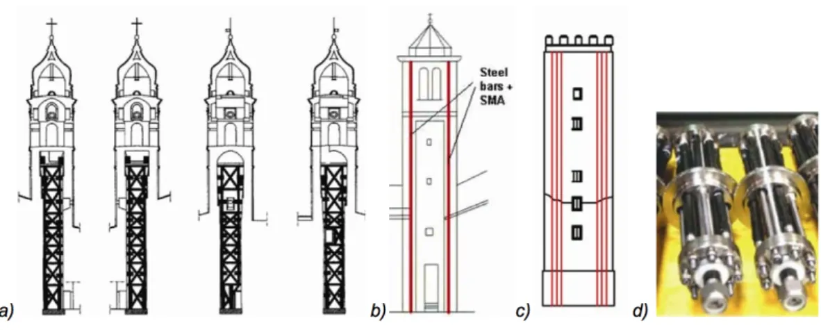
Figure 9 – Seismic strengthening: a) reticular System with FRP, bell-tower of S. Lucia (Cosenza et al., 2007); b) devices SMAD, bell-tower of S. Giorgio (Indirli, 2000); c) devices SMAD, Capocci Tower (Abruzzese et al., 2004); devices SMAD (Abruzzese et al., 2004).
Other innovative technique consists of SMAD (Shape Memory Alloy Device). During the research project ISTECH “Development of Innovative Techniques for the Improvements of Stability of Cultural Heritage, in particular Seismic Protection” the applicability of the SMAD devices has been verified. This project has been concluded in 1999 and it included the restoration of the bell-tower of San Giorgio in Trignano, close to Reggio Emilia, that was significantly damaged after the earthquake of 1996 (Indirli, 2000). In the repairing intervention steel pre-tensioned bars positioned vertically in the four corners of the bell-tower have been inserted (Figure 9b). Each tie rod is made with two segments divided by a SMAD device, which is at the third level of the structure. The same technique has been used in the seismic improvement of the Tower of Capocci in Rome (Abruzzese et al., 2004). To increase the assessment of the structure with the foundation and to increase the vertical tensile strength five tie rods at each internal corner have been inserted, with a SMAD device (Figure 9c).
3. LAMBERTI TOWER
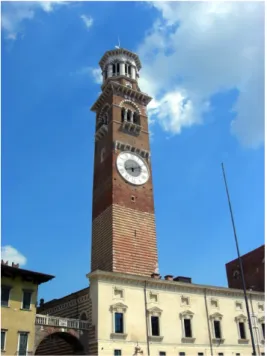
The Lamberti Tower is a medieval tower high 84 m in Verona, northern Italy. This historical construction is located in the center of Verona, in “Piazza Erbe”, and is the symbol of the city’s municipal power. This tower, even if it has bells, is not a bell-tower, because it does not have any religious meaning: it is only the demonstration of the municipal power of the city.Figure 10 – Lamberti Tower, picture from the square “Piazza Erbe”
In Italy, particularly in the medieval age, many towers appeared in the most important and powerful cities. The ancient builders tried to challenge the structural stability and the nature itself realizing towers, as a need of cities or families to show their power.
Fortunately the Lamberti Tower did not have particular damages in the course of the years. The tower is almost intact and in the last centuries only a few interventions have been carried out. The construction begun in 1172 and it is divided in two different phases. The first part of the tower, made with alternating layers of tufa and brick, has been done at the end of the 12th century and it corresponds more or less with the original tower. In May 1403 a lightning bolt struck the top of the tower, but only in 1448
restoration works were started and they continued until 1464. In this occasion the tower was enlarged: the more recent sections can be recognized today by the use of different materials. So the upper part has been built between 1448 and 1464. The large clock was added in 1779. The tower has been built with different materials: marble, bricks, tuff and stone. In the first part there is a combination of tuff and bricks, the second one only in bricks and finally only marble. In the first belfry there are “trifore” with columns and small stone balconies. Above there is the octagonal stone belfry with “bifore” and a stone perimeter frame. The roof is realized with eight inclined surfaces and there is a timber frame that supports lead plates. The tower is the highest of the city and reaches 79,10 m at the top of the roof and 83 m with the weathervane surmounting the sphere.
Figure 11 – Front and back of Lamberti Tower
3.1
GEOMETRY
The tower has depth of the foundations that is 5,20 m below the ground level. The plan dimensions are of 9.10 x 8.75 m (at the level of the courtyard of “Mercato Vecchio”) with thick walls of 2.30 m. The dimensions are gradually tapering going on the top of the tower. The plan dimensions become 8.70 x 8.50 m with a thickness of the wall of 1.80 m (at the level of 59 m from the ground). The first belfry has an octagonal base and is at 53.43 m, the second belfry is at 68.23 m and is supported by the previous one with a domed vault. The covering is at 77 m and has a pyramidal shape and octagonal base. Three openings adorn the top of the tower: monofore at the level of the clock, trifore at the level of the first belfry with stone columns and cantilevers which form four balconies, and bifore at the level of the second belfry with only one stone column in the center.
Figure 12 – Section of Lamberti Tower at the level of the courtyard “mercato vecchio” and on the right section of the top of the tower
3.2
CHARACTERISTICS OF THE SOIL
In December 2005 a soil survey by “TECNOBREVETTI s.r.l.” has been made. The result of the stratigraphy (made in the southeast corner of the tower considering the Geotecnica Veneta) has been: from 0.00 to -0.50 m flooring material; from -0.50 to -1.20 m fine gravel, from -1.20 to -1.90 m fragments of limestone with remains of bricks; from -1.90 to -3.50 m fine gravel with traces of clay and pebbles of porphyry; from -3.50 to -4.00 slightly silty sand with coarse gravel and pebbles of porphyry.
Figure 13 – Samples of the soil survey of Lamberti Tower
Results from other soil surveys carried out close to the Lamberti Tower have a very similar stratigraphy and show that the coarse gravel extends up to a depth of -15 m. Because the gravel has a very high load–bearing capacity it can be established that the soil and the foundations perform very well their static–dynamic task.
3.3
CHARACTERISTICS OF THE MATERIALS
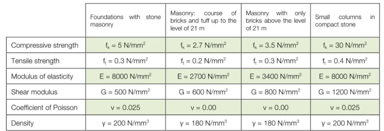
The Lamberti Tower is a masonry tower divided in two main parts: until the level of 21 m it is made with courses of bricks and tuff and above the level of 21 m the masonry is composed of bricks. The small columns, which are possible to see in the belfry, are in compact stone and the covering is composed with timber. The foundations are made with stone masonry.
Foundations with stone masonry
Masonry: course of bricks and tuff up to the level of 21 m
Masonry with only bricks above the level of 21 m Small columns in compact stone Compressive strength fk = 5 N/mm2 fk = 2.7 N/mm2 fk = 3.5 N/mm2 fk = 30 N/mm2 Tensile strength ft = 0.3 N/mm2 ft = 0.2 N/mm2 ft = 0.3 N/mm2 ft = 0.4 N/mm2 Modulus of elasticity E = 8000 N/mm2 E = 2700 N/mm2 E = 3400 N/mm2 E = 8000 N/mm2 Shear modulus G = 500 N/mm2 G = 600 N/mm2 G = 800 N/mm2 G = 1200 N/mm2 Coefficient of Poisson ν = 0.025 ν = 0.00 ν = 0.00 ν = 0.025 Density γ = 200 N/mm3 γ = 180 N/mm3 γ = 180 N/mm3 γ = 200 N/mm3
Table 2 – Characteristics of the material that compose the Lamberti Tower
3.4
DESCRIPTION OF THE BELLS
The bells of the tower are also a symbol of the city of Verona. The first bells were placed around 1272-1276 and over the years have been redone and replaced many times. The main bells are called “Rengo” and “Marangona”, being the first one bigger and being located above the other one. The sound of the bell “Rengo” had the principal aim to convene the city parliament called “Arengo”: it is from this word that derives the name “Rengo” of the bell. The goal of the bell “Marangona” was to indicate the beginning and the end of the work activities. The two bells have been rebuilt in 1311 for the important family of Verona “Gli Scaligeri” and after that there have been other restorations and recasting interventions.
The bell called “Rengo” is positioned on the top of the tower and has bigger dimensions when compared with all the others. This bell has a weight of 4215 kg, a diameter of 1831 mm and its direction of oscillation is North–South. It is the second biggest bell in the Italian region Veneto. The present bell has been placed in 1798, the same year that in the tower was inserted a clock. Today, the bell is used during major city events.
Figure 15 – Plant of the belfry and picture of the bell called “Rengo”
The bell called “Marangona” is positioned below the other bell “Rengo”. Two other smaller bells, called “Rabbiosa” and “SS. Fermo e Rustico”, flank it. The four bells together create a harmonious musical chord that was very famous in the music of the past. The frame of the belfry is in steel, with cast iron counterweights; unlike the frame “Rengo” this one does not have posts and the supporting beams are inserted directly into the walls where they are fixed with cement mortar. The bell “Marangona” has a weight of 1300 kg and a diameter of 1298 mm, the bell “Rabbiosa” has a weight of 750 kg and a diameter of 1080 mm and finally the bell “SS. Fermo and Rustico” has a weight of 330 kg and a diameter of 610 mm. All these bells have a direction of oscillation that is East – West.
3.5
PREVIOUS DYNAMIC ANALYSIS RESULTS AND INSPECTIONS
The office “4-EMME SERVICE S.p.a.” carried out preliminary analyses on the Lamberti Tower. The aim of their project has been the verification of the safety conditions of the tower under excitation of the bells. A Dynamic Analysis was made and with the appropriate tools the natural frequency of the tower has been obtained by exciting the structure with a few tolls of the two biggest bells. The induced vibration has been obtained by the movement of the bell called “Rengo” in direction north – south and the bell “Marangona” in direction east – west.
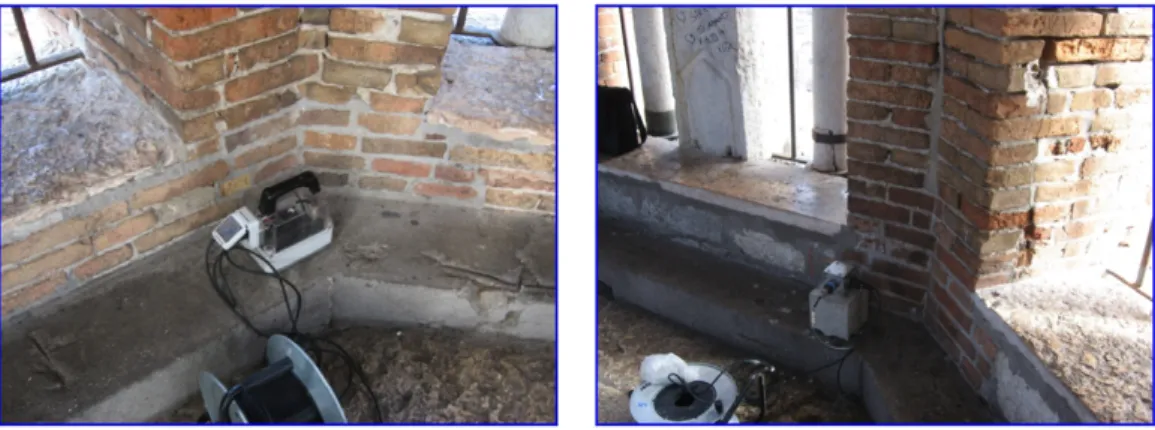
Figure 17 – Accelerometers positioned in the N-W and S-E corners of the belfry “Rengo”
For the determination of the natural frequency of the structure it has been used three pair accelerometers. The sensors were placed respectively in the north-west and south-east corner (on the opposite sides of the octagonal belfry of the "Rengo”) on the reinforced concrete frame which is 68.50 m from ground level. The second backhoe of accelerometers was placed on the balcony of a small opening, at east more or less in the middle of the tower (33.50 m from ground level). The sensors have been placed in the position shown by Figure 18.