Concrete structures. Contribution to the safety
assessment of existing structures
Estruturas de concreto. Contribuição à análise
da segurança em estruturas existentes
a Universidade Estadual de Campinas; PhD Engenharia; b PhD Engenharia.
c Professor Titular da Universidade de São Paulo; PhD Engenharia.
Received: 17 Oct 2014 • Accepted: 20 Mar 2015 • Available Online: 12 Jun 2015
Abstract
Resumo
The safety evaluation of an existing concrete structure differs from the design of new structures. The partial safety factors for actions and resis-tances adopted in the design phase consider uncertainties and inaccuracies related to the building processes of structures, variability of materials
strength and numerical approximations of the calculation and design processes. However, when analyzing a inished structure, a large number of unknown factors during the design stage are already deined and can be measured, which justiies a change in the increasing factors of the ac -tions or reduction factors of resistances. Therefore, it is understood that safety assessment in existing structures is more complex than introducing security when designing a new structure, because it requires inspection, testing, analysis and careful diagnose. Strong knowledge and security concepts in structural engineering are needed, as well as knowledge about the materials of construction employed, in order to identify, control and properly consider the variability of actions and resistances in the structure. With the intention of discussing this topic considered complex and dif-fuse, this paper presents an introduction to the safety of concrete structures, a synthesis of the recommended procedures by Brazilian standards and another codes, associated with the topic, as well a realistic example of the safety assessment of an existing structure.
Keywords: structures safety, existing concrete structures safety, concrete structures evaluation.
A avaliação da segurança de uma estrutura de concreto existente difere daquela adotada no projeto de estruturas novas. Os coeicientes de ponderação das solicitações e das resistências, adotados na fase de projeto, levam em conta incertezas e imprecisões relacionadas com os
processos de construção das estruturas, variabilidade da resistência dos materiais, além das aproximações numéricas dos processos de cálculo e dimensionamento. Entretanto, quando se analisa uma estrutura acabada, um grande número de fatores desconhecidos durante a etapa de
projeto já se encontram deinidos e podem ser mensurados, o que justiica uma redução nos coeicientes de majoração das ações ou de mino -ração das resistências.
Diante disso, entende-se que analisar a segurança de uma estrutura acabada é muito mais complexo que introduzir a segurança no projeto de
uma estrutura nova, pois requer inspeção preliminar, ensaios, análises e vistoria criteriosa. São necessários sólidos conhecimentos e conceitos
de segurança em engenharia estrutural e também conhecimentos sobre os materiais de construção empregados, de forma a identiicar, controlar
e considerar corretamente a variabilidade das ações e das resistências na estrutura. Com a intenção de discutir este tema considerado complexo
e difuso, apresenta-se neste artigo uma introdução à segurança das estruturas de concreto, uma síntese da revisão bibliográica dos procedi -mentos recomendados por normas nacionais e normas internacionais associadas ao tema, bem como um exemplo prático de avaliação de uma
estrutura existente para veriicação da segurança.
Palavras-chave: segurança de estruturas, segurança de estruturas existentes, avaliação de estruturas de concreto.
D. COUTO a
[email protected] M. CARVALHO b
[email protected] A. CINTRA b
[email protected] P. HELENE c
1. Introduction
Due to recent events related to the collapse of structures in Brazil1 and the world2, the attention of the technical community to struc-tural safety issues grows increasingly. There are several cases of buildings that are breaking down even before handed over to the customer, that is, during the construction period. In addition, there
is a growing market for retroit of existing structures, which makes
this current and of great practical interest matter, for a large part of structural engineers do not mastered the concepts, models and safety criteria of assessment of an existing structure.
Although they are subject to depreciation over time, being exposed to
the environment and also the use, and even if they have or not prop-erly maintained, as required by the ABNT NBR 5674:2012 [1], is
un-workable and unacceptable, economic and environmentally, that the buildings are simply replaced when they reach the end of their design life (VUP), provided in accordance with ABNT NBR 15575:2013 [2]. It is also unacceptable that existing structures are analyzed ac-cording procedures applicable only in new structures, often result-ing in unnecessary interventions and strengthenresult-ing, which could make unfeasible the business by term and/or excessive costs,
cre-ated by a mistaked project.
Therefore, given the complexity of the study and analysis of exist-ing structures, the evidence of the frequency of partial or total col-lapse of structures in use or under construction3, and considering that Brazil has an immense amount of buildings with advanced age, with incalculable heritage built in concrete, the discussion about the security of these structures is even more necessary and urgent.
1 Torre de moinho desaba e deixa 5 feridos em Maceió; moradores são retirados. Describes the collapse of a structure of 50 years of age, even after reforms increased weight together had no structural reinforcement. The accident left injured and damaged homes. Available in:http://g1.globo.com/al/alagoas/noticia/2014/09/moinho-que-desabou-em-maceio-tinha-problemas-estruturais-diz-laudo.html. Access: October, 08th 2014.
2 Once investigaciones por caso Space precluyeron: Fiscal. Describes unfortunate tower collapse case in Colombia, followed by demolition and implosion of similar towers by serious mistake project. Available in: http://www.vanguardia.com/actualidad/colombia/279832-once-investigaciones-por-caso-space-precluyeron-iscal. Acess: October, 01st 2014.
3 As an example, we can mention the signiicant recent collapses: Building Sand White (Pernambuco, 2004. Building with 25 years, delivered in 1979, collapsed completely due to execution failed connections shoes and pillars), Royal Building Class (Pará , 2011. collapsed under construction due to errors in design and construction), building Freedom (Rio de Janeiro, 2012. He collapsed, taking with him two adjacent buildings, and revealed errors in the reform of procedures), Shopping Rio Poty (Piauí, 2013. building under construction that collapsed due to failure to execute related to shoring).
Table 1 – Motives, scopes and actions that justify safety assessment of existing structures (Helene [3])
Motives Scope Actions
Concrete receipt control, in new work site,
points that fck,est < fck
Search for the new fck, to redesign or assessment of
structural safety
Transform concrete compressive strength results obtained by drilled cores in values that are equivalent to concrete characteristic strength
of the new structure, in order to allow the use of the same safety methods adopted for design of new structures.
Concrete looking improper or not complying with the
ordered/specified
Analyze concrete for comparison with orders/
specifications
Search for composition, mix design, specified strength and other prop-erties of the delivered concrete for casting of a structural element, as ordered for the concrete supplier. Usually, these are commercial issues
between the companies.
Concrete exposed to aggressive environment
Analyze concrete characteristics e properties related to
its resistance to the aggressive environment
Complex concrete life cycle analysis in that environment based on the design service life of the structure, preventive maintenance prescriptions of the structure use and maintenance manual, eventual
accelerated tests or assessment of similar existing buildings. With the concrete compressive strength, characteristics and properties, apply
service life models available in the technical literature.
Quality of structure execution
Analyze concrete homogeneity, dimensions
of casted elements, tolerances
Analysis aided by use of semi destructive and nondestructive tests, topography resources, level and laser plummet, columns eccentricity, geometrical dimensions and drilled cores sampling of complementary
areas, intended to the quality assurance of concreting services complying with codes requirements.
Survey Inspection and diagnosis to clarify pathologic issues
Application of recognized and sophisticated techniques for field inspections and lab and field tests, eventual load tests, drilled cores
sampling, intended to the diagnosis and prognosis of partial or full collapses, a severe repair issues and severe deformations.
Change of use, retrofit Assess the conditions of the existing structure
As built structural analysis with inspection of dimension, reinforcement, concrete, drilled core sampling, etc., intended to the safe change of
use of the structure, with no increase of overloads.
Corrective intervention or structural rehabilitation
Assess the present safety conditions and design necessary interventions
Application of recognized and sophisticated techniques for field inspections and lab and field tests, eventual load tests, drilled cores
There are several reasons that can lead to the need of assessing an existing structure safety, leading to different scopes of work, set out in Table 1.
The safety assessment of an existing concrete structure is dif-ferent from that adopted for a new one [4]. According to stan-dard ABNT NBR 8681:2003 [5] and ABNT NBR 6118:2014 [6], the partial factors for actions and strength, adopted in the design phase, take into account uncertainties and inaccuracies related to the construction processes of structures, variability of materials strength, in addition to numerical approximations of calculation and design processes.
However, when analyzing a inished structure, a large number
of these unknowns factors during the design phase, are already
deined and can be measured, which justiies a modiication in
actions increasing factors and in strength reduction factors [7]. This issue was already addressed in 1983 by the Committee Eu-ro-International du Beton (CEB). Regarding to actions, the CEB [8] already indicated that, at least for the sustained loadings, the increasing factors adopted for existing structures analysis should be lower than usual, based on geometric measurements, actual densities and more accurate load estimations.
With regard to materials, the CEB also warned about the val-ues of “characteristic” compressive strength of concrete, to be
considered in the analysis of existing structures. By deinition, a
characteristic value is linked to a concept of security and quality of the structures before construction, which makes this aplica-tion inconsistent for existing structures, in which geometries and properties of used materials are better known.
In addition, it was also mentioned the need of considering a sec-ond problem: the age at which the characteristic value should be referenced, since most of the design codes was based on nomi-nal strength values at 28 days (as to this day). As in that time, today the study of structures age conversion for 28 days is still little used, controversial and uncertain.
Therefore, it is understood that analyze the security of a inished
structure is much more complex to enter the safety of a new structure design, it requires preliminary inspection, testing and careful survey. It takes solid security knowledge and concepts in structural engineering as well as knowledge of the construction
materials used in order to identify, control and properly consider the variability of actions and strength in the structure.
In order to discuss this topic considered complex and diffuse, is presented in this paper an introduction to the safety of concrete structures, a synthesis of the literature review of the procedures recommended by Brazilian regulations and international stan-dards established and respected in Brazil associated with the topic as well as an assessment of the implementation of the hypothetical example of an existing structure for security
veri-ication.
2. Safety in design of concrete
structures
The concept of security structures, in general, is associated with statistical tools and is characterized by probabilistic analysis of a structure to maintain its bearing capacity, preventing their ruin
[9]. This way are deined limits states (ultimate or service) to the
structure and, regardless of the method of calculation used, the
project should be performed in order to always maintain the rela -tionship Rd ≥ Sd 4.
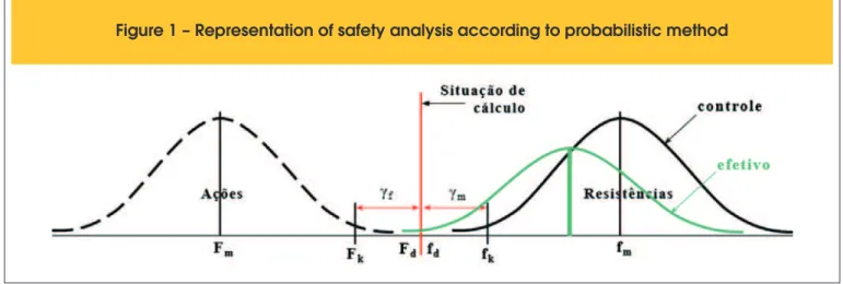
Fig.1 shows a simpliied view of probabilistic safety consideration. Through the of semi-probabilistic analysis of variables inluencing
the safety of structures, namely increase actions and reduce ma-terial strength, it is possible to perform the design of new struc-tures and assess the security of existing strucstruc-tures, this time with
effectively measured or ield estimated values.
To this end, the ib Model Code 2010 [10] recommends four safety model checking, of whom an cites two: Security Probabi-listic Method and Partial Safety Factor Method (or Semi proba-bilistic method).
n Probabilistic Method: because of its complexity and even lack
of knowledge of the variables, it is not the most used and
therefore will not be subject of discussion in this article;
n Partial Safety Factor Method: also known as
semi-probabi-listic method makes use of predetermined conversion
coef-icients for calculating characteristic values of values.
The ABNT NBR 8681:2003 [5] offers stress calculating tools based on this method, as the following concepts:
4 Design Strengths (Rd) must be greater than Design Actions values (Sd).
For actions:
(1)
F
d= F
k·
g
f(2)
g
f
=
g
f1
·
g
f2
·
g
f3
gf1 : considers variability of actions;
gf2 : combination coeficient (ψ0 - simultaneity);
gf3 : considers possible assessment errors of the actions effects due to construction method or calculation method.
For materials strength:
(3)
fd
= fk
/
g
m
(4)
g
m
=
g
m1 ·
g
m2 ·
g
m3
gm : can refer to concrete (in this case, is called gc) and to steel (gs).
gc1: takes into account the variability of the effective strength of the concrete structure, which is always greater than the vari-ability of resistance “potential” of the concrete in their production
source, as evaluated by molded specimens;
gc2: considers the differences between the effective resistance of the concrete in the structure and the potential resistance
mea-sured in conventionally standardized specimens;
gc3: considers the uncertainties in the determination of resistant requests, whether as a result of the construction methods, wheth-er as a result of the method (model) of employee calculation.
Cremonini [11] explains that the coeficients gc1 and gc2 can be determined by experimental measurements and statistical ana-lyzes as gc3 is found by means of empirical criteria. In the case
of concrete, it can be considered that decomposes gc approxi-mately the following parts:
(5)
g
c
=1,07 a 1,32 (
g
c1
)
· 1,10 (
g
c2
)
· 1,10 (
g
c3
)
The result of the product of the plots varies between 1.30 and 1.60. Table 2 shows the comparative values adopted by Brazilian
stan-dards compared to the requirements of ib Model Code 2010 [10].
Some researchers believe, mistakenly, that aspects related to the strength and variability of the constituents of concrete materials are covered by gc, but it is clear that, conceptually, this coeficient exclusively covers the differences between the concrete strength control procedures, well established in ABNT NBR 5738:2003 [13] and in ABNT NBR 5739:2007 [14], and the procedures adopted in construction site [15].
Therefore, the coeficients gc1 and gc1 (product of order 1.3 to 1.45), as stated by the ABNT NBR 8681:2003 [5], cover the unknown dif-ferences between the geometry of the standard specimen and the structural component geometry as well as their actual characteris-tics of density, launch, healing, shoring removal and early loading, which in general are different from standard procedures in ABNT NBR 5738:2003 [13].
It is evident that the work procedures are unlikely to be as accurate as the control prescribed by ABNT NBR 12655:2006 [16], such that the effective resistance of the concrete compression in the structure will always be less (of 1.3 or order less) that resistance of the con-crete compressive assessed by ABNT NBR 12655:2015 [16]. An experimental approach to gc coeficient can be obtained through actual comparison studies between the strength control from ABNT NBR 12655:2015 [16], which results in production of aver-age strength potential (fcm), with the actual average strength, as measured trough core (fc,ef,m). According Cremonini [11], the aver-age difference walks around 24% (i.e., 1.24).
3. Effects of sustained loads
The sustained loading affects the concrete compressive strength. The variation of the retained strength of the concrete under load, also known in Brazil by “Rüsch effect”, is considered in the pres-ent semi-probabilistic safety method release for structural design.
This consideration is made using an additional reduction coefi -cient, included in the idealized stress-strain diagram of ABNT NBR 6118:2014 (item 8.2.10.1) [6], the value, for fck ≤ 50MPa and the loading at 28 days, is 0.85.
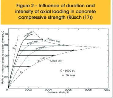
According Rüsch research [17], the concrete when subjected
to long lasting loading (t > 20minuts), undergoes compressive strength loss, a phenomenon similar to the relaxation (Fig.2). On the other hand, it is known that the Portland cement concrete, throughout his life, due to cement hydration, gains strength as it appears to the right of Fig. 3.
Thus, the load resistance of concrete can be easily provided as a
result of the product of two coeficients: bcc which depends on the rate of growth of strength of concrete compressive load from the date of application,and bc,sus, which depends on the permanence of load effect, also called the Rüsch effect in Brazil.
The growth rate of the concrete compressive strength, can be
Table 2 – Strength reduction factors utilized
for design of new structures
Factor ABNT NBR 6118
(Fusco [12])
fib Model Code 2010 [10]
gc 1,4 1,5
gc1 1,2 1,39
gc2 1,08 1,05
expressed by the model suggested by ib Model Code 2010,
namely:
(6)
bcc
=
÷÷øö çç è æ -*
=
s jc j
c
e
f
f
1 2828
, ,
where:
fc,j : the concrete compressive strength, measured in “j” days old; fc,28 concrete compressive strength, measured at 28 days;
s : coeficient that depends on the cement, the w /c ratio, and moisture conditions of the concrete.
For bc,sus value, the same ib Model Code 2010 suggests the fol-lowing model:
(7)
b
c,sus=
4 0, ,
,
0
,
96
0
,
12
ln{
72
(
)}
0
t
t
f
f
t c
t sus
c
=
-
×
×
-where:
fc,sus,t : compressive strength of concrete under sustained load at t age, counted from the date t0 of load application, in MPa;
fc,t0 : potential compressive strength of the concrete, at the time t0,
just before application of long lasting load in MPa.
In the case of ABNT NBR 6118: 2014, the value of bcc·bc,sus = 0,85 referred to t0=28days old, i.e., it is assumed that the growth of the concrete compressive strength from 28days to 50years will only,
bcc=1,17 (17%), wich corresponds to the index s = 0,16, and the decrease of compression strength of concrete due to the load ap-plied to 28 days until 50 years and maintained, the Rüsch effect, will be bc,sus = 0.73, whose product results bcc·bc,sus = 1,17 · 0,73 = 0,85. It is observed that it is very conservative value, because actually the growth of resistance of concrete from 28 days to 50 years al-ways exceeds 17%, and the decrease due this effect, according to Rüsch, would be at most 0.75.
In Fig. 4 it can be seen the resulting (bcc·bc,sus·fcm) of growth and
reduction effect, due long term loads, on the concrete strength, according Rüsch [17].
In this regard it should be noted that in the case of a loaded struc-ture, when analyzing the resistance from concrete cores, should be borne in mind that the resistance obtained may also be
un-der the inluence of the Rüsch effect. This fact will depend on the
structure loading history and also of its age, and there is still no clear consensus on how to consider this phenomenon in structural safety for existing structures.
4. Built structures assessment
Are presented some requirements of Brazilian and international standards recognized and respected in Brazil. The main focus is
to analyze the speciic technology issues and assessment and
Figure 2 – Influence of duration and
intensity of axial loading in concrete
compressive strength (Rüsch [17])
Figure 3 – Effects of age of loading
in concrete compressive strength
(Rüsch [17])
veriication of safety on existing structures, answering the following
basic questions:
n How to get the concrete characteristic strength equivalent to
the concrete samples from concrete cores?
n What are the key safety parameters to be considered in the
analysis of existing structures?
n What are the differences with respect to the design of the usual
parameters used for new structures
4.1 General cases and brazilian standards
To evaluate the strength of concrete compression on existing structures in order to verify the safety of the structure, should be employed the concepts and requirements of the standards ABNT NBR 8681:2003 [5], ABNT NBR 6118:2014 [6] and ABNT NBR 7680:2015 [18], which is the Brazilian standard most appropriate and most recent review on the concrete in situ via con-crete cores.
Therefore, considering that the steel strength does not change with time (provided it is kept in a good concrete), the unknown is greater when the characteristic concrete compressive strength, the 28 days of age agreed to fck and measured by the ABNT NBR 12655:2006 [16], ABNT NBR 5738:2003 [13] and ABNT NBR 5739:2007 [14].
In the case of existing structures this resistance should be judged
from the strength of the evidence taken from a different age 28 days, which may be termed core resistance fc,ext. To get fck from fc,ext, ABNT NBR 7680 prescribes a number of standard proce-dures that take into account the differences between the measured resistance in the concrete sampled from the concrete mixer and
subjected to ideal conditions of standard (fck) with the effective re-sistance of the concrete in the work (fc,ext), always less than “po-tential”.
4.1.1 First step
Therefore the irst step consists to inspect and analyze the struc -ture of obtaining a fck,equivalent from fc,ext, comparing it with the design strength, fck. Since fck,equivalent≥ fck design, analysis or veriication of safety can be considered met and approved.
In case that fck,equivalent < fck design , the Security check should pro-ceed with the second step, which is to check the safety with this new fck.
4.1.2 Second Step
For review and veriication of structural safety and global stability,
considering the ultimate limit state (ULS), ABNT NBR 6118:2014 on its entry 12.4.1, admits that in the case of fck obtained from extracted testimonies of structure, is adopted: fck obtained from ex-tracted testimonies of structure, is adopted:
Therefore, in usual cases, gc = 1,4/1,1 = 1,27, which is equivalent mathematically, to multiply the core result by 1.1, that is, increase it by 10%, once the core result represents better the effective
strength of the concrete near from the drilled region in the
struc-ture. For service states veriications purposes, shall be adopted gc =1,0.
If the safety check with this new gc 1,27 or 1,0 is met, the process over at this point.
4.1.3 Third step
If the line is not met, the security check can proceed to the third
step, which is the careful observation of the inished structure giv -ing geometrical measures position armor, armor rate, eccentricity tolerances, level and plumb, thickness slabs, or checking the ac-curacy of execution of the structure.
This last step is also advisable to review by sampling the
spe-ciic masses of materials, calculate the variability of the concrete
strength, carefully review the medium loads and variability as well as check the concurrency loads.
If the rigor of execution is within the tolerance limits as described in ABNT NBR 14931:2004 [19] (equivalent to Chapters 5 and 6 of ACI 318-11 and Chapter 8 of the ib Model Code 2010), the security
check may adopt mitigation coeficients of smaller concrete strength
1,27 and steel, gs 1.05 for ULS, and perform veriication with actual load values (effective density), effective concurrency, etc.
4.1.4 Fourth step
Staying non conformity of the structural safety for these conditions of use, choose from the following alternatives:
n determine the structure use restrictions; n provide repair and strengthening project; n decide on the partial or total demolition.
4.2 International standards
International standards have a methodology for analysis of similar existing structures and adhering to these concepts, especially with
the irst two steps, and also apply the last two steps.
4.2.1 ACI 318-11 Building code requirements for structural con-crete and commentary [20] e ACI 214.4R-10 Guide for obtaining cores and interpreting compressive strength results [21]
4.2.1.1 Structures under construction, irst step
During concrete control in a work in progress and forward the results of low results of resistance of concrete compression, the ACI 318-11 (Chapter 5, item 5.6.5) requests the extraction of three cores to the affected region.
If the mean value of the three cores strength is higher than 85% of the design resistance (f’c) and the values are below 75% of f’c, the structure shall be considered compliant and the process ends
here, and this procedure shall be taken as a irst step.
It is observed that this requirement is equivalent to multiply, respec-tively, the mean and the lowest value of the drilled cores by 1.18 and 1.33, i.e., fck,equivalent=1,18·fcm,ext or fck,equivalent=1,33·fc,minimum, ext.
4.2.1.2 Existing Structures, irst step
there are existing structures, ACI 318-11 (Chapter 20) requires estimation of equivalent strength f’c a more accurate way, through ACI 214.4R-10, on which should be considered some correction factors related to test effects, geometry and moisture of the core, as follows:
(9)
f
c= F
l/d· F
dia· F
mc· F
d· f
corewhere:
fc = corrected core strength;
fcore = drilled core strength, directly obtained in the compression test; Fl/d= correction factor due to core height/diameter ratio;
Fdia = correction factor due to core diameter; Fmc = correction factor due to moisture condition; Fd = correction factor due to drilling effect.
After correction of the compressive strength of each core, related to test variables and concrete intrinsic aspects, the standard ACI 214.4R-10 recommend two methods for obtaining inal equivalent compressive strength of concrete. They are:
• Tolerance factor method
(10)
(
) (
2)
2'
,eq c c a
c
f
K
s
Z
s
f
=
-
×
+
×
where:
f’c,eq = sample equivalent strength;
c
f = mean equivalent strength of tested drilled cores;
K= factor that takes in account the unilateral tolerance limit for a 10% quantile (ACI 214.4R-10, Table 9.2) which depends on the
desired reliability level in the design;
sc = sample standard deviation;
Z= factor that takes in account the uncertainty of the use of strength correction factors (ACI 214.4R-10, Table 9.3) and also depends on
the desired reliability level;
sa = standard deviation of strength correction factors (ACI 214.4R-10, Table 9.1).
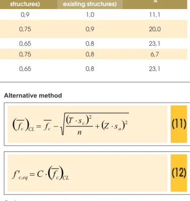
Alternative method
(11)
( )
(
) ( )
2 2a c
c CL
c
f
T
n
s
Z
s
f
=
-
×
+
×
(12)
( )
c CLeq
c,
C
f
f'
=
×
Onde:
f’c,eq = sample equivalent strength;
c
f = mean equivalent strength of tested cores;
T= factor obtained by Student t-distribution with (n-1) degrees of freedom, depending on desired reliability level (ACI 214.4R-10, Table 9.4);
sc= sample standard deviation;
Z= factor that takes in account the uncertainty of the use of strength correction factors (ACI 214.4R-10, Table 9.3) and also depends on
the desired reliability level;
sa = standard deviation of strength correction factors (ACI 214.4R-10, Tabela 9.1);
n = number of tested cores;
C = coeiciente related to intrinsic variability of materials strength in structure (ACI 214.4R-10, Table 9.5).
4.2.1.3 Second step, new structures under construction or existent
In case equivalent strength obtained by ACI 214.4R-10 does not
meet the design strength, safety must be veriied adopting new coeficients for reduction of concrete strength, named strength re
-duction factors (φ), present in ACI 318-11, Chapter 20, as shown in Table 3.
Although it is contained in the same concepts of the general case adopted in Brazilian standard, ACI 318-11 does not prescribe a
strength reduction coeficient for concrete, gc, and in safety
as-sessment of existing structures this coeficient reduction ranges
Table 3 – Strength reduction factors (
f
) according to ACI 318-11
Strength reduction factors
Chapter 9 (design of new
structures)
Chapter 20 (assessment of existing structures)
Difference %
Tension-controlled sections 0,9 1,0 11,1
Compression-controlled sections
Members with spiral
reinforcement 0,75 0,9 20,0
Others reinforced members 0,65 0,8 23,1
Shear and torsion 0,75 0,8 6,7
Bearing on concrete (except for post-tensioned anchorage
between 6,7% a 23,1% according to the main type of action, while in Brazil this reduction is fixed, conservative and equal to only 10% (with exception of old ABNT NBR 6118, from 1978 to 2003, that permitted a 15% reduction in some cases).
It is observed that in ACI 318-11 that the introduction to safe-ty in structural design differs from the adopted in ABNT NBR 6118. In the American code, the reduction factor (φ) is applied once only for steel and concrete strength. It is different from the Brazilian code procedure, in which the strength reduction factors are applied separately for concrete (gc) and steel (gs). For example, the axial compressive strength of a short column designed through ABNT NBR 6118:2014, is shown in eq.13, and for ACI-318-11, the strength is given by eq. 14.
(13)
s s yk c c ck
d
A
f
A
f
N
=
×
×
+
×
g
g
85
,
0
where:
Nd = Maximum axial load, design value;
fck = characteristic compressive strength of concrete;
gc = strength reduction factor of concrete; Ac = gross area of concrete section; fyk = yield characteristic strength of steel;
gs = strength reduction factor of concrete of steel; As = steel area.
(14)
(
)
[
c g st y st]
n
f
A
A
f
A
P
=
×
×
×
-
+
×
×
'max
,
,0
80
f
0
,
85
f
where:
φ.Pn,max = Maximum axial compressive strength, design value;
φ = Strength reduction factor;
f ‘c = specified compressive strength of concrete; Ag = gross area of concrete section;
Ast = total area of nonprestressed longitudinal reinforcement; fy = specified yield strength of reinforcement.
Therefore, comparing a short column with dimensions of
50x50cm, with fck of 35MPa and hypothetical CA-50 steel re-inforcement area of 37,70cm², using ABNT NBR 6118:2014, the design maximum axial load would be 6951,8kN, while the same element designed using ACI318-11 method, with re-duction factor (φ) equal to 0,65, results in axial compressive strength of 4789,48kN.
This demonstrates that the American code is more conservative than Brazilian code when assessing safety in design phase. However, assessing safety in Chapter 20 of ACI-318-11, the
strength reduction factor, or reduction coefficient (φ), can be
increased, which means to assume an increase of the existing element strength, due to the greater knowledge of structure actual state and the reduction of the admitted variability. For the hypothetical example above, item 20.2.5 of ACI-318-11
restricts the increase of coefficient (φ) to 0,80 at most, in
other words, an increase of 23% for the element compressive strength.
In ABNT NBR 6118 model, it is allowed a reduction of coeffi-cient gc from 1,4 to 1,27, when analyzing drilled concrete cores. In this case, altering only the factor related to concrete, the increase in the column strength would be of 7,8%. Along with another reduction in steel coefficient gs from 1,15 to 1,0, the total element strength increase would be of 11,3%, both cases far below from the values obtained by ACI method.
The third and fourth steps, cited previously in the general case are no explicit in ACI 318-11, but are clearly applicable. 4.2.3 ACI 562-13 Code requirements for evaluation, repair, and rehabilitation of concrete building and commentary [22]
This document proposes a preliminary assessment, including design review, construction data, reports and other available documents (research for used materials) and comparison of obtained information with all requirements of standards
appli-cable at the time of the project.
In case it is not possible to obtain sufficient information through design, specifications and other documents, consider concrete compressive strength values according to Table 6.3.1a, or ac-cording to values from drilled cores tested in laboratory, in or-der to acknowledge the actual concrete characteristics. When decided to test concrete drilled cores, it is recommended
Table 4 – Reliability index (
b
) according to fib Model code 2010 (p. 31 e 32) [10]
Limit state Safety assessment
model
Reference age
New structures
Existing
structures Notes
Serviceability (SLS)
Probabilistic safety
method 50 years b = 1,5 – Same assessment
criteria for new and existing structures Partial safety factor
method
Residual
service life – b = 1,5
Ultimate (ULS)
Probabilistic safety
method 50 years 3,1 ≤ b ≤ 4,3 3,1 ≤ b ≤ 3,8 Allows the reduction of minimum reliability for existing
structures Partial safety factor
to estimate concrete equivalent strength () through the equation:
(15)
(
)
ú
ú
û
ù
ê
ê
ë
é
+
×
×
-×
×
=
0
,
9
1
,1
28
20
,
0015
n
V
k
f
f
cc ceq
where:
fceq = equivalent compressive strength of concrete;
fc = mean core compressive strength, already corrected to consider
core diameter and seasoning conditions;
V = standard deviation of effective core strength; n = number of teste drilled cores;
Kc = modiication factor of coeficient of variation (depends of com -plying with ACI 562 Table 6.4.3).
After determining equivalent compressive strength, the structure safety should be assessed according to Chapter 20 of ACI 318-11. Thus, this document from ACI does not sum much more in-formation to ACI 318-11 and ACI 214.4R-10, only modifying the
procedure for obtaining equivalent strength (irst step) of concrete
in existing structures, and keeping the second step, and also the third and fourth steps from the general case.
4.2.4 ib Model code for concrete structures 2010
In assessment of existing structures, the ib Model Code 2010 [10] recommends that reduced values of gm are adopted, in order to account real active actions, effective dimensions and properties of materials used in the structure. For the factor gRd, which represents the product gRd1 · gRd2, equivalent to the product gc2 · gc3 (Brazilian code), the standard recommends assuming the value of 1,0. The gRd expresses a the uncertainties in geometry and calculation methods. It is noted that in the assessment of an existing structure, there are fewer uncertainties, allowing a reduction of this factor from 1,10 to 1,00.
For a pure probabilistic method, ib Model Code 2010 [10] suggests
that analysis should be based in reliability indexes, frow which will be obtained new safety factors. Table 4 presents some apectcs of
the reliability index (β) to be considered in design of new structures
and in assessment of existing structures.
4.2.5 EUROCODE 2. EN 1992. Dec. 2004. Design of con-crete structures. General rules and rules for buildings [23] e
EN 13791. Jan. 2007. Assessment of in-situ compressive strength in structures and precast concrete components [24]
Similarly, the EUROCODE 2 also recommend reduced values to be adopted for gc and gs, as long as uncertainties for strength cal-culations are minimized.
For determination of equivalent compressive strength (irst step), EN 13791 shall be applied, bringing calculation methods shown be-low in eqs. 16 and 17 bebe-low (it is always adopted the lesser value). • 15 cores or more
(16)
s
f
f
ck,is=
m(n),is-
,1
48
×
or
f
ck,is=
f
is,lowest+
4
where:
fck,is = sample equivalent strength;
fm(n),is = mean equivalent strength of tested cores; s = sample standard deviation;
fis,lowest = lowest compressive strength value of tested cores. • 3 a 14 cores
(17)
k
f
f
ck,is=
m(n),is-
or
f
ck,is=
f
is,lowest+
4
where:
fck,is = sample equivalent strength;
fm(n),is = mean corrected strength of tested cores;
k = factor that depends on the number of tested cores (EN 13791 Table 2);
fis,lowest = lowest compressive strength value of tested cores. Standard EN 13791 also recommend the correction of drilled cores compressive strength before the estimation of equivalent strength, in the same way as for ACI 214.4R-10, taking into account h/d ra-tio, diameter, seasoning effect, drilling effect, among others. In case the structure is submitted to rigorous quality control, as-suring that unfavorable deviations in element sections are within the limits of EN 1992 Table A.1, and if the coeficient of variation of concrete strength if lower than 10%, gc can be reduced from 1,5 to 1,4 (second step).
Even more, if the calculus of the design strength is based in critical geometric data (reduced by deviations and measured in the built structure), the recommendation is to reduce gc to 1,45. In the same
case, since that the coeficient of variation of the concrete strength
does not exceed 10%, could be adopted gc = 1,35.
When the evaluation of inished structure is based on tests and
in situ assays on the built structure (e.g. core testing), gc shall be
reduced by the conversion factor ƞ = 0,85 5.
Table 5 show the percentage of reduction suggested by EURO-CODE 2 for the safety factor gc.
Is realized that, in the case of EUROCODE, the new strength
re-duction coeficient, for the concrete resistance, used to safety as -sessment in built structures, since that is based in core testing, is equivalent to the Brazilian standard, i.e., equal to 1,27.
Table 5 – Utilized
g
cfactors in assessment of
existing structures (EUROCODE 2)
gc original gc reduced Difference (%)
1,5 1,4 7,1
1,5 1,45 3,4
1,5 1,35 11,1
1,5 1,3 15,4
Finishing this second step, if the safety does not to be checked, remaining the third and fourth steps from general case.
5. Exemple
So as to perform a benchmark between the different codes, is pres-ents below an exemple of a structure that knows that was designed with a f’c equal to 25MPa, where was adopted some data from core tests (Table 6), and then was applied the different codes in its analysis.
On the subject region, was obtained 8 cores, amount that complies
with minimum criteria of all codes used on this paper. For this, was used standard cores with 10cm of diameter and h/d ratio = 2. All values of strength are expressed in MPa (Mega Pascal).
5.1 First step: equivalent strength
If it were a building structure, for analysis according to ACI 318-11
(Chapter 5), should be used only 3 results in the region with prob-lems. For conservative reasons, of the eight available values, was used only 3 lower values.
From the results 15.4; 15.4 and 16,6MPa, is obtained
fc,equivalent = 18.6 MPa (multiplying the average of the results by 1.18). This condition does not meet the criteria of the standard,
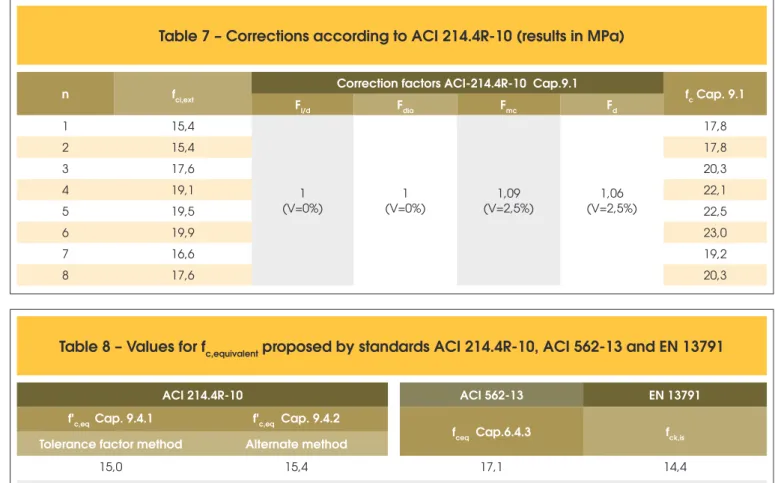
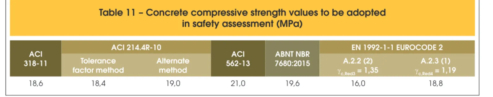
so there is the need to ind a new fc, equivalent to further analysis. In the Table 7 shows the correction of fci,ext proposed by ACI 214.4R-10, Chapter 9.1. For this practical example, we adopted a
95% conidence level.
From the corrected values of fc, there is need to ind the value of fc,equivalent. This parameter can be also obtained by ACI 214.4R-10, ACI 562-13 and EN 13791: 2007, as presented in Table 8.
5.2 Second step: safety assessment
After corrections and obtaining fc,equivalent, should be pro-ceed with the safety evaluation, as Chapter 20 of ACI 318-11 (or Ch. 5.4 of ACI 562-13 6) or the Eurocode 2.
According to the ACI 318-11, assuming that it is not a
reinforce-ment spiral column, it would be to modify the φ safety factor from
0.65 to 0.80, or a equivalent way is to top up the equivalent re-sistance (fceq) obtained in Table 8 at 1.23 (and continue using
φ = 0.65 in design veriication).
Table 6 – Data of drilled concrete cores
n 1 2 3 4 5 6 7 8
fci,ext 15,4 15,4 17,6 19,1 19,5 19,9 16,6 17,6
Table 7 – Corrections according to ACI 214.4R-10 (results in MPa)
n fci,ext Correction factors ACI-214.4R-10 Cap.9.1 fc Cap. 9.1
Fl/d Fdia Fmc Fd
1 15,4
1 (V=0%)
1 (V=0%)
1,09 (V=2,5%)
1,06 (V=2,5%)
17,8
2 15,4 17,8
3 17,6 20,3
4 19,1 22,1
5 19,5 22,5
6 19,9 23,0
7 16,6 19,2
8 17,6 20,3
Table 8 – Values for f
c,equivalentproposed by standards ACI 214.4R-10, ACI 562-13 and EN 13791
ACI 214.4R-10 ACI 562-13 EN 13791
f'c,eq Cap. 9.4.1 f'c,eq Cap. 9.4.2
fceq Cap.6.4.3 fck,is
Tolerance factor method Alternate method
15,0 15,4 17,1 14,4
NOTE: Standard EN 13791:2007 presumes the same adjustments for factors influencing drilled cores strength, such as: h/d ratio, diameter, moisture effects, drilling effects, among others.
Thus, the resistance values to be adopted under this concept would be shown in Table 9. From the point of view of EUROCODE 2, got the fck value, is by EN 13791 (even fceq ACI), then one should apply the security analysis criteria, as described els4ewhere. Similarly to run in the previous analysis in Table 10 are exposed patches of each of the items included in its Annex A.
There is, an overall assessment and with reference to this
exam-ple, the inal strength calculation ranged from 16MPa to 21MPa,
according to the criterion that is adopted, as shown in Table 11. This variability demonstrates, once again, the need to always use common sense in making decisions and seek to address the prob-lem with a holistic vision that aims to cover all variables without unduly hold a number obtained mathematically that, it is known and has been shown, can have meaning relative and not absolute. In the safety assessment, is checked that all codes consulted, allows a large reductions in their partial factors, since the variables after a structure is built, can be measured and considered in the desing as effective values. Thus, as there is no more a lot of unknowns and un-certainties, we can work with lower safety margin and more rational.
6. Final considerations
In the universe of the actual codes was observed several criteria,
however all the codes analyzed have in common the fact that the
reduction of certain portions of the partial coeficients is completely
feasible, without compromising structural safety.
However, to make use of new coeficients, it is necessary to have
a greater knowledge of the structure, and in this respect comes the important inspection activity, in which the rigor of execution, and the geometric parameters and quality of the materials must be properly checked.
The ib Model Code 2010, the composition of the material
coef-icient of resistance mitigation, considers explicitly, beyond the
portion related to the lack of resistance of the material, the por-tion that takes into account the geometric uncertainties that could possibly occur during execution . In this respect, if it is found that the structure was performed using geometry was within acceptable standards with concrete strength and knowledge of the structure
(through core), it would be able to effect the reduction of γm.
In the North American standard, as regards the strength of con-crete, the separation of material analysis and safety analysis is
evident, the irst item speciied by ACI 214.4R-10 or by ACI
562-13, dealing with correct inherent variables the test and the intrinsic properties of the concrete, while security is handled in accordance with Chapter 20 of ACI 318-11.
The Eurocode 2 operates analogously to ib Model Code 2010, allowing the reduction of γc coeficients since the geometry of the
structure has been performed accurately and such measures are considered in the calculation (characteristic measured by an effec-tive quality control in construction ).
The new text of ABNT NBR 7680: 2015 proves to be aligned with the main standards, and the correction of the extracted testimonies resistance values close to the results calculated by different meth-ods. However, for the analysis and reduction of the safety factor
(γc), yet must-carry as prescribed in ISO 6118: 2014.
On the statements relating to the inluence of age and long lasting loads
in the evaluation of concrete strength, these researchers found in the
Table 9 – Concrete equivalent compressive strength values for safety assessment,
according to ACI 318-11
ACI 318-11 Cap.20
ACI-214.4R-10 ACI 562-13
f'c,eq Cap. 9.4.1 f'c,eq Cap. 9.4.2
fceq Cap.6.4.3
Tolerance factor method Alternate method
18,4 19,0 21,0
Table 10 – Values of f
ckfor safety assesment,
according to EN 13791:2007 (assuming
g
c= 1,5)
fck,is EN 13791
A.2.2 (2)
gc,Red3 = 1,35
A.2.3 (1)
gc,Red3 = 1,19
14,4 16,0a 18,8a
a The presented values were increased, considering that in item A.2.2 (2)
fck = fck,is ·(gc/gc,Red3), and item A.2.3 (1) fck = fck,is ·(gc/gc,Red4).
Table 11 – Concrete compressive strength values to be adopted
in safety assessment (MPa)
ACI 318-11
ACI 214.4R-10
ACI 562-13
ABNT NBR 7680:2015
EN 1992-1-1 EUROCODE 2
Tolerance factor method
Alternate method
A.2.2 (2)
gc,Red3 = 1,35
A.2.3 (1)
gc,Red4 = 1,19
available literature, no mention of the need to backdate the strength of concrete at 28 days. No text was found considering the increase or decrease of the concrete strength after 28 days when considered in existing structures and aged lot or a little longer than 28 days.
A practical recommendation of the authors, would be considered in
the design veriication, the resistance obtained in the age of testing
without any regression, and proceed with the calculations accord-ing to standard theory.
General and holistic way, it was found that article that the secu-rity check of an existing structure is a complex and differentiated analysis, which depends on thorough knowledge of the structure and concrete technology, as well as the security concepts. In short, it is necessary that the professional engineering responsible for examining the existing structure know the variables involved in the process and learn to despise those who have worked, ensuring a reliable assessment which results in safe and economic decisions. In addition, to ensure the structural performance, often must be monitored the buildings and the inspections and necessary and periodic maintenance.
For new construction, the rationalization of construction, the Proj -ect Quality Control (PTC) and the Technological Control (CT) of the works should be encouraged and implemented, in order to obtain safe works within the design conditions and well build rules.
7. References
[1] ASSOCIAÇÃO BRASILEIRA DE NORMAS TÉCNICAS.
NBR 5674: Manutenção de ediicações. Requisitos para
o sistema de gestão de manutenção. Rio de Janeiro: ABNT, 2012.
[2] ASSOCIAÇÃO BRASILEIRA DE NORMAS TÉCNICAS.
NBR 15575: Ediicações habitacionais – Desempenho. Rio
de Janeiro: ABNT, 2012.
[3] HELENE, P. Contribuição à análise da resistência do
con-creto em estruturas existentes para ins de avaliação da se -gurança. ABECE Informa, São Paulo, n. 90, p.16-23, Mar/ Abr 2012.
[4] Comité Euro-International du Béton. Bulletin d’information n°. 192: Design and Assessment of Concrete Structures. Lausanne: CEB, 1989.
[5] ASSOCIAÇÃO BRASILEIRA DE NORMAS TÉCNICAS. NBR 8681 (Versão Corrigida: 2004): Ações e segurança nas estruturas. Procedimento. Rio de Janeiro: ABNT, 2003. [6] ASSOCIAÇÃO BRASILEIRA DE NORMAS TÉCNICAS.
NBR 6118: Projeto de estruturas de concreto. Procedimento.
Rio de Janeiro: ABNT, 2014.
[7] SILVA FILHO, L. C. P. & HELENE, P. Análise de Estruturas de Concreto com Problemas de Resistência e Fissuração. Capítulo 32. In: Geraldo C. Isaia. (Org.): Concreto: Ciên-cia e Tecnologia. 1 ed. São Paulo: IBRACON, 2011, v. 2, p. 1129-1174.
[8] Comité Euro-International du Béton. Bulletin d’information n°. 162: Assessment of Concrete Structures and Design Pro-cedures for Upgrading (Redesign). Lausanne: CEB, 1983.
[9] ZAGOTTIS, D. L. de. Introdução da Segurança no Projeto
Estrutural. São Paulo, EPUSP-PEF, 1974. 116 p.
[10] FÉDERATION INTERNATIONALE DU BÉTON. ib
(CEB-FIP) Model Code for Concrete Structures 2010. Lausanne: Ernst & Sohn, 2013.
[11] CREMONINI, R. A. Análise de Estruturas Acabadas: Contri-buição para a Determinação da Relação entre as Resistên-cias Potencial e Efetiva do Concreto. São Paulo, EPUSP, 1994 (tese de doutoramento)
[12] FUSCO, P. B. Controle da resistência do concreto. ABECE Informa, São Paulo, n. 89, p.12-19, Jan/Fev. 2012.
[13] ASSOCIAÇÃO BRASILEIRA DE NORMAS TÉCNICAS. NBR 5738: Concreto. Procedimento para moldagem e cura de corpos-de-prova. Rio de Janeiro: ABNT, 2003.
[14] ASSOCIAÇÃO BRASILEIRA DE NORMAS TÉCNICAS. NBR 5739: Concreto. Ensaios de compressão de corpos-de-prova cilíndricos. Rio de Janeiro: ABNT, 2007.
[15] GRAZIANO, F. P. Segurança estrutural e controle da re-sistência das estruturas de concreto. ABECE Informa, São Paulo, n. 91, p.16-23, Mai/Jun. 2012.
[16] ASSOCIAÇÃO BRASILEIRA DE NORMAS TÉCNICAS. NBR 12655: Concreto de cimento Portland. Preparo, controle e recebimento. Procedimento. Rio de Janeiro: ABNT, 2006.
[17] RÜSCH, H. Researches Toward a General Flexural Theory for Structural Concrete. ACI Journal, July 1960. p. 1-28. [18] ASSOCIAÇÃO BRASILEIRA DE NORMAS TÉCNICAS.
NBR 7680: Concreto – Extração, preparo, ensaio e análise
de testemunhos de estruturas de concreto. Parte 1: Re-sistência à compressão axial. Rio de Janeiro: ABNT, 2015. [19] ASSOCIAÇÃO BRASILEIRA DE NORMAS TÉCNICAS.
NBR 14931: Execução de estruturas de concreto – Procedi -mento. Rio de Janeiro: ABNT, 2004.
[20] AMERICAN CONCRETE INSTITUTE. ACI 318-11: Building Code Requirements for Structural Concrete and Commen-tary. Farmington Hills: ACI, 2011.
[21] AMERICAN CONCRETE INSTITUTE. ACI 214.4R-10: Guide for Obtaining Cores and Interpreting Compressive Strength Results. Farmington Hills: ACI, 2010.
[22] AMERICAN CONCRETE INSTITUTE. ACI 562-13: Code Requirements for Evaluation, Repair, and Rehabilitation of Concrete Building and Commentary. Farmington Hills: ACI, 2013.
[23] COMITE EUROPÉEN DE NORMALISATION. EUROCODE 2: Design of concrete structures. Part 1-1: General rules and rules for buildings. Brussels: CEN, 2004.
![Table 1 – Motives, scopes and actions that justify safety assessment of existing structures (Helene [3])](https://thumb-eu.123doks.com/thumbv2/123dok_br/18860915.417909/2.892.68.799.484.1015/table-motives-actions-justify-assessment-existing-structures-helene.webp)
![Table 2 shows the comparative values adopted by Brazilian stan- stan-dards compared to the requirements of ib Model Code 2010 [10].](https://thumb-eu.123doks.com/thumbv2/123dok_br/18860915.417909/4.892.63.439.176.375/table-comparative-values-adopted-brazilian-compared-requirements-model.webp)
![Table 4 – Reliability index ( b ) according to fib Model code 2010 (p. 31 e 32) [10]](https://thumb-eu.123doks.com/thumbv2/123dok_br/18860915.417909/8.892.58.440.379.708/table-reliability-index-b-according-fib-model-code.webp)