*e-mail: [email protected]
Microstructure, Material Flow and Tensile Properties
of A356 Alloy Thixoformed Parts
Emerson Reginaldo de Freitas, Elcio Geraldo Ferracini Júnior, Vinicius Perezin Piffer, Maurizio Ferrante*
Departamento de Engenharia de Materiais, Universidade Federal de São Carlos, Via Washington Luís, km 235, 13565-905 São Carlos - SP, Brazil
Received: May 10, 2004; Revised: October 8, 2004
The present work examines microstructure, tensile properties and quality (porosity level) of two thixoformed products, namely an assembly of three cylindrical rods from which tensile sam-ples were machined out, and a cup-shaped part. The material is an A356 aluminium alloy and the microstructural conditioning was carried out by the deformation - recrystallization technique. Additionally, the microstructures of an A356 ingot produced by the magnetic stirring process was also investigated. Results showed that solid fraction and soaking time in the semi-solid state deter-mine the thixoforming forces, that very low porosity levels can be achieved and minimized by the maintenance of high pressures during solidification, and that the material flow during injection in the mould is relatively homogeneous, except for the material conditioned by magnetic stirring. Physical simulation experiments of the thixoforming process (rods) showed a strong correlation between liquid segregation and porosity level. Finally, the tensile properties were shown to be much higher that those of permanent cast samples.
Keywords: semi-solid, A356 alloy, thixoextrusion, strength
1. Introduction
In general terms, the success of any thixoforming proc-ess is measured by the ability to produce defect free prod-ucts. Good formability, that is, negligible liquid segrega-tion and absence of defects result from adequate mould design, favourable rheological behaviour and laminar flow during mould filling1,2. These conditions depend on the for-mation of a non-dendritic billet microstructure and on thixoforming parameters such as gate flow velocity, mould temperature, lubrication, and many others3.
The production of non-dendritic microstructures can be achieved by two different groups of techniques4: i) solid-state methods, here called thermomechanical treatments (TMT), consisting basically of a cold or warm deformation step followed by a static recrystallization heat treatment and partial melting; ii) liquid alloy stirring, performed either through mechanical or by magnetic action, the latter tech-nique (MHD) being preferred when producing commercial quantities. Semi-solid state (SSS) forming techniques are mainly directed to aluminium alloys, particularly Al-Si, al-though work is underway on high strength wrought alloys such as AA2024, 7075 and 80165. However, albeit to a lesser
extent, some steels, magnesium and copper alloys are also targets for SSS technology. As for the solid/liquid ratio, its correct amount, hence the processing temperature depends of the process: thus, thixocasting operations are normally carried out at a solid fraction (fs) close to 0.5 or less, while thixoforging requires fs above 0.6.
The advantages of forming metallic alloys in the semi-solid state (SSS) are well-known: less mould wear due to the lower forming temperatures, possibility of welding and heat treating thixoformed parts (due to the absence of pores and shrinkage voids), excellent reproducibility of intricate design and complete filling of thin sections. The main drawback is still the raw material cost and of late a number of techniques in which the direct injection of microstructurally conditioned material, still in the SSS, are under development and as a consequence a number of new processes are being devel-oped, almost all based on the direct injection of semi-solid conditioned material, thus avoiding the re-melting step.
(b) of the most relevant process parameters is discussed.
Fi-nally, the microstructure and quality of the products are pre-sented and correlated to the process parameters.
2. Experimental Methods
2.1. Raw materials and microstructural conditioning
A commercial ingot of A356 (Al7Si0.3Mg) was re-melted, Sr-modified, inoculated with Ti-B and poured into rectangular (220 × 110 × 25 mm3) permanent moulds. Chemical composition is seen in Table 1. The alloy was homogenized at 540°C / 24 h and warm rolled (~ 300°C) to 30% thickness reduction. A second type of raw material, produced and supplied by ORMET INC, consisted of 100 mm diameter MHD A356 ingots, whose composition is also shown in Table 1.
2.2. Thixoforming
Two different parts were produced: i) a three rods as-sembly, which constitutes a typical example of thixoextruded products; ii) a cylindrical cup obtained by directly forming the billet in a conventional plunger-die tool. Inductive heat-ing was employed and the temperature measurement and control depended on chromel-alumel thermocouples which were inserted directly into the billets. The solid fraction was calculated by the Scheil equation.
Rods assembly: From both TMT plate and MHD billet, cylindrical billets (∅ 50 × 45 mm) were machined. The thixoextrusion process parameters were as follows:
• Force: 3.5 T;
• Plunger velocity: 250 mm s-1;
• Piston temperature: varied between 300 and 350°C; • Lubrication: dry graphite;
• Forming temperatures: 580°C (fs = 0.5) and 600°C (fs = 0.3);
• Billet soaking time: 10 to 25 min.
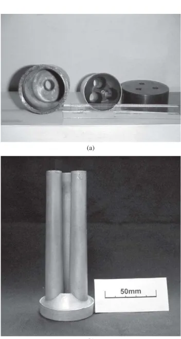
Figure 1 shows details of the die and of the extruded product, which is an assembly of three slightly tapered rods (2º) with average diameter and length equal to 14 and 120 mm, respectively.
Some interrupted thixoextrusion experiments were per-formed in order to analyse the material flow during mould filling.
Cylindrical cup: typical size is ∅ 43,6 (rim) × 26 mm, × 5 mm, taper of ~ 2º. Soaking time, forming force and plunger velocity had values very close to the ones employed in the thixoextrusion, whilst forming temperatures were 580 °C (fs = 0.5) and 590 °C (fs = 0.4). Thixoforming forces were detected by a 5 T load cell and processed by a Na-tional Instrument unit, Mod.SCI 1100. Figure 2 depicts two views of the product thus obtained.
2.3. Temperature homogenisation
Previous to the thixoextrusion experiments, a minimum
Table 1. Chemical composition of the A356 ingot wt. (%).
Sample Si Mg Fe Cu Mn
A356 TMT 7.10 0.40 0.12 0.01 0.007
A356 MHD 6.50 0.34 0.14 -
-Figure 1. Components of the thixoextrusion die and a typical three rods assembly.
(a)
2.4. Precipitation heat treatment
After thixoforming, the parts were subjected to precipi-tation hardening heat treatment (540 °C / 8 h; 155 °C / 4 h and 16 h).
2.5. Microstructural characterisation and part quality
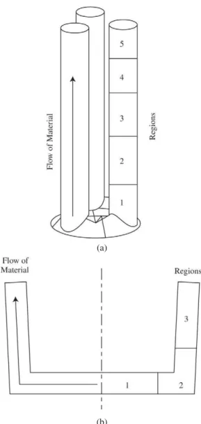
Optical microscopy and automatic image analysis (Im-age ProPlus™) were employed to quantitatively character-ise the microstructural features and defects such as pores and shrinkage voids. In order to quantify eventual micro-structural heterogeneity and uneven pore distribution throughout the samples, both rods and cups were divided into regions, as shown in Fig. 3, to which all observations will be correlated. The following microstructural param-eters were characterised: solid phase volume fraction (fs); Al-α particle size (D) and shape factor (F). The latter was calculated using the formula F = 4 π A / P2, where A and P
are respectively the average particle area and perimeter for unit area of the sample. This formula gives end values tend-ing to zero (rod) and 1 (sphere).
2.6. Tensile tests
Sub-size cylindrical tensile specimens (∅ 6 mm) were machined from the rods. The tests were performed in a INSTRON 5500-R universal testing machine
3. Results and Discussion
3.1. Raw materials and microstructural conditioning
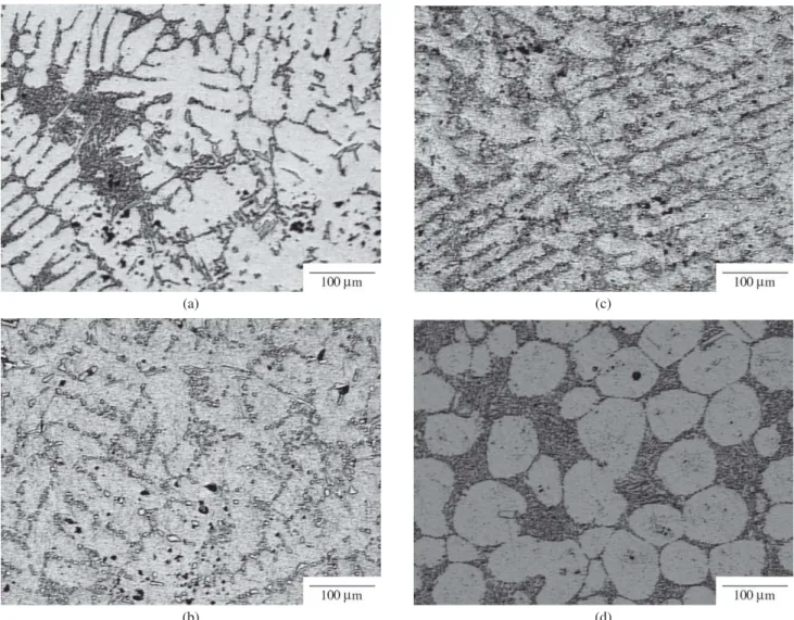
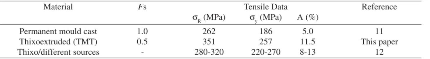
Figure 4 is a sequence depicting the typical microstruc-tural changes of the re-melted commercial A356 alloy in-got. From Fig. 4d it is apparent that the TMT here employed
Figure 2. Two different views of the thixoformed cup.
(b) Figure 3. a) Schematic of the three rods assembly and b) of the
cylindrical cup, showing the regions into which the samples were divided for microstructural and defects characterisation.
(b) (a)
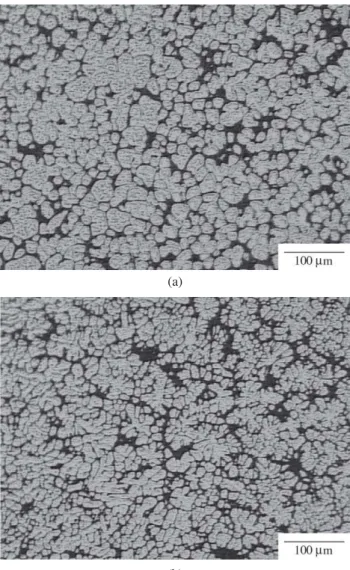
was greatly successful in producing the suitable microstruc-ture, that is, equiaxed and relatively small (D ~ 80 µm) Al-α particles, well insulated by the euctectic phase. Figure 5 depicts the typical microstructure of the as-cast, MHD-conditioned ingot. Individual particles are much smaller than those observed in the TMT samples but appear to form large aggregates of high contiguity. Furthermore, it is apparent that the ingot centre and periphery exhibit different micro-structures, more refined in the latter region but more spheroidized in the former.
3.2. Mechanical response of the semi-solid material
Curves of force against time were recorded during thixoforming of the cups (TMT alloy), see Fig. 6. It is ap-parent that the semi-solid alloy mechanical resistance is very small, that there is a pronounced solid fraction effect – see the difference between curves for fs = 0.4 and fs = 0.5 – and
that soaking times also affects the mechanical response, al-beit to a small extent. All curves have similar shapes where force increases with time up to a maximum which corre-sponds to the fracture of the solid skeleton formed by the approaching Al-α particles.
3.3. Microstructure and quality of the thixoformed parts
3.3.1. Thixoextruded rods
Figure 7 summarises the porosity measurements, includ-ing gas and shrinkage voids, performed in different region of the rods (refer to Fig. 3a). The alloy was microstructurally conditioned by TMT and the four samples were thixoformed employing the process parameters summarized in Table 2. Figure 7 shows that Rod 1 was characterised by incom-plete filling; therefore it solidified with no pressure and its porosity level was very high. However, the same figure
Figure 4. Microstructures of the A356 alloy: a) modified alloy; b) after homogenisation at 540°C / 24 h; c) after plastic deformation by warm rolling (~ 300°C) to 30% thickness reduction; d) after partial re-melting (580°C, corresponding to fs = 0.5) and water cooling.
(b) (a)
shows that when the extrusion pressure was maintained throughout solidification, a sharp decrease of porosity level was observed (compare Rod 1 with Rods 2, 3 and 4). As for the remaining two variables, that is, die temperature and soaking time, the former appears to be more important in terms of part quality, particularly when pore size is consid-ered, see Fig. 7b, which shows that the pores average area is much smaller than 2000 µm2 (corresponding to a pore diameter of 50 µm). As far fatigue life is concerned it was found that porosity ceases to be important for pore sizes below 50 µm6, hence the very good fatigue properties re-cently obtained on the present samples7.
Another general observation is that porosity is concen-trated at the rods ends, that is, positions 3 to 5, and it will be seen later that this occurrence is related to liquid segregation. The porosity level of typical permanent mould cast prod-ucts is around 1-2% with average pore size close to 70 µm8,9
Figure 5. Microstructures of the A356 MHD-conditioned billets in the as-cast condition: a) ingot centre; b) ingot periphery.
(a)
(b)
Figure 6. Curves of force against deformation time for two differ-ent solid fractions (0.4 and 0.5) and two differdiffer-ent soaking times at 590 and 580°C. Cups were produced employing a TMT A356 al-loy.
Figure 7. Porosity distribution: a) pore concentration; b) pores average size. The alloy was microstructurally conditioned by TMT. See text for description of the process variables employed for rods 1 to 4.
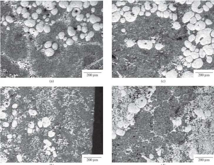
whilst for die cast parts the literature is less informative but levels are certainly higher. Therefore, the here obtained thixoextruded parts are characterised by porosity levels much lower than those of conventionally cast products. The liq-uid phase volume distribution in the rods produced by both TMT and MHD conditioned microstructure can be seen in Fig. 8a, whilst Fig. 8b shows the Al-α particle size distribu-tion in the same samples.
The following observations can be made: i) the MHD rods exhibit both a more intense segregation level and a larger particle size than the TMT - originated products, These parameters are probably interrelated, since to larger parti-cles corresponds a larger ‘free volume’ thus an easier path
for liquid segregation; ii) the liquid distribution coincides with the porosity level distribution, thus confirming the as-sociation between pores and segregated liquid. Finally it is important to point out that the reason why the experimental fs is somewhat smaller than that anticipated by the Scheil equation, is that the quenching rate was nor fast enough to preserve the actual solid/liquid ratio.
3.3.2. Thixoformed cups
Results of the quantitative metallographic observation are summarised in Fig. 9; they consist of graphs of the
spa-(a)
(b)
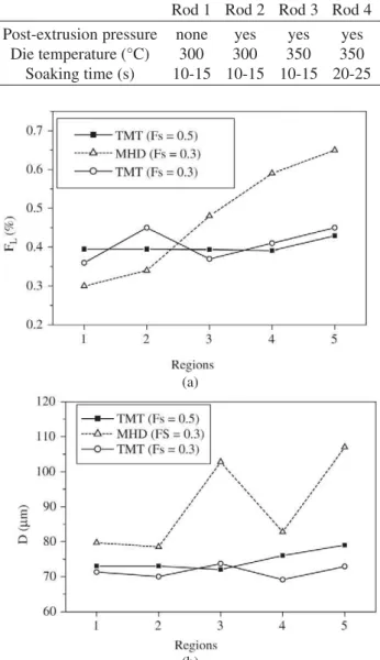
Table 2. Thixoextrusion process parameters.
Rod 1 Rod 2 Rod 3 Rod 4
Post-extrusion pressure none yes yes yes
Die temperature (°C) 300 300 350 350
Soaking time (s) 10-15 10-15 10-15 20-25
Figure 8. Spatial distribution within the rods of a) liquid fraction; b) particle size. Thixoextruded rods originated from TMT and from MHD conditioned A356 alloy, with fs = 0.5.
(a)
(b)
(c)
tial distribution of solid fraction, average particle size and shape factor, for samples produced with two different solid fraction (0.4 and 0.5) and soaking times equal to 10 and to 30 min. A number of comments can be made: i) the liquid segregation is reasonably low; its extreme value are fs = 0.58 - 0.60 in position 3 (wall) and fs = 0.61 - 0.69 in position 1 (base). Again the observed solid fractions are higher than the Schiel calculated values by the previously explained rea-son. Particle size is relatively constant within the cup vol-ume but it is influenced by the time spent in the SSS: diam-eters are in the range 65-70 µm for 10 min at 590°C, and 75-85 µm for 30 min, both at 590 and 580°C. That is, as for particle size, soaking time appears to be more important than soaking temperature, at least when the difference is only 10°C. More than to temperature, the size difference can be ascribed to the solid fraction: the sample kept at lower temperature (thus having a higher fs), exhibits a slightly
larger particle size than the sample in which these param-eters are reversed. Of course, size differences are minimal, but it must be borne in mind that if growth kinetics were defined by temperature alone, the cup thixoformed at 590 °C should exhibit coarser Al-α particles than the produced at 580°C.
As for the particle shape, observation shows that the F values are virtually equal and reasonably high (0.8), regard-less of different initial alloy conditions and positions within the sample.
3.4. Material flow during thixoextrusion
From the interrupted thixoextrusion experiments the following observations can be made with regard to both material flow and solid/liquid distribution: i) at the early stages of deformation a liquid front having an approximate thickness of 5 mm is formed; ii) behind this segregated
re-Figure 10. Exemples of solid/liquid distribution in different locations of the thixoextruded rods: a) conical interface between solid/liquid mixture and liquid phase - early stages of the thixoextrusion; b) liquid segregation adjacent to the mould wall; c) liquid pools close to the base of the rod; d) two groups of particles embedded into liquid phase separated by a liquid channel.
(a)
(b)
(c)
gion solid particles are observed and this ‘mixed microstruc-ture’ maintains a conical interface with the liquid front, see Fig. 10a which schematically depicts the transition ‘liquid to solid + liquid’; iii) further on, the frontal segregation de-creases but gives way to a liquid layer adjacent to the mould walls, as shown in Fig. 10b. This layer is approximately 3.0-3.5 mm thick when close to the front and between 1.0 and 2.0 mm thick midway the rod; iv) liquid segrega-tion was also observed just above the base of the rod; it appears either as liquid pools (Fig. 10c) or as liquid chan-nels separating region of solid/liquid coexistence (Fig. 10d); v) at the end of the thixoextrusion the segregated liquid is partially re-absorbed, giving rise to a relatively homogene-ous solid/liquid distribution, thus confirming, at least for the TMT-conditioned alloy, the quantitative microstructural observations summarized in Fig. 8a. An overall view of the material flow during thixoextrusion is shown in Fig. 11 which is a schematic of the solid liquid distribution from the early stages of deformation until complete mould fill-ing. It is important to point out that the formation of the liquid channels mentioned in (iii), above, had been identi-fied as one of the main softening modes acting during the deformation of semi-solid material10. Indeed, it was observed in that study that during parallel plates compression tests of cylindrical billets, the semi-solid skeleton fractures form-ing large aggregates of particles embedded in liquid phase, separated by liquid-filled channels. Finally, when these physical simulation experiments are analysed together with the quantitative microstructural data, see Fig. 8a, it can be concluded that for the TMT samples, porosity and liquid phase are homogeneously distributed, although in position 1 (end of the rod), porosity and liquid phase concentration are slightly higher. This observation confirms that liquid segregation constitutes the main source of voids and pores.
3.5. Tensile properties
The results of tensile tests performed on specimens machined from the thixoextruded rods modified by the de-formation-recrystallization technique can be seen in Table 3, which also contains data from other investigations.
It can be seen that the tensile properties of the thixoextruded material reported are perhaps 25-30% higher
than the permanent cast A356 alloy nominal values and of the same order than those reported in the literature on semi-solid products mechanical properties.
4. Conclusions
• Comparing the initial microstructures of semi-solid TMT and MHD A356 samples, it is apparent that the former exhibit larger particles but lower contiguity. Also, small microstructural differences between the MHD ingot centre and periphery were observed; • A difference from fs = 0.5 to 0.4 made a great
differ-ence on the TTM semi-solid billet mechanical re-sponse, whilst only a small decrease of resistance was observed on changing the soaking time from 10 to 30 min;
• The thixoformed rods exhibited a very small porosity level, except at its far end (opposite the metal entrance). A strong relationship was found between very low porosity and the maintenance of high pressure during solidification of the part;
• The TMT rods exhibited a very homogeneous solid/liquid distribution and a small particle size. Con-versely, the MHD rods showed accentuated liquid seg-regation towards the far end and a larger particle size throughout the rod;
• The thixoformed cups were characterised by homoge-neous solid/liquid distribution, and uniform particle shape and size;
Table 3. Tensile Properties of A356 T6 Specimens, compared with Literature Data.
Material Fs Tensile Data Reference
σR (MPa) σy (MPa) A (%)
Permanent mould cast 1.0 262 186 5.0 11
Thixoextruded (TMT) 0.5 351 257 11.5 This paper
Thixo/different sources - 280-320 220-270 8-13 12
• Regions of higher porosity coincide with regions of liquid segregation;
• Tensile properties are much higher than those meas-ured on permanent cast A356 samples.
References
1. Kopp, R.; Shimahara, H Proc. 7th Int. Conf. on Advanced Semi-Solid Processing of Alloys and Composites, Tsukuba (J), p. 57, september/2002.
2. Flemings, M.C. Metall. Trans. A, 22A, p. 957-980, 1991. 3. Sharma, K.C.; Ferreira, J.H.; Govender, G.; Damm, O.; Proc. 6th Int. Conf. on Semi-Solid Processing of Alloys and Composites, Turim (I), p. 253, september/2000. 4. Kirkwood, D. H. Int. Mat. Rev. 39, p. 173-189, 1994. 5. Atkinson, H.V.; Kapranos, P.; Kirkwood, D.H. Proc. 6th
Int. Conf. on Semi-Solid Processing of Alloys and
Com-posites, Turim (I), p. 443, september/2000.
6. Bouffière, J-Y.; Savelli S.; Jouneau, P.H.; Maire, E.; Fougères, R. Mater. Sci. Eng A, 316, p. 115-126, 2001. 7. Freitas, E.; Ferrante, M.; da Silva, V.F.; Bose Filho, W.; Spinelli, D. Proc. Int. Conf. on Advances in Materials and Processing Technologies, Dublin, (EI), p. 1481, july/2003. 8. Samuel, A.M.; Samuel, F.H. Metall. Trans. A, 24A,
p. 1857-1862, 1993.
9. Wang, L.; Shivkumar, S. J. Mater. Science, v. 30, p. 1584-1594, 1995.
10. Freitas, E.R.; Ferrante, M. Acta Mater. v. 49, p. 3839-3847, 2001.
11. Metals Handbook, v. 2, ASM, Metals Park – Ohio. 12. Atkinson, H.V.; Liu, D. Proc. 7th int. Conf. on Advanced