Journal of Science and Technology
ISSN 1905-7873 Available online at www.mijst.mju.ac.th Full Paper
Wave run-up on sandbag slopes
Thamnoon Rasmeemasmuang 1,*, Wanich Chuenjai 1 and Winyu Rattanapitikon2
1 Department of Civil Engineering, Burapha University, Chonburi, Thailand
2 Sirindhorn International Institute of Technology, Thammasat University, Pathumthani, Thailand * Corresponding author, e-mail: [email protected]
Received: 15 April 2013 / Accepted: 12 March 2014 / Published: 17 March 2014
Abstract: On occasions, sandbag revetments are temporarily applied to armour sandy beaches from erosion. Nevertheless, an empirical formula to determine the wave run-up height on sandbag slopes has not been available heretofore. In this study a wave run-up formula which considers the roughness of slope surfaces is proposed for the case of sandbag slopes. A series of laboratory experiments on the wave run-up on smooth slopes and sandbag slopes were conducted in a regular-wave flume, leading to the finding of empirical parameters for the formula. The proposed empirical formula is applicable to wave steepness ranging from 0.01 to 0.14 and to the thickness of placed sandbags relative to the wave height ranging from 0.17 to 3.0. The study shows that the wave run-up height computed by the formula for the sandbag slopes is 26-40% lower than that computed by the formula for the smooth slopes.
Keywords: wave run-up, coastal protection, sandbag revetment, wave steepness, surf similarity parameter
_______________________________________________________________________________________
INTRODUCTION
prediction of the wave run-up is therefore necessary for effective coastal zone management and coastal disaster warning [5].
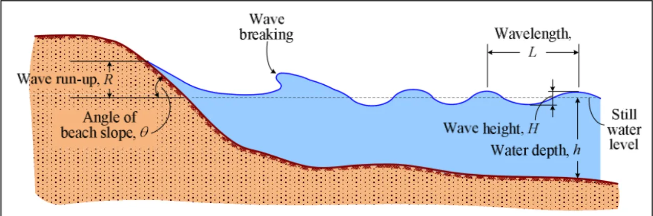
Figure 1. Definition of wave run-up
Previous studies on the wave run-up over sloping structures were mainly performed in laboratories. Hunt [1] carried out experiments on regular wave run-up on impervious, smooth slopes and proposed an empirical formula for predicting wave run-up height. Based on the experimental results, it was found that the wave run-up height normalised by deepwater wave height (R/Ho) is a
function of the deepwater surf similarity parameter (o). Battjes and Roos [6] conducted similar
laboratory experiments and obtained the results consistent with Hunt’s. Besides studies of the regular waves, there were several studies of irregular waves. For instance, Ahrens [7] developed a method to estimate irregular wave run-up on smooth slopes based on results of several laboratory studies. Polynomial equations involving wave steepness were presented for computing representative wave run-up heights. Mase [3] performed an extensive series of laboratory tests on random wave run-up on smooth, gentle slopes and empirically determined a formula for predicting representative run-up heights. The formula was proposed as a power function of surf similarity.
In addition to the studies on wave run-up on smooth inclined planes, the behaviour of wave run-up on non-smooth slopes was also investigated. Van der Meer and Stam [8] conducted experiments on random wave run-up on rock slopes ranging from 1:1.15 to 1:4. There were four tested cross sections varying in thicknesses of the armour layer and the filter layer. Two relationships between relative wave run-up and surf similarity parameter were proposed. For a small surf similarity parameter (smaller than about 1.5), a linear relationship was taken, whereas for a larger surf similarity parameter (larger than about 1.5), the relationship was described simply by a power function, which resembles Mase’s form [3]. Shankar and Jayaratne [9] carried out a series of hydraulic model tests to investigate the influences of roughness, layer thickness and porosity on the wave run-up on impermeable and permeable breakwaters. The surfaces of the breakwater models were made rough with gravels and welded wire meshes. Neelamani and Sandhya [10] investigated the wave run-up on plane, dentate and serrated seawalls that were fabricated using aluminum boxes zigzaggedly fixed on steel sheets. It was found that the sloping serrated seawall was capable of dissipating the wave energy better than the plane and dentate seawalls.
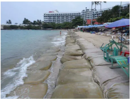
from waves and strong currents [2]. One of the advantages of sandbag revetment is that, unlike rock revetment, it still provides an easy access way for people to walk across to the beach and the sea. During the past decades, a few studies (e.g. [11-13]) were performed on the application of sandbags. However, they are largely related to typical aspects in terms of structural design and construction. Studies on wave run-up on sandbag slopes have been very limited. Kobayashi and Jacobs [11] adopted an empirical formula of Ahrens and McCartney [14] for predicting wave run-up on sandbag slopes. Only the surf similarity parameter with two empirical coefficients is used in the formula, and it may not be applicable for general cases because the thickness of sandbags is not taken into account in the formula. Heretofore, there have been no formulas accounting for the effect of sandbag thickness on the wave run-up.
Figure 2. Example of sandbag revetment at northern Pattaya beach, Chonburi province (photo taken on February 7, 2013)
The objective of the present study is to develop an empirical formula, in which the roughness of the slope surface is taken into account, for the wave run-up on sandbag slopes. The empirical parameters in the formula are obtained from the results of laboratory experiments on wave run-up on smooth slopes and sandbag slopes conducted in a wave flume. The accuracy of the formula is also discussed.
EXPERIMENTAL SET-UP
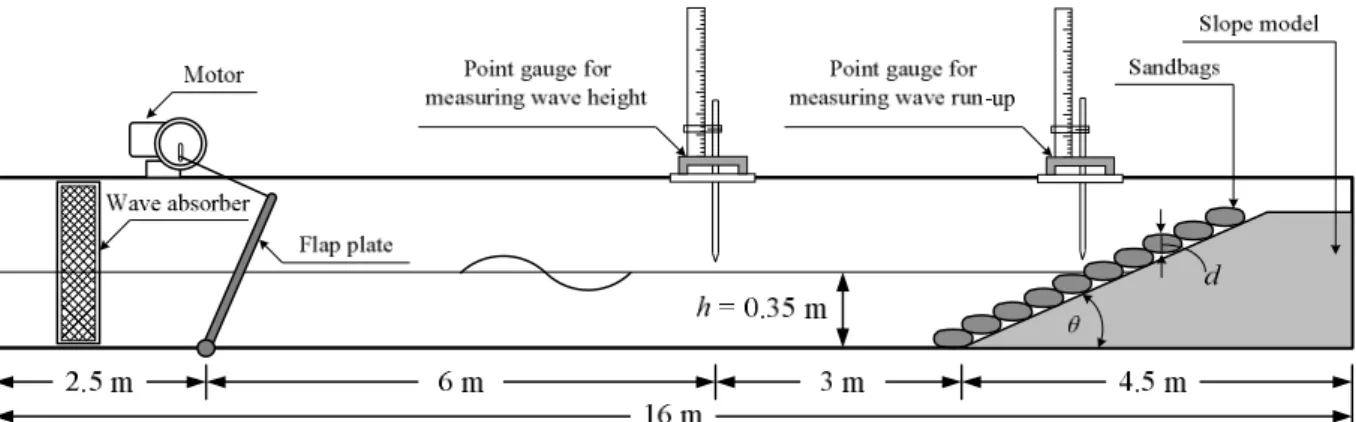
Figure 3. Experimental set-up (wave flume)
Two types of slope surface, i.e. smooth surface and sandbag surface, were used in the study. The smooth-surfaced slope was built with a 2.55-m-long stainless steel plate, whilst for the sandbag surface, linen bags filled with sand were arranged on the slope model. In order to study the effects of thickness of the placed sandbags on wave run-up, bags with five different widths (50, 75, 100, 125 and 150 mm) were used. The heights of the placed sandbags corresponding to their widths were 22.5, 28.5, 44.0, 52.5 and 61.0 mm respectively. The slope angles were 15°, 17.5°, 20°, 22.5° and 25°. All experimental conditions are summarised in Table 1.
Table 1. Experimental conditions
Parameter Smooth slope Sandbag slope
Water depth, h (mm) 350
Frequency of wave generation (Hz) 0.83, 1.00, 1.17, 1.33, 1.50, 1.67 Corresponding wave period, T (s) 1.20, 1.00, 0.86, 0.75, 0.67, 0.60 Stroke of crank disk (mm) 80, 100, 120, 140, 160, 180, 200 Wave height at the toe of the structure, H (mm) 20–140
Wave steepness, H L 0.01–0.14
Slope angle, 15°, 17.5°, 20°, 22.5°, 25°
Thickness of the placed sandbag, d (mm) - 22.5, 28.5, 44, 52.5, 61
Number of test cases 210 1,050
1) A burst of a small number of waves was generated and the generator stopped between bursts to allow the reflected waves to die down. The wave height in each case was measured after the initial unsteady wave transients had died down. The measurements were performed for about 5 minutes or prior to the changing of wave pattern due to the wave reflection. The wave height and wave run-up were measured ten times each. The values of wave height and wave run-up used in the analysis represent an average from each case.
2) The experiments were carried out under limited wave and beach conditions. As the wave reflection on a plane beach varies with the surf similarity parameter ( ), the experiments were performed under small (small slope and large wave steepness) conditions. From preliminary tests on plane beaches, it was found that the influence of wave reflection is significant when > 3.
3) To avoid the occurrence of wave rundown and wave reflection in front of the slope, the incident wave height was measured at 3 m seaward from the toe of the slope, and the measurement was applied as the incident wave height at the toe of the slope.
FORMULA DEVELOPMENT
The measured run-up heights (R) acquired were used to develop a new run-up height formula. In total, 210 test cases for smooth slope conditions and 1,050 test cases for sandbag slope conditions were used in the development. Analysis and discussion of each condition are presented as follows.
Smooth Slope Conditions
According to the dimensional analysis [15], a wave run-up height R on a slope is expressed as:
1 ,tan , , ,
R f H h d K
H L H H H
(1)
where R is the wave run-up height, H is the wave height at the structure toe, L is the wavelength, tan is the beach or structure slope, h is the water depth at the toe of the slope, d is the roughness height, and K is the permeability of the structural material with the unit of square metre, which is related to the intrinsic permeability (k) with the unit of metre per second (K k g , where is the kinematic viscosity of water and g is the acceleration of gravity).
For the wave run-up on smooth and impermeable slopes, the possible related parameters are /
H L, tan and h H . As most of the existing formulas for computing R/H are proposed in terms of H L/ and tan (excluding h H), the parameter H L/ seems to be more significant than the term h H. Moreover, Saville [16] found that the effect of h H is negligible when h H is larger than 3.0. In the present experiment the h Hvalues in most of the data are less than 3.0; therefore, the term h H is not considered in this study. Thus, for a smooth and impermeable slope, Equation 1 becomes:
2 ,tan
R f H
H L
Based on some existing formulas (e.g. the formulas of Hunt [1] and Mase [3]), a common parameter that is usually used to describe R on a smooth slope is the surf similarity parameter. Therefore, the function in Equation 2 can be simplified as:
3 3
/
tan f
L H f H
R
(3)
where tan/ H/L is the surf similarity parameter or the Iribarren Number [17]. In this study the wave length (L) was calculated based on the small amplitude wave theory.
Only the measured data of the wave run-up on smooth slopes are used in this case. The experiments cover a range of wave steepness from 0.01 to 0.14 (0.01H/L0.14) and slope angle from 15o to 25o (15o 25o). The relationship between the measured R/H and (in the log-log scale) is shown in Figure 4, which shows that the relationship can be fitted with a power function which is a straight line on a logarithmic graph. The equation of the fitted line can be written in a general form as:
b
R a
H (4)
where a and b are the coefficients. From the regression analysis of log(R/H) and log(), the values of a and b are 0.98 and 0.94 respectively. The best-fitted line is shown as the solid line in Figure 4. Thus, the formula for wave run-up on a smooth, impermeable slope is expressed as:
0.94
0.98 R
H (5)
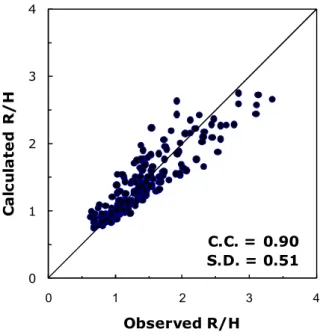
Figure 5 shows a comparison of observed and calculated relative run-up heights. Both the measured and the calculated values agree well, with a correlation coefficient (C.C.) of 0.90 between both values and a standard deviation (S.D.) of 0.51. It is obviously seen that the deviation increases as the relative run-up height increases. In the tests the relative run-up height was larger (e.g. R H > 2.0) as the wave steepness got smaller (e.g. H L < 0.03) and the surf similarity parameter got larger (e.g. > 2.5). In a similar manner, the scatter of the prediction and the observation under the condition of small wave steepness and high surf similarity parameter is also found in other studies (e.g. [3, 7, 8]).
An attempt was made to relate R with the deep-water wave parameters (i.e. R/Ho versus o
), as in the formula of Hunt [1]. The result is R/Ho 0.94o, which is very close to the formula
y = 0.98x0.94 0.1
1 10
0.1 1 10
R / H ξ 0 1 2 3 4
0 1 2 3 4
C a lc u la te d R /H Observed R/H
C.C. = 0.90 S.D. = 0.51
Figure 4. Relationship between relative run-up height (R H) and surf similarity parameter () for the case of smooth slopes
Figure 5. Comparison of observations and predictions of relative run-up height for the case of smooth slopes
Sandbag Slope Conditions
For wave run-up on sandbags, the possible related parameters are H /L, tan, d/H and H
K/ . The effect of structure permeability is usually introduced when the barrier is rock or concrete units. However, sandbags (used in the present study) are also used as barrier in flood control. This means that the permeability of sandbags should be very small. Therefore, the effect of
H
K/ is not considered in this study. A wave run-up formula considering the roughness height was proposed as Equation 6:
1 1 2
c b
R a a d
H H
(6)
where a1 and b are parameters from the case of the aforementioned smooth slopes, and are equal to
0.98 and 0.94 respectively, while a2 and c are empirical parameters for the term of relative
roughness height (d H). In this study the heights of the placed sandbags shown in Table 1 are applied for the roughness height (d). It is noted that Equation 6 can be applied for the case of smooth slopes as well by putting the value of d as zero. (Then Equation 6 will revert to Equation 5.)
Equation 6 can be rearranged as:
2 1
1
c b
R H a d
a H
(7)
the values of the empirical parameters (a2 and c), the relationship between the measured and d H is plotted (Figure 6), and then the values of a2 and c are determined by the least square
method. Thus, the formula for the wave run-up height on sandbag slopes in this study becomes:
0.15 0.94
0.98 1 0.34
R d
H H
(8)
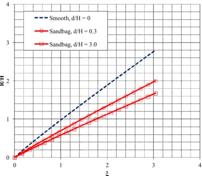
From the experimental results, it is obvious that the roughness of the slope face influences the height of wave run-up. On sandbag slopes, the wave run-up values are lower than those on the smooth slopes. Furthermore, at the same beach slope, the value decreases as the thickness of the placed sandbags increases. It is evident that the energy of the wave rushing up the slope is dissipated proportionately as the roughness height of the slope increases.
Figure 7 shows a comparison of the observed relative run-up values and those calculated by Equation 8. The calculated results agree well with the observed values, with a correlation coefficient of 0.86 between both values and a standard deviation of 0.35. From the experimental results, the term 1 0.34
d H
0.15 ranges from 0.60 to 0.74, which can be interpreted that the relative run-up height calculated by Equation 8 is 26-40% smaller than that calculated by Equation 5.y = 0.34x0.15
0.1 1 10
0.1 1 10
y
d/H
0.0 0.5 1.0 1.5 2.0 2.5
0.0 0.5 1.0 1.5 2.0 2.5
C
a
lc
u
la
te
d
R
/
H
Observed R/H
C.C. = 0.86 S.D. = 0.35
Figure 6. Relationship between relative roughness height (d H ) and value of in Equation 7 for the case of sandbag slopes
Figure 7. Comparison of observed and predicted relative run-up heights for the case of sandbag slopes
respectively than those on smooth slopes. Therefore, in the design of sandbag revetments the wave run-up formula that considers the roughness (thickness of placed sandbags) would be more accurate in determining the height of the structures. Accordingly, the economy of construction materials would be achieved.
0 1 2 3 4
0 1 2 3 4
R
/H
ξ
Smooth, d/H = 0 Sandbag, d/H = 0.3 Sandbag, d/H = 3.0
Figure 8. Relationship between surf similarity parameter () and relative wave run-up (R H) computed by Equation 8
CONCLUSIONS
Studies on wave run-up on sandbag slopes have been very limited. There has been no formula accounting for the effect of sandbag thickness on wave run-up. This study develops an empirical formula in which the roughness of slope surfaces is taken into account for wave run-up on sandbag slopes. The development of the formula consists of two stages. Firstly, the measured experimental data of wave run-up on smooth slopes were analysed to identify a basic form of the wave run-up. After that, based on the measured data of the run-up on sandbag slopes, the term of the roughness effect was derived and included into the basic formula, which gives good agreement with the measured data. The proposed empirical formula is applicable to the wave steepness ranging from 0.01 to 0.14 and the thickness of placed sandbags relative to the wave height ranging from 0.17 to 3.0.
ACKNOWLEDGEMENTS
This research was supported by the Faculty of Engineering, Burapha University (Contract no. 12/2555).
REFERENCES
2. U.S. Army Corps of Engineers, “Coastal Engineering Manual”, U.S. Army Engineer Research and Development Center, Washington, D.C., 2002, Part II, Chapter 4.
3. H. Mase, “Random wave runup height on gentle slope”, J. Waterway Port Coastal Ocean Eng., 1989, 115, 649-661.
4. J. P. Ahrens and W. N. Seelig, “Wave runup on beaches”, Proceedings of 25th Coastal Engineering Conference, 1996, Orlando (FL), USA, pp.981-993.
5. S. J. Na, K. D. Do and K. D. Suh, “Forecast of wave run-up on coastal structure using offshore wave forecast data”, Coastal Eng., 2011, 58, 739-748.
6. J. A. Battjes and A. Roos, “Characteristics of flow in run-up of periodic waves”, Report No. 75-3 (Ch. 45), Faculty of Engineering and Geosciences, Delft University of Technology, Deft (Netherlands), 1975.
7. J. P. Ahrens, “Irregular Wave Run-up on Smooth Slopes”, U.S. Army Coastal Engineering Research Center, Springfield (VA), 1981.
8. J. W. van der Meer and C. J. M. Stam, “Wave runup on smooth and rock slopes of coastal structures”, J. Waterway Port Coastal Ocean Eng., 1992, 118, 534-550.
9. N. J. Shankar and M. P. R. Jayaratne, “Wave run-up and overtopping on smooth and rough slopes of coastal structures”, Ocean Eng., 2003, 30, 221-238.
10. S. Neelamani and N. Sandhya, “Wave reflection, run-up, run-down and pressures on plane, dentated and serrated seawalls”, Coastal Eng. J., 2004, 46, 141-170.
11. N. Kobayashi and B. K. Jacobs, “Stability of armor units on composite slopes”, J. Waterway Port Coastal Ocean Eng., 1985, 111, 880-894.
12. P. E. Gadd, “Sandbag slope protection: Design, construction, and performance”, in “Arctic Coastal Processes and Slope Protection Design” (Ed. A. C. T. Chen and C. B. Leidersdorf), American Society of Civil Engineers, New York, 1988, pp.145-165.
13. W. P. Hornsey, J. T. Carley, I. R. Coghlan and R. J. Cox, “Geotextile sand container shoreline protection systems: Design and application”, Geotextil. Geomembr., 2011, 29, 425-439.
14. J. P. Ahrens and B. L. McCartney, “Wave period effect on the stability of riprap”, Proceedings of Conference on Civil Engineering in the Oceans/III, Vol. 2, 1975, Newark (DE), USA, pp.1019-1034.
15. Y. Tsuchiya, Y. Kawata and T. Yashita, “Effects of roughness and permeability on wave run-up”, Proceedings of 25th Japanese Conference on Coastal Engineering, 1978, Yokohama, Japan, pp.160-164 (in Japanese).
16. T. Saville, Jr., “Wave run-up on shore structures”, J. Waterways Harbors Div., 1956, 82, 1-14. 17. J. A. Battjes, “Surf similarity”, Proceedings of 14th Coastal Engineering Conference, 1974,
Copenhagen, Denmark, pp.466-480.