American Journal of Applied Sciences 5 (2): 106-109, 2008 ISSN 1546-9239
© 2008 Science Publications
Corresponding Author: M. Labibzadeh, Department of Civil Engineering, K.N. Toosi University of Technology, Tehran, Iran
106
An Assessment of Compressive Size Effect of Plane Concrete Using Combination of
Micro-Plane Damage Based Model and 3D Finite Elements Approach
1
M. Labibzadeh,
1S. A. Sadrnejad, and
2M. Naisipour
1Department of Civil Engineering, K.N. Toosi University of Technology, Tehran, Iran
2Department of civil engineering, university of science and technology, Tehran, Iran
Abstract: In recent years, the material behavior dependence of laboratory concrete specimens built
with the same concrete mixture under the same load conditions to their geometrical sizes is well established. This phenomenon which is observed not only in concrete but also in most quasi-brittle materials such as rock, ceramic or composite materials is now called as size effect. Many of the existing structural analyzing codes are not able to consider this important feature of concrete structures especially under compressive loadings. However we know that the main purpose of concrete application in structural members is to resist compression. The aim of this study is to show the ability of author's recently developed 3D finite elements code equipped with the proposed author's newly micro-planes damage based model for considering of compressive size effect of plane concrete. To do so, two different sizes of cubic concrete specimens are modeled with mentioned code under the uniaxial compressive test and their fracture mechanisms, pre-peak and post-peak strain-stress paths are investigated. Obtained results reveal the good coincidence with experimental evidences. In fact, the combination of proposed micro-planes damage based model and developed presented 3D finite elements technique creates a powerful numerical tool to capture and predict precisely strain localization and fracture mechanism in the specimens and consequently to assess properly the compressive size effect of plane concrete in analysis and design.
Key words: Micro-Planes, damage, concrete, finite elements, size effect, uniaxial compressive test
INTRODUCTION
It is a well-known fact that there is an effect of size differences in behavior of specimens made with quasi-brittle materials such as concrete, rock, ice, ceramic and composite materials under loads [1, 2 and 3]. More specially, the material behavior of laboratory size specimens differs from that of larger structural members used in construction of real structures. The difference is a direct consequence of energy release into a finite-size fracture process zone (damage localized zone). This phenomenon which is observed mostly in quasi-brittle materials is called as strain localization. The size of this fracture process zone and consequently the amount of fracture energy release are dependent on geometrical size of the specimen.
Presently, most analyzing codes for concrete structures do not consider the effect of size in analysis. Since quasi-brittle materials such as concrete fail by formation and propagation of cracks, size effect has to be implemented.
Some concrete structural members such as central plan position columns in concrete frame buildings experience compressive loading condition.
Approximately similar situation can be simulated in a concrete laboratory specimen under uniaxial compressive test. Fracture mechanics based formulation of size effect theory has not been studied rigorously for such compressive loaded members.
In compressive failure of concrete, size effect is quite apparent. Though the behavior of compressive failure has been studied extensively, the failure mechanism and its size effect have been insufficiently studied when compared to tensile failure mechanism.
The main object of the presented research is to achieve a numerical model which is able to simulate properly the compressive size effect of plane concrete in structural analysis of concrete structures by means of a combination of author's proposed newly micro-planes damage based model [4] and recently author's developed 3D finite elements code [5]. To investigate the capability of presented numerical model [6] in this domain, two different sizes of cubic concrete specimens are modeled with mentioned code under the uniaxial compressive test and their fracture mechanisms, pre-peak and post-peak strain-stress paths are investigated. Obtained
Open
Access
Author Manuscript
SCI-PUBLICATIONS
Author Manuscrip
Am. J. Applied Sci., 5 (2): 106-109, 2008
107 results reveal the good coincidence with experimental evidences. In fact, the combination of proposed micro-planes damage based model and developed 3D finite elements technique creates a powerful numerical tool to capture and predict precisely strain localization and fracture mechanism in the specimens and consequently to assess properly the compressive size effect of plane concrete in analysis.
Strain localization and size effect: Concrete
compressive size effect, in fact, is the dependence of specimen fracture mechanism under compressive load to its geometrical sizes. In other words, if we have for example two concrete laboratory cube specimens with the same material and cross sections but with two different heights, they will be show different fracture mechanism and consequently different responses under the same uniaxial compressive test. This difference in fracture mechanism and fracture energy release levels can be observed for example in differences between two mean obtained strain/ stress curves. Fracture energy can be defined as area under the average axial strain/ stress curve mainly after the peak point. The difference in fracture energy release levels is due to the difference in fracture mechanisms and fracture paths in two specimens. In fact, the fracture energy is consumed for the growth of crack through the concrete specimen. There is a close relation between the compressive size effect of concrete and the strain localization phenomenon which is observed in concrete specimen during affection of uniaxial compressive load. At the beginning stage of uniaxial compressive test, there exist approximately uniform distributed cracks in the cross section of the specimen. By increasing the compressive load on the specimen, the cracks gradually become longer and connect to each others and their distribution within the section start to become non-uniform. Near to the maximum load level, the cracks are focused in a narrow band in some part of the section and strain localization is occurred in this region. The width of this narrow band is dependent on the size of the specimen. This dependency is known as size effect which will be investigated in the rest of the paper as the main object of this research.
MATERIALS AND METHODS
The solution procedure in the presented research which is thought to be a good approach for assessing the compressive size effect of plane concrete is based on a simple and rational concept. This concept says that if the author's recently micro-planes damage based model
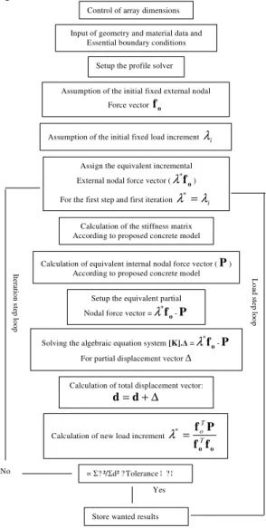
for plane concrete [4] is implemented into the integral sampling points (Gaussian points) defined within the elements through a 3D finite elements technique[5], the resulted numerical model [6] systematically would be able to consider the compressive size effect of plane concrete in analysis. In fact, when the proposed micro-plane damage based model [4] is distributed in three dimensional spaces through the whole body of the concrete specimen by means of integral sampling points of the finite elements [5], the obtained mathematical model [6] would be able to predict precisely the fracture mechanism ( fracture path) and consequently the compressive size effect of concrete specimen. The flowchart of proposed solution procedure is depicted in Fig 1.
Control of array dimensions
Input of geometry and material data and Essential boundary conditions
Setup the profile solver
Calculation of the stiffness matrix According to proposed concrete model
Assign the equivalent incremental
External nodal force vector (λ*fo) For the first step and first iteration λ =* λi
Calculation of equivalent internal nodal force vector (P) According to proposed concrete model
Setup the equivalent partial
Nodal force vector =λ*fo-P Solving the algebraic equation system [K]. =λ*fo-P
For partial displacement vector
Calculation of total displacement vector:
∆ + =d d
Store wanted results Yes No Ite ra tio n s te p lo o p L o ad s te p lo o p
Assumption of the initial fixed external nodal
Force vector fo
Assumption of the initial fixed load increment λi
Calculation of new load increment
o of f P f T T o = * λ
= ? ²/ d² ? Tolerance ¦ ? ¦
Fig. 1: Flowchart of solution procedure of proposed model
SCI-PUBLICATIONS
Author Manuscrip
Am. J. Applied Sci., 5 (2): 106-109, 2008
108
RESULTS AND DISCUSSION
As it was mentioned in introduction of this paper, to study the capability of presented numerical model in assess of compressive size effect of plane concrete, two different sizes of cubic concrete specimens are modeled with proposed software under the uniaxial compressive test and their
726 elements and 1008 nodes
2404 elements and 3600 nodes
Gauss point number 20330 Crack starting point
y x z
Fig. 2: Finite elements meshes and fracture mechanisms
Fracture mechanisms, pre-peak and post-peak strain-stress paths are investigated. Figure 2 shows the finite elements meshes and fracture mechanisms of the two specimens under uniaxial compressive test. The required model material specifications of two specimens are chosen so as to be the same: The elastic modulus and poison's ratio of two specimens are 30000 MPa and 0.18 respectively. Also, the boundary conditions in the specimens are the same: top and bottom of the specimens are both fixed.
Fig. 3: Mean strain – stress curves
As it can be seen from Fig. 2, the fracture mechanisms (fracture paths) of the specimens are different and are dependent of the specimens’ sizes. The fracture type of
the more height specimen is more brittle and fracture energy release rate of it is smaller. This phenomenon can be observed in Fig. 3. In this figure, the obtained average axial strain – stress curves of two specimens are shown. It can be derived from this picture that the smaller specimen behaves more ductility under compressive load. The descending branch mean strain/stress curve of larger specimen is steeper. Figure 3 show that the experimental evidences support the obtained numerical results.
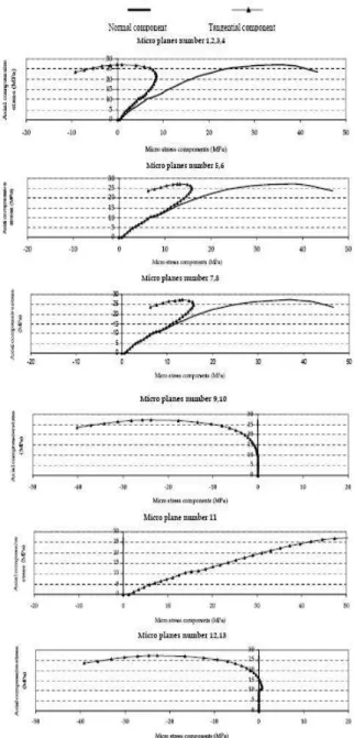
Fig. 4: Micro-stress paths on micro-planes of Gauss point number 20330
SCI-PUBLICATIONS
Author Manuscrip
Am. J. Applied Sci., 5 (2): 106-109, 2008
109 Fig. 5: position of micro-planes in Gauss points
Moreover, as a typical important point, the obtained micro-stress paths on the micro-planes of crack starting point in larger specimen are depicted in Fig. 4. It is introduced from this figure that the reason of fracturing of cubic specimens under uniaxial compressive test is reduction of compressive and increase of shear stress on planes which are positioned about 45 degrees from axial compressive load direction. Position of micro-planes is shown in Fig. 5.
CONCLUSION
By combination of authors’ recently proposed micro-planes damage based model [4] and a 3D finite elements technique [5] creates a powerful numerical software [6] to capture and predict precisely strain localization and fracture mechanism in the specimens and consequently to assess properly the compressive size effect of plane concrete.
For the concrete specimens with the same cross sectional area, as the height of the specimen increases, the fracture mechanism of the specimen becomes more brittle and the fracture energy release decreases.
Obtained numerical results shows that reason of fracturing of cubic specimens under uniaxial compressive test is the reduction of compressive and increase of shear stresses on planes which are positioned about 45 degrees from axial compressive load direction.
REFFERENCES
1. Bazant, Z. P., 1984. Size effect in blunt fracture; concrete, rock, metal. Journal of Engineering Mechanics, American Scociety of Civil Engineering, 110: 518-535
2. Bazant, Z. P. and Y., Xi, 1991. Statistical size effect in quasi-brittle structures: II. Nonlocal theory. Journal of Engineering Mechanics, American Scociety of Civil Engineering, 117: 2623-2640
3. Bazant, Z. P. and Y., Xiang, 1997. Size effect in compression fracture: Splitting crack band propagation. Journal of Engineering Mechanics, American Scociety of Civil Engineering, 123: 162-172
4. Labibzadeh, M. and S.A. Sadrnejad, 2006. Mesoscopic damage based model for plane concrete under static and dynamic loadings. American Journal of Applied Sciences, 3 (9): 2011-2019
5. Labibzadeh, M. and S.A. Sadrnejad, 2006. Dynamic solution code for structural analysis upon joint element. Journal of Computer Sciences, 2 (5): 401-409
6. Labibzadeh, M. and S.A. Sadrnejad, 2007. Crack analysis of concrete arch dams using micro-planes damage based constitutive relations. American Journal of Applied Sciences, 4 (4): 197-202.