AMTD
8, 9009–9044, 2015Preliminary validation of refractivity from a new radio occultation
sounder
M. Liao et al.
Title Page
Abstract Introduction
Conclusions References
Tables Figures
◭ ◮
◭ ◮
Back Close
Full Screen / Esc
Printer-friendly Version
Interactive Discussion
Discussion
P
a
per
|
Discussion
P
a
per
|
Discussion
P
a
per
|
Discussion
P
a
per
|
Atmos. Meas. Tech. Discuss., 8, 9009–9044, 2015 www.atmos-meas-tech-discuss.net/8/9009/2015/ doi:10.5194/amtd-8-9009-2015
© Author(s) 2015. CC Attribution 3.0 License.
This discussion paper is/has been under review for the journal Atmospheric Measurement Techniques (AMT). Please refer to the corresponding final paper in AMT if available.
Preliminary validation of refractivity from
a new radio occultation sounder
GNOS/FY-3C
M. Liao1,2,3, P. Zhang3, G. L. Yang3, Y. M. Bi3, Y. Liu2, W. H. Bai4, X. G. Meng4, Q. F. Du4, and Y. Q. Sun4
1
Nanjing University of Information Science & Technology, Nanjing, China
2
Chinese Academy of Meteorological Sciences, Beijing, China
3
National Satellite Meteorological Center, Beijing, China
4
Center for Space Science and Applied Research, Chinese Academy of Sciences, Beijing, China
Received: 5 May 2015 – Accepted: 29 July 2015 – Published: 1 September 2015 Correspondence to: P. Zhang ([email protected])
AMTD
8, 9009–9044, 2015Preliminary validation of refractivity from a new radio occultation
sounder
M. Liao et al.
Title Page
Abstract Introduction
Conclusions References
Tables Figures
◭ ◮
◭ ◮
Back Close
Full Screen / Esc
Printer-friendly Version
Interactive Discussion
Discussion
P
a
per
|
Discussion
P
a
per
|
Discussion
P
a
per
|
Discussion
P
a
per
|
Abstract
As a new member of space-based radio occultation sounder, the GNOS (Global Navi-gation Satellite System Occultation Sounder) mounted on FY-3C has been carrying out the atmospheric sounding since 23 September 2013. GNOS takes a daily measure-ment up to 800 times with GPS (Global Position System) and Chinese BDS (BeiDou
5
navigation satellite) signals. The refractivity profiles from GNOS are compared with the co-located ECMWF (European Centre for Medium-Range Weather Forecasts) analy-ses in this paper. Bias and standard deviation have being calculated as the function of altitude. The mean bias is about 0.2 % from the near surface to 35 km. The average standard deviation is within 2 % while it is down to about 1 % in the range 5–30 km
10
where best soundings are usually made. To evaluate the performance of GNOS, COS-MIC (Constellation Observing System for Meteorology, Ionosphere and Climate) and GRAS/METOP-A (GNSS Receiver for Atmospheric Sounding) data are also compared to ECMWF analyses as the reference. The results show that GNOS/FY-3C meets the requirements of the design well. It possesses a sounding capability similar to COSMIC
15
and GRAS in the vertical range of 0–30 km, though it needs improvement in higher altitude. Generally, it provides a new data source for global NWP (numerical weather prediction) community.
1 Introduction
When a ray transmitted by GNSS (Global Navigation Satellite System) passes though
20
the atmosphere, the signal received by the GNSS receiver on the LEO (low Earth orbit) satellite will be bent and delayed. The GNSS receiver records the bending and delay information in terms of amplitude and phase, which is related to the physical conditions of the atmosphere (Kursinski et al., 1996). The atmosphere sounding by the RO (radio occultation) technology was proposed by Fishbach (1965) and Lusignan et al. (1969).
25
AMTD
8, 9009–9044, 2015Preliminary validation of refractivity from a new radio occultation
sounder
M. Liao et al.
Title Page
Abstract Introduction
Conclusions References
Tables Figures
◭ ◮
◭ ◮
Back Close
Full Screen / Esc
Printer-friendly Version
Interactive Discussion
Discussion
P
a
per
|
Discussion
P
a
per
|
Discussion
P
a
per
|
Discussion
P
a
per
|
1997; Rocken et al., 1997). With the advantages of high vertical resolution, high accu-racy, all-weather sounding, free of calibration, long-term constant and global coverage, radio occultation missions were continuously carried out, such as CHAMP (CHAlleng-ing Minisatellite Payload), SAC-C (Satellite de Aplicaciones Cientificas – C), COSMIC, GRAS/METOP, etc. The data from these missions are used widely in the field of NWP
5
(nuclear weather prediction) (Hajj et al., 2004; Kuo et al., 2000) and climate change (Anthes, 2011). The ROs data are used for space weather monitoring as well (Yue et al., 2011). China has been developing the space-based RO technology since the 2000s (Yang et al., 2012). The first satellite-based RO instrument named GNOS (Global Nav-igation Satellite System Occultation Sounder) was launched on 23 September 2013
10
and mounted on the Chinese polar orbiting meteorological satellite FY-3C (Bai et al., 2014).
The refractivity profile is the elementary product from the RO sounding. The high level products, such as density, temperature and humidity profiles will be retrieved from the refractivity. Meanwhile, the refractivity is the parameter which will be assimilated
15
into NWP model directly (Anthes et al., 2000). There has been a lot of work done to demonstrate the accuracy of the ROs data, especially the refractivity (Kursinski et al., 1996; Rocken et al., 1997; Hajj et al., 2002, 2004; Poli et al., 2003). Kuo et al. (2005) pointed out that the most accurate ROs data are at the altitudes from 5 to 25 km and the data can be used as the reference to assess the performance of the
20
current radiosonde. W. Schreiner (2007) estimated the precision of the refractivity from COSMIC/FORMOSAT-3 mission. His work shows that the RMS difference is less than 0.2 % from 10 to 20 km altitude. With the pre-launch proxy data, Bi et al. (2012) in-vestigate the possible accuracy of the refractivity profiles from GNOS. The simulated results show the high accuracy of the refractivity from the GNOS occultation in the
tro-25
fam-AMTD
8, 9009–9044, 2015Preliminary validation of refractivity from a new radio occultation
sounder
M. Liao et al.
Title Page
Abstract Introduction
Conclusions References
Tables Figures
◭ ◮
◭ ◮
Back Close
Full Screen / Esc
Printer-friendly Version
Interactive Discussion
Discussion
P
a
per
|
Discussion
P
a
per
|
Discussion
P
a
per
|
Discussion
P
a
per
|
ily, the post-launch performance of GNOS is critical to the user community. This paper focused on the validation of the refractivity from the GNOS measurements. GNOS can carry out RO from both GPS and Chinese BDS signals. GPS is the full developed sys-tem, while Chinese BDS is still in development. In order to compare, both GNOS GPS refractivity and GNOS BDS refractivity are validated with co-located ECMWF analyses
5
in this work. The paper is designed as follows: Sect. 2 briefly describes the processes of GNOS; Sect. 3 introduces the data used for the validation; Sect. 4 presents the results of the validation, and the conclusion is presented in the last part.
2 Overview of GNOS data
GNOS is mounted on the Chinese FY-3C meteorological satellite. Fengyun 3 (FY-3)
10
is the second generation polar orbiting satellite in Chinese meteorological series. The first two satellites of FY-3, i.e., FY-3A and FY-3B, are nominated as the research and development mission. Therefore, FY-3C is the first satellite in operation for FY-3 se-ries (Yang et al., 2012). According to satellite programme, GNOS will be mounted on FY-3C and the follow-ups. It expected that GNOS on FY-3 series will provide the RO
15
measurement consistently at least until 2030.
GNOS is a multi-GNSS receiver, which has the ability of tracking up to eight GPS satellites and four BDS satellites for precise orbit determination, respectively. In addi-tion, it has velocity and anti-velocity antennas for simultaneously tracking at most six and four occultations from GPS and BDS, respectively. The more information for GNOS
20
instrument specification can be found in Bai et al. (2014).
2.1 Data processing
The operational procedure of the GNOS data in the ground segment is described briefly in this section. There are five steps mainly from the raw GNOS data to the retrieved atmospheric parameters.
AMTD
8, 9009–9044, 2015Preliminary validation of refractivity from a new radio occultation
sounder
M. Liao et al.
Title Page
Abstract Introduction
Conclusions References
Tables Figures
◭ ◮
◭ ◮
Back Close
Full Screen / Esc
Printer-friendly Version
Interactive Discussion
Discussion
P
a
per
|
Discussion
P
a
per
|
Discussion
P
a
per
|
Discussion
P
a
per
|
2.1.1 Data preparation
The raw observations of GNOS contain phase and SNR (signal to noise ratio) mea-surements. Besides the raw observation, other affiliated information provided by IGS (International GNSS Service) is also needed, such as GPS/BDS precise orbits, clock files, the Earth orientation parameters, coordinates and velocities of the ground
sta-5
tions. The IGS ultra rapid orbit products with about 10 cm accuracy in orbit are chosen for near-real-time operational use.
2.1.2 Precise orbit determination
High accuracy of time and position of the GNSS and LEO are the keys to the successful retrieval for an occultation event. Regarding the pseudo range, carrier phase data and
10
attitude information of GNOS POD (precise orbit determination) antenna, the GNSS clock offsets, precise orbit and Earth orientation parameters, LEO POD is conducted by integrating the equations of celestial motion (Beutler, 2005), using the Bernese soft-ware v5.0. At length, precise orbit products with an orbit accuracy of∼20 cm can be
produced in near-real time.
15
2.1.3 Excess phase calculation
Single difference technique is applied to obtain the excess phase as a function of time in an Earth centered inertial (ECI) reference frame. When GNOS receives signals from an occulting GNSS satellite, it receives the signals from a reference GNSS satellite at the same time. With such reference observation mode, all clock errors can be removed
20
AMTD
8, 9009–9044, 2015Preliminary validation of refractivity from a new radio occultation
sounder
M. Liao et al.
Title Page
Abstract Introduction
Conclusions References
Tables Figures
◭ ◮
◭ ◮
Back Close
Full Screen / Esc
Printer-friendly Version
Interactive Discussion
Discussion
P
a
per
|
Discussion
P
a
per
|
Discussion
P
a
per
|
Discussion
P
a
per
|
require a reference satellite for simultaneous observations but requires an ultra-stable oscillator on LEO receiver (Beyerle et al., 2005).
2.1.4 Atmospheric parameter retrieval
From excess phase to atmospheric parameters, the Radio Occultation Processing Package (ROPP) software (V6.0) developed at GRAS SAF (Satellite Application
Fa-5
cility) is used to determine different kinds of atmospheric parameters (Offiler, 2008). The bending angle can be obtained through the geometric relationship of GNSS and LEO, with the input parameters like excess phase, Doppler drift and velocities. As to GNOS, the geometric optics approximation is set above 25 km. While below 25 km, there are obvious and complicated multipath effects (Sokolovskiy et al., 2003).
There-10
fore, wave optics (also referred to as the canonical transform algorithm) developed by Gorbunov (2004) are used below 25 km. From bending angle to refractivity, in or-der to obtain the neutral atmospheric refractivity, the ionospheric contribution must be removed. As the neutral atmosphere is independent of GNSS frequencies but iono-sphere is not, a simple linear combination can mostly correct for ionospheric
contribu-15
tion (Vorob’ev and Krasil’nikova, 1994). This can be done using two frequencies (f1,f2) and corresponding bending angles (α1,α2), a function of impact parameter (a) (Eq. 1).
α(a)=f 2
1α1(a)−f22α2(a) f12−f22
(1)
In addition to that, statistical optimization devised by Gorbunov (2002) is used for ionospheric residuals with MSISE-90 climatology model (Hedin, 1991) to reduce the
20
noise above 50 km. The optimal linear combination is expressed as a matrix equation to compute the neutral atmospheric bending angle and ionospheric bending angle.
AMTD
8, 9009–9044, 2015Preliminary validation of refractivity from a new radio occultation
sounder
M. Liao et al.
Title Page
Abstract Introduction
Conclusions References
Tables Figures
◭ ◮
◭ ◮
Back Close
Full Screen / Esc
Printer-friendly Version
Interactive Discussion
Discussion
P
a
per
|
Discussion
P
a
per
|
Discussion
P
a
per
|
Discussion
P
a
per
|
1997), and then refractivityN can be obtained from the refractive indexn(Eq. 3).
n(r)=exp[1 π
∞ Z
x
α(a) p
a2−x2
da] (2)
N=(n−1)×106 (3)
Due to moisture ambiguity in the lower troposphere, temperature and humidity pro-files could not be interpreted simultaneously from refractivity (Poli et al., 2002).
There-5
fore, one-dimensional variational (1-D-Var) analysis combined with the background in-formation from the T639 forecast model is used to retrieve temperature and humidity profiles.
2.1.5 Quality control
From raw data to atmospheric parameters, there are several simple quality controls with
10
respect to each stage. If the occultation time is less than 30 s or the SNR smaller than 40, the occultation profile will be rejected; if the lowest tangent height of L2 frequency does not reach below 20 km, the occultation profile will be flagged; if the bending angle is greater than 0.06 rad, the profile will be rejected; if the absolute temperature dif-ference from the analysis is greater than 10 K, the profile also can not be produced.
15
Figure 1a and b are the daily numbers of occultation from the beginning of the events to temperature profiles after correspondent stages of quality control for GNOS GPS and GNOS BDS, respectively. This is the status of 15 days since 3 October 2013. The different colors indicate different stages: the blue denotes the number of raw obser-vations; the red denotes the number of excess phase profiles; the green one is the
20
number of refractivity profiles; and the purple is the number of temperature profiles, as a result of corresponding stages of quality control. From the raw observations to excess phase,∼10 % (∼13 %) GNOS GPS (BDS) observations are excluded. After the
AMTD
8, 9009–9044, 2015Preliminary validation of refractivity from a new radio occultation
sounder
M. Liao et al.
Title Page
Abstract Introduction
Conclusions References
Tables Figures
◭ ◮
◭ ◮
Back Close
Full Screen / Esc
Printer-friendly Version
Interactive Discussion
Discussion
P
a
per
|
Discussion
P
a
per
|
Discussion
P
a
per
|
Discussion
P
a
per
|
will be excluded.∼7 % (∼6 %) GNOS GPS (BDS) will be rejected during the process
of refractivity to temperature.
2.2 The status of the GNOS products
Through the above processing, both GNOS GPS and GNOS BDS products are gen-erated in the very similar way. Nevertheless, slight differences exist because BDS B1
5
has not implemented open-loop tracking. There is no open-loop tracking data process-ing for B1. While GPS L1 operates below 10 km with 100 Hz samplprocess-ing rates (Bai et al., 2014). Another difference is that B1 and B2 are both open to civil use and anti-spoofing (AS) is off. Therefore, B2 does not go through semi-codeless technology like GPS L2, ensuring that dual-frequency retrievals can be done in its valid tracking height range.
10
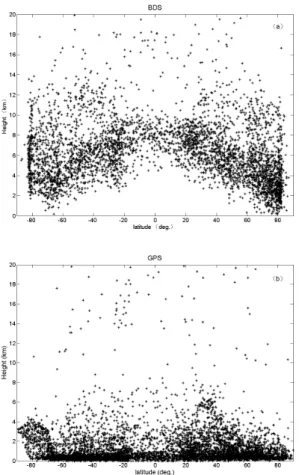
Open-loop tracking is aiming to detect significant fluctuation of RO signals, after they pass through the moist lower troposphere, without the use of feedback. It could re-duce errors and loss of lock, which closed-loop fails to do (Sokolovskiy et al., 2001). With open-loop tracking, more profiles will be reached at lower altitude (Ao et al., 2009). This can be demonstrated by the different penetration depths between GNOS BDS and
15
GNOS GPS. Figure 2a shows that GNOS BDS stops mostly above 2 km. In the tropical area, the penetration depth reaches even higher, almost above 5 km. while GNOS GPS with open-loop tracking can reach below 1 km (Figs. 2b and 3). Figure 3 is an exam-ple of the accumulation of GPS occultation, showing the locations and lowest altitude reached. There are more than 68 000 profiles with the global coverage from 1 January
20
to 30 May 2014. Occultation spots are almost evenly distributed, while the mid and high latitude zones spread more densely than at low latitude. The lowest altitude penetrated in the atmosphere can be reached below 2 km in the majority of cases, except for the higher-lying areas, and there are about 90 % of the soundings within 1 km of the Earth’s surface. This penetration is comparable to the GPS occultation.
25
AMTD
8, 9009–9044, 2015Preliminary validation of refractivity from a new radio occultation
sounder
M. Liao et al.
Title Page
Abstract Introduction
Conclusions References
Tables Figures
◭ ◮
◭ ◮
Back Close
Full Screen / Esc
Printer-friendly Version
Interactive Discussion
Discussion
P
a
per
|
Discussion
P
a
per
|
Discussion
P
a
per
|
Discussion
P
a
per
|
NSMC. At present, only GNOS GPS products are open to community through the website (http://fy3.satellite.cma.gov.cn/PortalSite/Data/DataView.aspx?SatelliteType= 0&DataCategoryCode=L1&InstrumentTypeCode=GNOS). The GNOS BDS products are still under the evaluation phase and are not in the operational stream for the public.
3 Data and method for validation
5
3.1 Data
The refractivity profiles in this paper come from three sources. And the reanalysis field data are from ECMWF. The detailed information is described below:
The first source is the GNOS. Specifically, GNOS GPS refractivity is obtained from the operational stream, while GNOS BDS is obtained from the experiment system
10
as it does not become operational. The second one is COSMIC, which is obtained from CDAAC (COSMIC Data Analysis and Archive Center, Boulder, USA), naming cosmic2013 (http://cdaac-www.cosmic.ucar.edu/cdaac/products.html). The third one is METOP-A/GRAS obtained also from CDAAC. The reason for selecting COSMIC and GRAS data is that they can be taken as benchmarks to GNOS, since they are the
15
identical types of occultation sounders. The last reference data are the ERA-Interim reanalysis. ERA-Interim is the latest global atmospheric reanalysis produced by the European Centre for Medium-Range Weather Forecasts (ECMWF) (Dee et al., 2011), hereafter called ECMWF analyses. The spatial resolution of the data set is approxi-mately 80 km (T255 spectral) on 60 vertical levels from the surface up to 1 hPa.
20
In addition to that, raw bending angles of GNOS GPS and GRAS coincident pairs are also applied to analyze the performance of GNOS.
AMTD
8, 9009–9044, 2015Preliminary validation of refractivity from a new radio occultation
sounder
M. Liao et al.
Title Page
Abstract Introduction
Conclusions References
Tables Figures
◭ ◮
◭ ◮
Back Close
Full Screen / Esc
Printer-friendly Version
Interactive Discussion
Discussion
P
a
per
|
Discussion
P
a
per
|
Discussion
P
a
per
|
Discussion
P
a
per
|
3.2 Method
First is the spatial match. The ECMWF analyses and ROs are matched within±3 h time interval. The ECMWF analyses of temperature, water vapor pressure and pressure profiles with 0.75×0.75◦degree are bi-linearly interpolated to the longitude and latitude
of ROs. And then with parameters in terms of temperature (T), water vapor pressure
5
(e) and air pressure (P), analysis profiles are calculated into refractivity (N) using the formula (Eq. 4) without the ionospheric effects (Kursinski et al., 1997; Rocken et al., 1997).
N=77.6P
T +3.73×10 5 e
T2 (4)
Thirdly, both the forwarded refractivity and the co-located observational refractivity
10
are vertically logarithm interpolated to the same altitude at 200 m interval from 0–50 km. Thus, fractional refractivityδN is computed from those prepared profiles to show the relative error between ECMWF analyses and ROs (Eq. 5).
δN=(Ngnss−NECMWF)
NECMWF ×100 % (5)
Therefore, there are four pairs of ECMWF analyses and ROs in terms of fractional
15
refractivity: GNOS GPS to ECMWF pairs, GNOS BDS to ECMWF pairs, COSMIC to ECMWF pairs and GRAS to ECMWF pairs.
At last, the bias and standard deviation of each pair will be obtained through statis-tics. Besides the quality controls at different stages of processes, extra quality controls are applied during the process of statistics. If the fractional refractivity is greater than
20
AMTD
8, 9009–9044, 2015Preliminary validation of refractivity from a new radio occultation
sounder
M. Liao et al.
Title Page
Abstract Introduction
Conclusions References
Tables Figures
◭ ◮
◭ ◮
Back Close
Full Screen / Esc
Printer-friendly Version
Interactive Discussion
Discussion
P
a
per
|
Discussion
P
a
per
|
Discussion
P
a
per
|
Discussion
P
a
per
|
4 Validation results and discussions
4.1 Comparison with ECMWF
4.1.1 GNOS vs. ECMWF
To quantify the error characteristics, Fig. 4 is the result of the statistical comparison be-tween GNOS GPS and ECMWF analysis. It shows that the mean fractional refractivity
5
is very close to zero, exhibiting good agreement with ECMWF analyses and reconfirm-ing the bias-free characteristic of radio occulation. Below the height of 2 km, it slightly demonstrates negative bias ∼1 %, which is related to multipath effect due to super-refractivity (Sokolovskiy et al., 2003, 2009). From 5 to 30 km, little bias is shown, about
−0.09 %, performing rather well. Above 45 km, the negative bias gets about−0.05 %.
10
We notice the pair samples are steadily reduced above 43 km, which is consistent with the region of negative bias. The reason the number of pairs decrease is that the ECMWF analyses we used only contain 60 levels, and the top altitude is about 46 km. When we interpolated the ECMWF analyses into 200 m intervals from 0 to 50 km, there will be some gap between 50 km and the actual height of ECMWF analysis. Therefore,
15
the available pairs at high latitude will decrease.
As to standard deviation, the highest accuracy is from 5 to 30 km, smaller than 1 %. This is consistent with the results of previous validations for RO data (Kuo et al., 2004; von Engeln et al., 2009). Up to the height of 35 km, the standard deviation is still within 2 %. While above 35 km, the standard deviation starts to increase with height. This
20
attributes to either the analysis or the occultation observations. Mainly, as to the occul-tation, uncalibrated ionospheric effects are one kind of observational noise source, and the use of supplementary data, for noise reduction through an optimization procedure, is also introducing errors (Kuo et al., 2004).
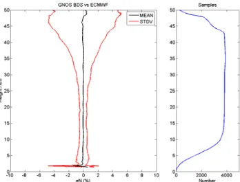
Figure 5 demonstrates the result of GNOS BDS. The mean deviation in the altitude
25
range of 0–50 km is approximately−0.02 %, showing less negative than GNOS GPS.
AMTD
8, 9009–9044, 2015Preliminary validation of refractivity from a new radio occultation
sounder
M. Liao et al.
Title Page
Abstract Introduction
Conclusions References
Tables Figures
◭ ◮
◭ ◮
Back Close
Full Screen / Esc
Printer-friendly Version
Interactive Discussion
Discussion
P
a
per
|
Discussion
P
a
per
|
Discussion
P
a
per
|
Discussion
P
a
per
|
deviation tends to be about 0.71 %. This shows better performance than GNOS GPS. We attribute this to the B2. As mentioned in the part 2, the frequencies of B1 and B2 are both coarse code and open to civil use. The anti-spoofing for B2 is off, and there is no need to use the semi-codeless method. Therefore, the ionospheric effect could be removed more efficiently when combining the two frequencies. Nevertheless,
5
it should be noted that the “good” performance of BDS below 5 km may be an illusory phenomenon. The sample size on the right panel of Fig. 5 shows it reduced rapidly below 5 km. As GNOS BDS is still using closed-loop tracking, most of the signal stops above 4 km. This results in fewer valid pairs for statistics and possibly bringing some representativeness error. The penetration depth of BDS can be referred to Fig. 2a.
10
4.1.2 GNOS, COSMIC and GRAS vs ECMWF
In order to better evaluate the performance of GNOS, the COSMIC and GRAS data are also compared with ECMWF, taking as a benchmark to GNOS. Figure 6 provides the mean (on the left panel) and standard deviation (on the right panel) of the ROs to ECMWF. Including GNOS GPS with green line, GNOS BDS with blue line, COSMIC
15
with red line and GRAS with black line. The values of the refractivity noise in Fig. 6 are presented in Table 1.
From the near surface to 40 km altitude, the fluctuant features of ROs vs. altitude coincide with each other very well, showing that GNOS performs similarly with GRAS and COSMIC in terms of mean bias. As to the standard deviation, GNOS, COSMIC
20
and GRAS are consistent below 30 km. The magnitudes of the fractional refractivity of GNOS GPS and GNOS BDS are both within 2 % up to 35 km. And their average values from 0 to 40 km are∼0.93 and∼0.71 %, respectively, meeting the design requirement.
As seen in previous studies, the radio-occultation-data spreads from the middle tropo-sphere to the lower stratotropo-sphere play a key role in numeric weather prediction (Kuo
25
AMTD
8, 9009–9044, 2015Preliminary validation of refractivity from a new radio occultation
sounder
M. Liao et al.
Title Page
Abstract Introduction
Conclusions References
Tables Figures
◭ ◮
◭ ◮
Back Close
Full Screen / Esc
Printer-friendly Version
Interactive Discussion
Discussion
P
a
per
|
Discussion
P
a
per
|
Discussion
P
a
per
|
Discussion
P
a
per
|
30 km. The source of the error is not yet well understood. Based on some hypotheses, various factors may contribute to it. We think this discrepancy from the data-processing algorithm rather than from the instrument observation noise. COSMIC and GRAS re-fractivity products are from the CDACC. The data-processing algorithm and initial data set for COSMIC and GRAS are in the same baseline while for GNOS are not. For
ex-5
ample, in order to save time, we only use 20 ground stations for the calculation of GPS clock offset, and the POD was computed based on a 6 h data arcs. While COSMIC uses at least 32 stations and based on a 6–12 h data arcs. Typically, the more stations data used and the longer data arcs are computed, the higher accuracy of retrievals. It is one important direction that the GNOS data processing should be improved. In
ad-10
dition, any cycle slips that evade detection will contaminate the retrieval. The Doppler biases of GNOS, just as the result of the simulation study by Bi et al. (2012), may in-troduce about 0.5 % noise at 40 km. Besides, structural uncertainty exists. We know that ECMWF analysis is a compound of various data source including radio occulta-tion, such as GRAS and COSMIC, but it does not include GNOS. Therefore, GNOS
15
and ECMWF are totally independent; if any difference exists, it might be greater than GRAS and COSMIC under certain conditions. The other difference is that the data of GNOS currently is obtained from NRT stream, and the POD is conducted with ultra-rapid IGS orbits products. COSMIC2013 and GRAS from CDAAC are post-processed with higher precision. GNOS presents larger standard deviations above 30 km, which
20
is likely caused by the data processing as well, probably indicating that less smoothing is used in GNOS.
Anyway, further studies will be carried out to find out what exactly contributes to the random error at upper height. Overall, the accuracy of GNOS is promising from 5 to 30 km.
25
4.2 Cross comparison between GNOS GPS and GRAS
AMTD
8, 9009–9044, 2015Preliminary validation of refractivity from a new radio occultation
sounder
M. Liao et al.
Title Page
Abstract Introduction
Conclusions References
Tables Figures
◭ ◮
◭ ◮
Back Close
Full Screen / Esc
Printer-friendly Version
Interactive Discussion
Discussion
P
a
per
|
Discussion
P
a
per
|
Discussion
P
a
per
|
Discussion
P
a
per
|
the polar orbits with the altitudes of 836 km (FY-3C) and 817 km (METOPA); they are subject to comparable geopotential and atmospheric drag, and they both receive GPS signal. However, their comparisons are still strict to different viewing geometries, result-ing in different atmospheric and ionospheric propagation. Hajj et al. (2004) proposed a comparison for coincident occultations under the condition that the time is within 1/2 h
5
and the distance is 200 km apart. For more data samples, we limit the time within 3 h, and the distance less than 200 km. The distance is defined as the distance of tangent heights between two occultations at 30 km (this means that some point pairs may be larger than 200 km). For the period 1 October to 31 December 2013, there are∼40 000
GNOS GPS and∼54 000 GRAS occultations to build 2094 coincident pairs set.
10
Figure 7 demonstrates the histograms of fractional bending angle differences of GNOS GPS and GRAS for the three altitude intervals. It can show the distribution of relative errors between GNOS GPS and GRAS. We found that the fractional bend-ing angle differences exhibit similar distributions at the impact height of 20–40 and 0–20 km, both mainly focus on the range of ±0.05 and with a narrow shape. While
15
on the higher level, the fractional bending angle shows wider spectrum, demonstrating larger discrepancy. It should not be excluded that the systematic representative error due to time and space gaps.
Then we further look into the altitude of 40–60 km, analyzing the absolute differences between GNOS GPS and GRAS. Figure 8 is the statistics result of GNOS GPS and
20
GRAS at the impact height of 30–60 km. The MEAN indicates the average difference of GNOS GPS deviation from GRAS vs. impact height, while the STDV indicates the standard deviation between GNOS GPS and GRAS. For their calculation, we remove the collocated pairs with |GNOS GRAS| > 10 µrad by considering them to be outliners. Those outliners give a proportion of∼20 %. As the figure shown below, the average
25
of the mean difference is approximately−7.2×10⁻⁸rad, and the standard deviation is
AMTD
8, 9009–9044, 2015Preliminary validation of refractivity from a new radio occultation
sounder
M. Liao et al.
Title Page
Abstract Introduction
Conclusions References
Tables Figures
◭ ◮
◭ ◮
Back Close
Full Screen / Esc
Printer-friendly Version
Interactive Discussion
Discussion
P
a
per
|
Discussion
P
a
per
|
Discussion
P
a
per
|
Discussion
P
a
per
|
the main contribution of the error at high altitude may come from the outliners. We set time intervals as ±2, ±1 or±0.5 h between GNOS GPS and GRAS, finding that the outliners are not sensitive to it. As the analyses are based on the non-optimal statis-tical bending angles, the residuals related to ancillary data (MSIS model climatology) through optimization procedure are probably not the main source; the main source
5
is probably the previous data processing. In addition, the occultation antenna gain of GNOS in azimuth is approximately 10 dBi in the range of ±35◦. Compared with ±55◦
GRAS, this probably results in fewer occultations and lower SNR for GNOS, espe-cially in the weak signal region. This could aid in interpreting the discrepancy between GNOS GPS and GRAS in terms of refractivity in Sect. 4.1.2. Nevertheless, this issue
10
is currently under investigation.
4.3 The performance in lower troposphere with and without open-loop tracking
An occultation event occurs when a GNSS satellite rises or sets and the ray path from the GNSS transmitter traverse the Earth’s atmosphere (Kursinski et al., 1997). The tracking of rising occultations once was a challenge, as it starts from the lower
tropo-15
sphere with a low SNR (Ao et al., 2009). After the open-loop tracking was implemented, the tracking ability for rising occultation is much improved (Ao et al., 2009). We know that GNOS GPS uses open-loop tracking, but GNOS BDS does not. In this section, we will examine their respective differences in performance in the lower troposphere.
Figure 9 is shows the fractional refractivity deviation from ECMWF analysis, for the
20
rising and the setting occultations of GNOS GPS and GNOS BDS in the lower tro-posphere. In the right panel of each subplot, it is the number of samples vs. altitude. From the statistical results of the rising occultation and the setting occultation of GNOS GPS, the mean and standard deviation in the lower troposphere are similar, only with a slightly bigger negative bias below 2 km. This demonstrates that the rising
occulta-25
tion has the same ability to track the signal in the lower troposphere, after implement-ing open-loop trackimplement-ing. The standard deviation of the risimplement-ing and settimplement-ing differs up to
iden-AMTD
8, 9009–9044, 2015Preliminary validation of refractivity from a new radio occultation
sounder
M. Liao et al.
Title Page
Abstract Introduction
Conclusions References
Tables Figures
◭ ◮
◭ ◮
Back Close
Full Screen / Esc
Printer-friendly Version
Interactive Discussion
Discussion
P
a
per
|
Discussion
P
a
per
|
Discussion
P
a
per
|
Discussion
P
a
per
|
tical with the result of Zus et al. (2011), which using the GRAS refractivity and ECMWF analysis. Also note that the setting occultations get more valid data points than the rising occultations below the lower troposphere. That is because there are more data gaps in the rising occultation of the closed-loop part, and those discontinuous records are rejected by the quality control during the retrieval process.
5
While as to GNOS BDS, obviously, the penetration depths of the rising and setting occultations are both higher than the depths of GNOS GPS, especially in the rising occultation, whose valid height stops at 4 km. Besides, below the altitude of 5 km, the biases of the rising and setting occulations from GNOS BDS are both larger than those from GNOS GPS. These mainly attribute to the non-implementation of open-loop
track-10
ing for GNOS BDS. This once again gives us evidence that the open-loop tracking tech-nique can strongly improve the ability to track the signal into the lower troposphere. Its implementation for GNOS BDS is essential for the next generations.
4.4 The performance in different latitudes and seasons
In this part, we separate GNOS GPS occultations into different latitudes: the
North-15
ern Hemisphere (30–90◦N), the tropics (30◦N–30◦S) and the Southern Hemisphere (30◦S–90◦N). As the orbital characteristics of BDS, including MEO (medium Earth orbit satellites), IGSO (inclined geosynchronous stationary Earth orbit satellites) and GEO (geosynchronous Orbit satellites) (China Satellite Navigation Office, 2012), most of the occultations take place around the Eastern Hemisphere and leave “holes” at the
20
tropics (Fig. 10). Therefore, in order to avoid “representativeness” errors, we only show the result of GNOS GPS.
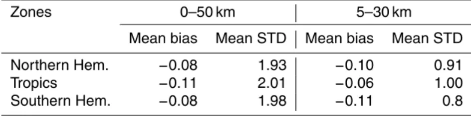
Figure 11 exhibits the statistics results showing that the mean and standard de-viations of fractional refractivity between GNOS GPS and ECMWF analyses in the Northern Hemisphere is straighter than in the tropical area and in the Southern
Hemi-25
AMTD
8, 9009–9044, 2015Preliminary validation of refractivity from a new radio occultation
sounder
M. Liao et al.
Title Page
Abstract Introduction
Conclusions References
Tables Figures
◭ ◮
◭ ◮
Back Close
Full Screen / Esc
Printer-friendly Version
Interactive Discussion
Discussion
P
a
per
|
Discussion
P
a
per
|
Discussion
P
a
per
|
Discussion
P
a
per
|
the southern and Northern Hemisphere. In the tropics, larger negative and positive biases are found in the lower troposphere, with the largest−2 % bias and 4 %
stan-dard deviation. The error characteristics in this zone are expected. The greater bias and standard deviation in the tropics, especially below 5 km, may be related to moist atmosphere, which contributes to the multipath effect (Hajj et al., 2004).
5
These comparisons give evidences to say that radio occultations perform better at middle and high zones. The error fluctuation occurs above 15 km, the height of the top troposphere to low stratosphere. This kind of phenomenon also exists in the GRAS and COSMIC, seeing Fig. 6, showing that the wavy structures are real. Since having high vertical resolution, ROs data could show more vertical details than ECMWF, especially
10
at the height of the tropical cold-point tropopause, and could detect small-scale (<∼
1000 km) oscillations (Alexander et al., 2008).
In addition to different latitudes, we evaluate the fractional refractivity of GNOS GPS deviated from the ECMWF analyses in different seasons (winter and summer). This is based on the data for the month of December 2013 and August 2014. The purpose of
15
the data is to examine the different performance in the cold and dry conditions as well as in the warm and wet conditions. From the result of the former part, the bias of GNOS BDS occultation is sensitive to moist atmosphere without open-looping tracking. Hence, only GNOS GPS occultation is analyzed in terms of seasons. Statistically, the quality of GNOS GPS for the month of December and August is not substantially different from
20
the samples now used (the graph is not shown).
5 Conclusions
The main purpose of this study is to evaluate the post-launch performance of GNOS/FY3C. The operational NRT refractivity product is compared with the ECMWF analysis, the GRAS/METOP and COSMIC products as well. The results show that the
25
AMTD
8, 9009–9044, 2015Preliminary validation of refractivity from a new radio occultation
sounder
M. Liao et al.
Title Page
Abstract Introduction
Conclusions References
Tables Figures
◭ ◮
◭ ◮
Back Close
Full Screen / Esc
Printer-friendly Version
Interactive Discussion
Discussion
P
a
per
|
Discussion
P
a
per
|
Discussion
P
a
per
|
Discussion
P
a
per
|
of 40 km. The results of GRAS/METOP and COSMIC data compared with ECMWF analysis are also presented as the reference. It demonstrated that GNOS/FY-3C per-forms similarly to GRAS/METOP and COSMIC in terms of bias and standard deviation in the range of 0 to 30 km. As to different zones, GNOS GPS can reflect the superiority of middle and high latitude zones over the tropics, due to less multipath propagation in
5
the moist atmosphere especially in the lower troposphere. When separating into set-ting and rising occulted mode for GPS and BDS, there is an obvious discrepancy with and without open-loop tracking for the rising occultations in the lower troposphere. As a new member of space-based RO sounder, GNOS/FY-3C can provide the refractiv-ity profile product to the user communrefractiv-ity with satisfactory accuracy below 30 km. The
10
slightly bigger standard deviation of GNOS exists above 35 km. It shows there is still a lot of work required to improve its performance in the middle and upper stratosphere.
Acknowledgements. The authors are thankful to the CDAAC for providing COSMIC and
METOP-A radio occultation data. Last but not least, we would like to thanks to ECMWF for providing analyses profiles.
15
References
Alexander, S. P., Tsuda, T., Kawatani, Y., and Takahashi, M.: Global distribution of atmospheric waves in the equatorial upper troposphere and lower stratosphere: COSMIC observations of wave mean flow interactions, J. Geophys. Res., 113, D24115, doi:10.1029/2008JD010039, 2008.
20
Anthes, R. A, Rocken, C., and Kuo, Y. H.: Applications of COSMIC to meteorology and climate, Terrestrial Atmospheric and Oceanic Sciences, 11, 115–156, 2000.
Anthes, R. A.: Exploring Earth’s atmosphere with radio occultation: contributions to weather, climate and space weather, Atmos. Meas. Tech., 4, 1077–1103, doi:10.5194/amt-4-1077-2011, 2011.
25
AMTD
8, 9009–9044, 2015Preliminary validation of refractivity from a new radio occultation
sounder
M. Liao et al.
Title Page
Abstract Introduction
Conclusions References
Tables Figures
◭ ◮
◭ ◮
Back Close
Full Screen / Esc
Printer-friendly Version
Interactive Discussion
Discussion
P
a
per
|
Discussion
P
a
per
|
Discussion
P
a
per
|
Discussion
P
a
per
|
Bai, W. H., Sun, Y. Q., Du, Q. F., Yang, G. L., Yang, Z. D., Zhang, P., Bi, Y. M., Wang, X. Y., Cheng, C., and Han, Y.: An introduction to the FY3 GNOS instrument and mountain-top tests, Atmos. Meas. Tech., 7, 1817–1823, doi:10.5194/amt-7-1817-2014, 2014.
Beutler, G.: Methods of Celestial Mechanics, Springer-Verlag, Berlin, Heidelberg, New York, Germany, USA, ISBN 3-211-82364-6, 2005.
5
Beyerle, G., Schmidt, T., Michalak, G., Heise, S., Wickert, J., and Reigber, C.: GPS radio occul-tation with GRACE: Atmospheric profiling utilizing the zero difference technique, Geophys. Res. Lett., 32, L13806, doi:10.1029/2005GL023109,2005.
Bi, Y.-M., Yang, Z.-D., Zhang, P., Sun, Y.-Q., Bai, W.-H., Du, Q.-F., Yang, G. L., Chen, J., and Liao, M.: An introduction to China FY3 radio occultation mission and its measurement
simu-10
lation, J. Adv. Space Res., 49, 1191–1197, doi:10.1016/j.asr.2012.01.014, 2012.
China Satellite Navigation Office: Beidou navigation satellite system signal in space interface control document-open service signal B1I(V 1.0), available at: http://en.beidou.gov.cn/ (last access: 16 June 2014), 2012.
Dee, D. P., Uppala, S. M., Simmons, A. J., Berrisford, P., Poli, P., Kobayashi. S., Andrae, U.,
15
Balmaseda, M. A., Balsamo, G., Bauer, P., Bechtold, P., Beljaars, A. C. M., van de Berg, L., Bidlot, J., Bormann, N., Delsol, C., Dragani, R., Fuentes, M., Geer, A. J., Haimberger, L., Healy, S. B., Hersbach, H., Hólm, E. V., Isaksen, L., Kållberg, P., Köhler, M., Matricardi, M., McNally, A. P., Monge-Sanz, B. M., Morcrette, J.-J., Park, B.-K., Peubey, C., de Ros-nay, P., Tavolato, C., Thépaut, J-N., and Vitart, F.:The ERA-Interim reanalysis: configuration
20
and performance of the data assimilation system, Q. J. Roy. Meteor. Soc., 137, 553–597, doi:10.1002/qj.828, 2011.
Fjeldbo, G., Kliore, G. A., and Eshleman, V. R.: The neutral atmosphere of Venus as studied with the Mariner V radio occultation experiments, Astron. J., 76, 123–140, 1971.
Fishbach, F. F.: A satellite method for temperature and pressure below 24 km, B. Am. Meteorol.
25
Soc., 9, 528–532, 1965.
Hedin, A. E.: Extension of the MSIS thermosphere model into the middle and lower atmosphere, J. Geophys. Res., 96, 1159–1172, 1991.
Gorbunov, M. E.: Ionospheric correction and statistical optimization of radio occultation data, Radio Sci., 37, 17-1–17-9 , doi:10.1029/2000RS002370, 2002.
30
AMTD
8, 9009–9044, 2015Preliminary validation of refractivity from a new radio occultation
sounder
M. Liao et al.
Title Page
Abstract Introduction
Conclusions References
Tables Figures
◭ ◮
◭ ◮
Back Close
Full Screen / Esc
Printer-friendly Version
Interactive Discussion
Discussion
P
a
per
|
Discussion
P
a
per
|
Discussion
P
a
per
|
Discussion
P
a
per
|
Hajj, G. A., Kursinski, E. R., Romans, L. J., Bertiger, W. I., and Leroy, S. S.: A technical descrip-tion of atmospheric sounding by GPS occultadescrip-tion, J. Atmos. Solar-Terr. Phys., 64, 451–469, 2002.
Hajj, G. A., Ao, C. O., Iijima,B. A., Kuang, D., Kursinski,E. R., Mannucci, A. J., Meehan, T. K., Romans, L. J., de la Torre Juarez, M., and Yunck, T. P.: CHAMP and SAC-C
5
atmospheric occultation results and intercomparisons, J. Geophys. Res., 109, D06109, doi:10.1029/2003JD003909,2004.
Kuo, Y. H., Sokolovskiy, S., Anthes, R., and Vandenberghe, F.: Assimilation of GPS radio oc-cultation data for numerical weather prediction, Special issue of Terrestrial, Atmospheric and Oceanic science, 11, 157–186, 2000.
10
Kuo, Y.-H., Wee, T.-K., Sokolovskiy, S., Rocken, C., Schreiner, W., Hunt, D., and Anthes, R. A.: Inversion and error estimation of GPS radio occultation data, J. Meteor. Soc. Japan, 82, 507–531, 2004.
Kuo, Y.-H., Schreiner, W. S., Wang, J., Rossiter, D. L., and Zhang, Y.: Comparison of GPS radio occultation soundings with radiosondes, Geophys. Res. Lett., 32, L05817,
15
doi:10.1029/2004GL021443, 2005.
Kursinski, E. R., Hajj, G. A., Bertiger, W. I., Leroy, S. S., Meehan, T. K., Romans, L. J., Schofield, J. T., McCleese, D. J., Melbourne, W. G., Thornton, C. L., Yunck, T. P., Eyre, J. R., and Nagatani, R. N.: Initial Results of Radio Occultation Observations of Earth’s Atmosphere Using the Global Positioning System, Science, 271, 1107–1110,
20
doi:10.1126/science.271.5252.1107, 1996.
Kursinski, E. R., Hajj, G. A., Hardy, K. R., Schofield, J. T., and Linfield, R.: Observing Earth’s atmosphere with radio occultation measurements, J. Geophys. Res., 102, 23429–23465, 1997.
Lusignan, B., Modrell, G., Morrison, A., Pomalaza, J., and Ungar, S. G.: Sensing the Earth’s
25
atmosphere with occultation satellites, Proc. IEEE, 4, 458–467, 1969.
Offiler, D.: The radio occultation processing package (ROPP) an overview, Tech. rep., GRAS SAF, Document-No: SAF/GRAS/METO/UG/ROPP/001, 2008.
Poli, P., Joiner, J., and Kursinski, E. R.: 1DVAR analysis of temperature and humidity using GPS radio occultation refractivity data, J. Geophys. Res., 107, 4448, doi:10.1029/2001JD000935,
30
AMTD
8, 9009–9044, 2015Preliminary validation of refractivity from a new radio occultation
sounder
M. Liao et al.
Title Page
Abstract Introduction
Conclusions References
Tables Figures
◭ ◮
◭ ◮
Back Close
Full Screen / Esc
Printer-friendly Version
Interactive Discussion
Discussion
P
a
per
|
Discussion
P
a
per
|
Discussion
P
a
per
|
Discussion
P
a
per
|
Poli, P., Ao, C. O., de la Torre Juárez, M., Joiner, J., Hajj, G. A., and Hoff, R. M.: Evaluation of CHAMP radio occultation refractivity using data assimilation office analyses and radioson-des, Geophys. Res. Lett., 30, 1800, doi:10.1029/2003GL017637, 2003.
Rocken, C., Anthes, R., Mxner, M., Hunt, D., Sokolovskiy, S., Ware, R., Gorbunov, M., Schreiner, W., Feng, D., Herman, B., Kuo, Y.-H., and Zou, X.: Analysis and validation of GPS/MET data
5
in the neutral atmosphere, J. Geophys. Res., 102, 29849–29866, doi:10.1029/97JD02400, 1997.
Schreiner, W., Rocken, C., Sokolovskiy, S., Syndergaard, S., and Hunt, D.: Estimates of the pre-cision of GPS radio occultations from the COSMIC/FORMOSAT-3 mission, Geophys. Res. Lett., 34, L04808, doi:10.1029/2006GL027557, 2007.
10
Schreiner, W. and Rocken, C.: Quality assessment of COSMIC/FORMOSAT-3 GPS radio occul-tation data derived from single- and double-difference atmospheric excess phase processing, GPS Solut, 14, 13–22, doi:10.1007/s10291-009-0132-5, 2010.
Schreiner, W., Sokolovskiy, S., Hunt, D., Rocken, C., and Kuo, Y.-H.: Analysis of GPS radio occultation data from the FORMOSAT-3/COSMIC and Metop/GRAS missions at CDAAC,
15
Atmos. Meas. Tech., 4, 2255–2272, doi:10.5194/amt-4-2255-2011, 2011.
Sokolovskiy, S. V.: Tracking tropospheric radio occultation signals from low Earth orbit, Radio Sci., 36, 483–498, 2001.
Sokolovskiy, S. V.: Effect of superrefraction on inversions of radio occultation signals in the lower troposphere, Radio Sci., 38, 1058, doi:10.1029/2002RS002728, 2003.
20
Sokolovskiy, S., Rocken, C., Schreiner, W., Hunt, D. C., and Johnson, J.: Postprocessing of L1 GPS radio occultation signals recorded in open-loop mode, Radio Sci., 44, RS2002, doi:10.1029/2008RS003907, 2009.
Von Engeln, A., Healy, S., Marquardt, C., Andres, Y., and Sancho, F.: Validation of operational GRAS radio occultation data, Geophys. Res. Lett., 36, L17809, doi:10.1029/2009GL039968,
25
2009.
Vorob’ev, V. V. and Krasil’nikova, T. G.: Estimation of the accuracy of the atmospheric refrac-tive index recovery from doppler shift measurements at frequencies used in the NAVSTAR system, Phys. Atmos. Ocean, 29, 602–609, 1994.
Ware, R., Rocken, C., Solheim, F., Exner, M., Schreiner, W., Anthes, R., Feng, D., Herman,
30
AMTD
8, 9009–9044, 2015Preliminary validation of refractivity from a new radio occultation
sounder
M. Liao et al.
Title Page
Abstract Introduction
Conclusions References
Tables Figures
◭ ◮
◭ ◮
Back Close
Full Screen / Esc
Printer-friendly Version
Interactive Discussion
Discussion
P
a
per
|
Discussion
P
a
per
|
Discussion
P
a
per
|
Discussion
P
a
per
|
Yang, J., Zhang, P., Lu, N.-M., Yang, Z.-D., Shi, J.-M., and Dong, C.-H.: Improvements on global meteorological observations from the current Fengyun 3 satellites and beyond, Int. J. Digital Earth, 5, 251–265, 2012.
Yue, X., Schreiner, W. S., Lin, Y.-C., Rocken, C., Kuo, Y. -H., and Zhao B.: Data assimilation retrieval of electron density profiles from radio occultation measurements, J. Geophys. Res.,
5
116, A03317, doi:10.1029/2010JA015980, 2011.
AMTD
8, 9009–9044, 2015Preliminary validation of refractivity from a new radio occultation
sounder
M. Liao et al.
Title Page
Abstract Introduction
Conclusions References
Tables Figures
◭ ◮
◭ ◮
Back Close
Full Screen / Esc
Printer-friendly Version
Interactive Discussion
Discussion
P
a
per
|
Discussion
P
a
per
|
Discussion
P
a
per
|
Discussion
P
a
per
|
Table 1.Mean bias and standard deviation of fractional refractivity for different ROs.
ROs 0–50 km 5–30 km
Mean bias Mean STD Mean bias Mean STD
GNOS GPS −0.11 2.06 −0.09 0.93
GNOS BDS −0.02 1.55 −0.03 0.71
GRAS −0.25 1.21 −0.10 0.78
AMTD
8, 9009–9044, 2015Preliminary validation of refractivity from a new radio occultation
sounder
M. Liao et al.
Title Page
Abstract Introduction
Conclusions References
Tables Figures
◭ ◮
◭ ◮
Back Close
Full Screen / Esc
Printer-friendly Version
Interactive Discussion
Discussion
P
a
per
|
Discussion
P
a
per
|
Discussion
P
a
per
|
Discussion
P
a
per
|
Table 2.Mean bias and standard deviation of fractional refractivity for different latitudes.
Zones 0–50 km 5–30 km
Mean bias Mean STD Mean bias Mean STD Northern Hem. −0.08 1.93 −0.10 0.91
Tropics −0.11 2.01 −0.06 1.00
AMTD
8, 9009–9044, 2015Preliminary validation of refractivity from a new radio occultation
sounder
M. Liao et al.
Title Page
Abstract Introduction
Conclusions References
Tables Figures
◭ ◮
◭ ◮
Back Close
Full Screen / Esc
Printer-friendly Version
Interactive Discussion
Discussion
P
a
per
|
Discussion
P
a
per
|
Discussion
P
a
per
|
Discussion
P
a
per
|
AMTD
8, 9009–9044, 2015Preliminary validation of refractivity from a new radio occultation
sounder
M. Liao et al.
Title Page
Abstract Introduction
Conclusions References
Tables Figures
◭ ◮
◭ ◮
Back Close
Full Screen / Esc
Printer-friendly Version
Interactive Discussion
Discussion
P
a
per
|
Discussion
P
a
per
|
Discussion
P
a
per
|
Discussion
P
a
per
|