Design of 6-Bit Flash Analog to Digital Converter Using Variable Switching Voltage CMOS Comparator
Texto
Imagem
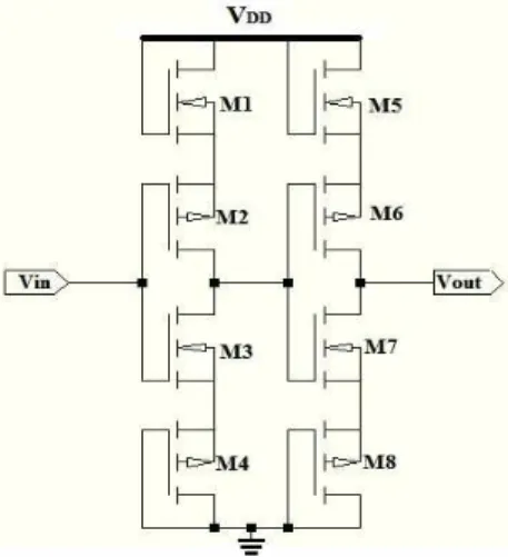
![Figure 1. TIQ Comparator [6]](https://thumb-eu.123doks.com/thumbv2/123dok_br/17166091.240991/2.918.318.583.749.992/figure-tiq-comparator.webp)

![Table 2. Comparison Summary of Simulation Results Parameter Proposed work Reported work [1] Reported work [2] Reported work [3] Reported work [10]](https://thumb-eu.123doks.com/thumbv2/123dok_br/17166091.240991/10.918.186.741.223.545/comparison-simulation-parameter-proposed-reported-reported-reported-reported.webp)
Documentos relacionados
“Analysis of a Zero Voltage Transition Boost Converter using a Soft Switching Auxiliary Circuit with Reduced Conduction Losses”, in IEEE Power Electronics Specialists Conference
The high frequency operation results in increased power loss in hard switching converters because switching losses are major contribution in the total converter
At first the converter have hard switching in main switch and completely analysis then added auxiliary circuit for soft switching Auxiliary circuit in the converter is not only
In order to increase the voltage gain in this topology, a boost converter used in series with the output stage of sepic converter, therefore the output voltage of
This implies that the obtainable maximum open circuit voltage (VOC) of solar cells using ( 1 ) as acceptor should be equal to the maximum open circuit voltage reachable with similar
The fuse network circuit can be mapped onto a directed graph, where each link corresponds to a circuit element 共 a resistor or a voltage source 兲 and the nodes simply correspond
Simulation circuit of WECS with PMSG using Fuzzy Logic controller is shown in the Figure 12 .The output voltage for Buck Boost Converter and SPWM based inverter is
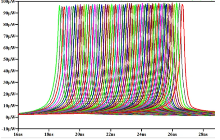
The measurement results show that the Buck converter is supplied with an input voltage of 1V and switching frequency of 155 kHz, an low power consumption (14uW), an output
