Telfor Journal, Vol. 1, No. 2, 2009. 49
Abstract — In the article, the Generalized Current Follower Transconductance Amplifier (GCFTA) element for generalized frequency filter design and a novel active element, the Programmable Current Amplifier (PCA) for the realization of the current-mode analog blocks, are presented. The paper also presents a method of general frequency filter design, whereas the basic circuit is a general autonomous circuit using GCFTA, PCA elements and general admittances. The properties of the proposed filter have been verified using PSPICE simulations.
Keywords — Active Filter, CCII+/–, Current-Mode Circuit, Generalized Current Follower Transconductance Amplifier (GCFTA), Multifunctional Filter, Programmable Current Amplifier (PCA).
I. INTRODUCTION
OR design of frequency filters a number of methods can be used. The adjoint transformation [1], method of higher-order synthetic elements [2], transformation using a passive prototype [3] or design using the M-C (Mason-Coates) signal-flow graph method [4] can be mentioned as examples. In our workplace, the method of generalized frequency filter design, when the initial circuit is a general autonomous circuit, has been developed [5], [6]. The same procedure has been used in the presented case of GCFTA and PCA elements.
The goal of this work is:
x definition of the Generalized Current Follower Transconductance Amplifier (GCFTA) element for general frequency filter design working in a current mode,
x presentation of a novel second-order multifunction frequency filter structure using active elements CFTA+/–, PCA and passive elements, whereas independent control of characteristic or cut-off frequency Ȧ0 and the quality factor Q of other
parameters of the frequency filter is enabled,
x presentation of proposed internal bipolar structure of the CFTA+/–,
The paper has been supported by the Czech Science Foundation project GACR 102/09/1681 and Ministry of Education of the Czech Republic project No. MSM0021630513.
Authors are with the Department of Telecommunications, Faculty of Electrical Engineering and Communication, Brno University of Technology, Purkynova 118, 612 00 Brno, Czech Republic (phone: +420-541-149-190; fax: +420-541-149-192; e-mails: {herencsn; koton; vrbak; latt; misurec}@feec.vutbr.cz).
x presentation of the realization possibility of the PCA using a current multiplier EL2082 and a second-generation current conveyor CCII+/–.
The designed multifunction filter enables realizing the low- (LP), band- (BP), high-pass (HP) and band-stop (BS) responses.
II. GCFTA AND PCA ELEMENTS
The Current Follower Transconductance Amplifier (CFTA) is a novel active element, which is suitable for the realization of current-mode analog blocks. For general frequency filter design it is more suitable to use the generalized GCFTA element. The schematic symbol of this element is shown in Fig. 1. The element is a combination of the Current Follower (CF) [7], [8] with the current transfer D, which is the input part of the GCFTA, and the Dual-Output Operational Transconductance Amplifier (DO-OTA) [9]-[11], which forms the output part of the element. The relation between the individual terminals of the GCFTA element can be described by the following hybrid matrix:
z z
x1,2 m x1,2
f f
0 0
0 0
0 0 0
i v
i g v
v i
D
ª º ª º ª º
« » « r » « »
« » « » « »
« » « » « »
¬ ¼ ¬ ¼ ¬ ¼
, (1) where parameter D of the Current Follower (CF) can have
the value of 1 or –1 and it denotes the current transfer from the terminal f to the auxiliary terminal z and the gm
denotes the transconductance of the output part of the GCFTA. Hence, six types of CFTA amplifiers can be defined, which are described in Table 1.
Fig. 1. Schematic symbol of GCFTA.
TABLE1: DEFINITION OF BASIC TYPES OF CFTA AMPLIFIERS.
D gm Type
1 1 1 CFTA+/+ 1 1 –1 CFTA+/– 1 –1 –1 CFTA–/– –1 1 1 ICFTA+/+ –1 1 –1 ICFTA+/– –1 –1 –1 ICFTA–/–
Generalized Design Method for
Voltage-Controlled Current-Mode Multifunction Filters
Norbert Herencsár, Student Member, IEEE, Jaroslav Koton, Kamil Vrba, Members, IEEE, Ivo Lattenberg, and JiĜí Mišurec
Telfor Journal, Vol. 1, No. 2, 2009. 50
Fig. 2. Schematic symbol of PCA.
On the basis of research results in pure current-mode circuits at the Brno University of Technology the new active element PCA (Programmable Current Amplifier) [12] has been defined. Currently, in cooperation with ON Semiconductor we work on the microelectronic structure realization of this element. The schematic symbol of the PCA element is shown in Fig. 2.
Relations between the individual terminals of the PCA element can be described by a hybrid matrix as follows:
1 1
2 2
3 3
0 0 0
0 0 0 0
v i
i n v
i n v
ª º ª ºª º
« » « »« »
« » « »« »
« » «¬ »¼« »
¬ ¼ ¬ ¼
, (2)
wherei1 is the input current, i2 and i3 are output currents of
the element and parameter n is the current mu-factor, whose value could be from +/–1 to cca +/–50 (limited by reason of realization in an integrated form).
III. INTRODUCTION
An autonomous circuit is a circuit that does not have excitation sources and it does not have a defined input terminal either. Such a circuit has the so-called characteristic equation in the form of a sum of the products of admittances Yx, from which we can already
read a possible application of this circuit, namely either as an oscillator or as various types of frequency filter.
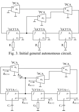
Fig. 3. Initial general autonomous circuit.
Fig. 4. Designed current-mode frequency filter.
In the implementation of filters, emphasis is placed on their maximum simplicity. Advantageous filters are those which have a maximum of grounded passive elements with a view to easy integration of circuits or easy electrical tunability. In this case for tunability we have used the properties of the PCA active elements. The designed autonomous circuit shown in Fig. 3 corresponds to these requirements. On the presented autonomous circuit the whole design procedure of frequency filter design is shown. The characteristic equation of this circuit obtained using the SNAP software [13] is:
1 2 3 2 3 2 3 1 m2 m3 1 3 1 2 3 m1 m2 m3
= +n nD D g g +n nD D D g g g =
D Y Y Y Y .
(3)
In the filter design we have restricted only to CFTA+/– [14] element. Due to choosing the passive elements
Y1 = sC1,Y2 = G2, and Y3 = sC3 equation (3) changes to a
form which satisfies the feasibility conditions of the frequency filter:
2
1 3 2 2 3 1 m2 m3 1 3 m1 m2 m3
= +C C G n n C g g +n n g g g 0
D s s , (4)
where s = jȦ is a complex variable. The designed frequency filter of the type SIMO (single-input-multi-output) working in a current mode is shown in Fig. 4. The complex current transfer functions of the designed filter with driving current IIN have the form:
OUT1 1 3 m1 m2 m3 IN
LP :I n n g g g
I D , (5)
2 OUT2 1 3 m2
IN
HP :I s C C g
I D , (6)
OUT3 1 2 m2 IN
BP1:I sC G g
I D , (7)
OUT4 1 3 1 m2 m3 IN
BP2 :I n n C gs g
I D , (8)
OUT5 2 3 1 m2 m3 IN
BP3 :I n n C gs g
I D , (9)
2
OUT1 OUT2 1 3 m2 1 3 m1 m2 m3
IN
BS :I I sC C g n n g g g
I D . (10)
The circuit designed according to Fig. 4 is multifunction, i.e. it allows a second-order low-pass filter (LP), band-pass filter (BP1, BP2, and BP3), and high-pass filter (HP) and band-stop filter (BS) to be implemented.
According to (4), the characteristic frequency Ȧ0, the
quality factor Q and the bandwidth BW of these filters are:
m1 m2 m3 0 1 3
1 3 2
g g g n n
C C G
Z , (11)
1 3 2 m1 2 3 1 m2 m3
1 n C G g Q
n n C g g , (12)
0 2 3 m2 m3 3 2
BW n n g g
Q C G
Z
. (13) From equations (11) and (12) it is evident that the
characteristic frequency Ȧ0 can be tuned using current
mu-factorsn1 = n3 = n independently and the quality factor Q
can be controlled using current mu-factor n2 independently
Herencsár et al.: Generalized Design Method for Voltage-Controlled Current-Mode Multifunction Filters 51 IV. SENSITIVITYANALYSIS
The relative sensitivities [4] of the characteristic frequency Ȧ0 (11), the quality factor Q (12) and the BW
(13) for the constituent active and passive elements are:
0 0 0
1,3, m1, m2, m3 1, 3, 2 1 2 , 2 0
n n g g g C C G n
SZ SZ SZ , (14)
1, 3, 2, m1 3, 1, m2, m3 1 2, 2 1
Q Q Q
n C G g n C g g n
S S S , (15)
2 3 m2 m3 3 2 1 1 m1
BW BW BW
, , , 1, , , 0
n n g g C ,G n C g
S S S . (16)
From these results it is evident that the sensitivities are low, which is an advantage of this structure.
V. SIMULATIONRESULTS
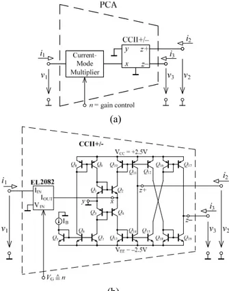
The characteristics of the designed multifunction filter structure have been verified using PSPICE simulations. The schematic symbol, block diagram and the used internal structure of the CFTA+/– element are shown in Fig. 5. The block diagram of the PCA element is shown in Fig. 6 (a). Current multiplier EL2082 [15] and the second-generation current conveyor CCII+/– bipolar structure [16] have been used for the simulation of PCA element, which is shown in Fig. 6 (b). In the design the transistor model parameters NR100N (NPN) and PR100N (PNP) of bipolar arrays ALA400 from AT&T [17] have been used. Bias currents IB = IB1 = 400 ȝA have been chosen. The
transconductance gm of CFTA+/– elements can be set by
current IB2 = gm/20. The simulated frequency
characteristics of the circuit in Fig. 4 are shown in Fig. 7. For the current mu-factors n1 = n2 = n3 = 1.012, for the
characteristic frequency f0§ 300 kHz and for the quality
factor of filters Q = 1 the following values have been chosen: C1 = C3 = 450 pF, G2 = 1 mS (R2 = 1 k:) and
gm1 = gm2 = gm3 = 1 mS (IB21 = IB22 = IB23 = 50 PA). The
possibility of tuning the characteristic frequency of band-pass filter (9) is shown in Fig. 8. For the current mu-factor n = {0.126; 0.331; 1.012; 3.598} according to (11) the characteristic frequency has the values as follows: f0 = {30; 100; 300; 1 000} kHz, where (Ȧ0 = 2Sf0). It is
evident from simulation results that the final solution corresponds to theory.
(a) (b)
(c) Fig. 5. (a) Schematic symbol, (b) block diagram, and (c) used bipolar implementation of CFTA+/– element.
(a)
(b) Fig. 6. (a) Block diagram of PCA element, (b) realization
of the PCA using current multiplier EL2082 and second-generation current conveyor CCII+/–.
-60 -40 -20 0
10k 100k 1M 10M
Frequency (Hz)
Gai
n
(d
B
)
HP
BS LP
BP3
Fig. 7. Simulation results of current-mode multifunction filter in Fig. 4.
-60 -40 -20 0
10k 100k 1M 10M
Frequency (Hz)
Gai
n
(d
B
)
n = 0.126
n = 1.012 n = 0.331
n = 3.598
Telfor Journal, Vol. 1, No. 2, 2009. 52
-60 -40 -20 0
10k 100k 1M 10M
Frequency (Hz)
Gai
n
(d
B
)
n2 = 0.102
n2 = 1.415
n2= 0.025
n2 = 0.334
n2 = 6.667
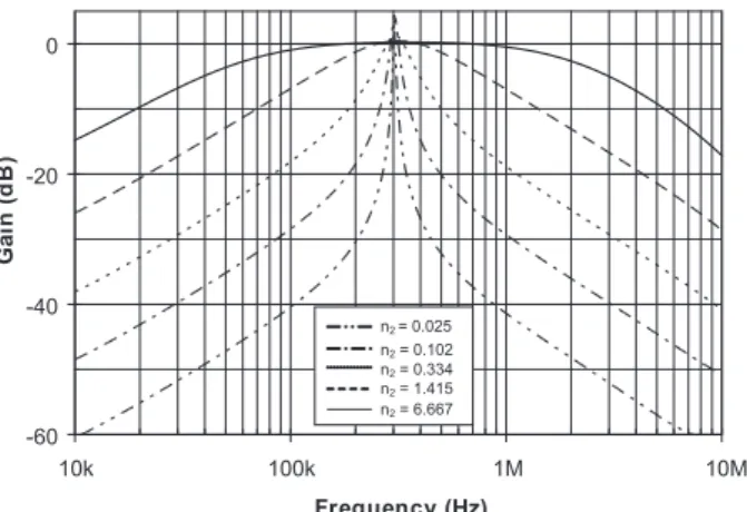
Fig. 9. Simulation results of controlling the quality factor Q for current-mode band-pass filter BP3 shown in Fig. 4.
0.01 0.1 1 10
0.01 0.1 1 10
n, n2 (-)
F
re
q
ue
ncy
(MHz)
0.1 1 10 100
Q (-)
Q = f (n2)
Frequency = f (n)
ideal simulation
Fig. 10. Simulation results evaluation according to Fig. 8 and Fig. 9.
The possibility of controlling the quality factor Q of the current-mode band-pass filter BP3 for the characteristic frequency f0§ 300 kHz using current mu-factor n2 is
shown in Fig. 9. For n2 = {0.025; 0.102; 0.334; 1.415;
6.667} according to (12) the quality factor has the values as follows: Q = {0.15; 0.707; 3; 10; 40}. These simulations show that the designed multifunction filter with a low value of current mu-factor n the characteristic frequency can be tuned over two decades with a high quality factor Q.
The simulation results according to Fig. 8 and Fig. 9 are shown in Fig. 10. The possibility of tuning the characteristic frequency by current mu-factor n and controlling the quality factor by current mu-factor n2 of
the proposed filter is shown in Fig. 10. The gain error of the current mu-factor of the current multiplier EL2082 element is for VG = 2 V about –3.8 % [15], which is also
evident from these simulations. From these simulations it is also evident that the most exact results are for current mu-factors n|n2| 1.
VI. CONCLUSION
The paper presents a generalized element GCFTA and a novel active element PCA. These active elements can be used for generalized design of tunable current-mode analogue filters. The possible internal bipolar structure of CFTA+/– element and the realization of the PCA using current multiplier EL2082 and the second-generation current conveyor CCII+/– are given. The presented
current-mode frequency filter has been designed using a generalized frequency filter design method and it allows a mutually independent change of characteristic frequency
Ȧ0 and quality factor Q. The tuning of characteristic
frequency Ȧ0 can easily be enabled using current
mu-factors of the 1PCA and 3PCA elements (by parameter n) and the control of the quality factor Q for a current-mode band-pass can be provided using current mu-factor of the
2
PCA element (by parameter n2). In the structure, all
passive elements are grounded which is advantageous because of the easy realization of grounded passive elements in integration. All current responses are taken directly from the high-impedance outputs of active elements. The filter enables realizing simultaneously LP, BP and HP filter responses. The band-stop filter can be realized by a suitable connection of current outputs. The sensitivities of the filter to the active and passive elements are low.
REFERENCES
[1] G. W. Robetrs and A. S. Sedra, “All Current-mode Frequency Selective Filters,” Electronics Lettres, vol. 25, no. 12, pp. 759–760, 1989.
[2] O. Cicekoglu, A. Toker, and H. Kuntman, “Universal immittance function simulators using current conveyors,” Computers and Electrical Engineering, vol. 27, no. 3, pp. 227–238, 2001.
[3] Y. S. Hwang, S. I. Liu, D. S. Wu, and Y. P. Wu, “Table-based linear transformation filters using OTA-C techniques,” Electronics Letters, vol. 30, no. 24, 1994.
[4] W. K. Chen, The Circuits and Filters Handbook. New York, CRC Press, 2003.
[5] J. Koton and K. Vrba, “Method for designing frequency filters using Universal Current Conveyors,” Int. Trans. on Computer Science and Engineering, vol. 13, no. 1, pp. 144–154, 2005. [6] N. Herencsár and K. Vrba, “Generalized Design of Current-Mode
Filters using BOTAs,” J. of Active and Passive Electronic Devices, to be published.
[7] J. J. Chen, C. C. Chen, H. W. Tsao, and S. I. Liu, “Current-mode oscillators using single current follower,” Electronics Letters, vol. 27, no. 22, pp. 2056–2059, 1991.
[8] S. I. Liu, J. J. Chen, H. W. Tsao, and J. H. Tsay, “Design of biquad filters with a single current follower,” IEE Proceedings—G, vol. 140, no. 3, pp. 165–170, 1993.
[9] Y. Sun and J. K. Fidler, “Structure generation of current-mode two-integrator loop dual output-OTA grounded capacitor filters,” IEEE Trans. Circuits and Systems—II, vol. 43, no. 9, pp. 659–663, 1996. [10] S. A. Mahmoud and A. M. Soliman, “A CMOS programmable
balanced output transconductor for analogue signal processing,” Int. J. of Electronics, vol. 82, no. 6, pp. 605–620, 1997.
[11] N. Herencsar and K. Vrba, “Current conveyors-based circuits using novel transformation method,” IEICE Electronics Express, vol. 4, no. 21, pp. 650–656, 2007.
[12] J. Koton, K. Vrba, P. A. Ushakov, and J. Misurec, “Designing electronically tunable frequency filters using the signal flow graph theory,” in Proc. 31th International Conference on Telecommunications and Signal Processing – TSP 2008, Paradfurdo, Hungary, 2008, pp. 41–43.
[13] D. Biolek and Z. Kolka, SNAP – symbolic, semisymbolic, and numerical analysis of electronic circuits. User guide available: http://snap.webpark.cz/indexa.html.
[14] N. Herencsar, J. Koton, K. Vrba, and I. Lattenberg, “Novel SIMO type current-mode universal filter using CFTAs and CMIs,” in
Proc. 31th International Conference on Telecommunications and Signal Processing – TSP 2008, Paradfurdo, Hungary, 2008, pp. 107–110.
[15] Datasheet EL2082: http://www.intersil.com/data/fn/fn7152.pdf. [16] A. Fabre, O. Saaid, F. Wiest, and C. Boucheron, “Current controlled
bandpass filter based on translinear conveyors,” Electronics Letters, vol. 31, no. 20, pp. 1727–1728, 1995.