Resumo
Os sistemas de armazenagem industrial são, em geral, construídos em peris formados a frio, com seções especialmente desenvolvidas para facilitar sua montagem, as seções “rack”, que têm perfurações ao longo de sua altura para ixar as ligações. Essas particularidades induzem um comportamento diferenciado, em relação a outras seções. Devido à complexidade de sua análise, essas seções são, em geral, estudadas via métodos numéricos. O objetivo desse trabalho é o de desenvolver um modelo via elementos initos para determinar a carga de lambagem e o modo de colapso de colunas formadas a frio perfuradas. Essa análise é feita, utilizando-se o software ANSYS, e a escolha do elemento, do reinamento da malha e da deinição das condições de contorno é, cuidadosamente, determinada, a im de garantir precisão ao modelo. A calibração do modelo é feita a partir da comparação com resultados da Teoria Generalizada de Vigas (GBT). Finalmente, os resultados numéricos são comparados com resultados experimentais. Essa comparação mostrou boa correlação, indicando que o modelo é adequado para a análise proposta.
Palavras-chave: Sistemas de armazenagem industrial, elementos formados a frio
perfurados, elementos initos, colunas.
Abstract
Industrial Storage Systems are usually built with cold-formed proiles, and their sections, called “rack section”, are specially designed to make its assemblage easier, having perforations throughout their elements to it connections. This section geometry with holes induces unexpected behavior in other sections. The analysis of these columns is quite complex, and is usually done by computational methods. The main objective is to develop a inite element model to determine the buckling load and mode failure in cold-formed perforated columns. This analysis is carried out using commercial ANSYS software. The choice of element type, mesh reinement and boundary condition settings is carefully done, to ensure that the inite element model reproduces actual column behavior. The model is irst calibrated with results from the Generalized Beam Theory (GBT). Finally, inite element results are compared to experimental data. This comparison presented a good agreement, indicating that the model is suitable for the proposed analysis.
Keywords: Industrial storage systems, thin walled perforated members, inite element analysis, columns.
Theoretical and experimental
analysis of perforated rack
columns
Análise teórico-experimental de colunas
perfuradas do tipo rack
Arlene M. S. Freitas
Departamento de Engenharia Civil, Escola de Minas,
Universidade Federal de Ouro Preto. arlene@em.ufop.br
Marcílio S. R. Freitas
Departamento de Engenharia Civil, Escola de Minas,
Universidade Federal de Ouro Preto. marcilio@em.ufop.br
Flávio T. Souza
Instituto Federal de Minas Gerais, Campus Ouro Preto.
lavio.souza@ifmg.edu.br
Guilherme G. Silva
Departamento de Engenharia Civil, Escola de Minas,
Universidade Federal de Ouro Preto guigabriel.silva@gmail.com
Vinícius O. Faria
Departamento de Engenharia Civil, Escola de Minas,
Universidade Federal de Ouro Preto viniciusjacks@yahoo.com.br
1. Introduction
Industrial Storage Systems are wide-ly used in factories, warehouses and other places where high storage density is needed. They are usually built by cold-formed proiles, and their sections, called “rack section”, are specially designed to make assemblage easier,. In addition, columns have perforation arrangements throughout their elements to it connec-tions and bolts. The special rack sec-tion and its perforasec-tion sets modify the column behavior and resistance because these holes induce unexpected failure modes in other sections, i.e., channel. So, in this case, local plate buckling and/ or distortional or global buckling occur. There are several works that analyze rack systems. They are focused on global sys-tem stability and in the behavior of their components (Freitas (2005, 2010), Godley (2000, 2002)). There are also recent works that consider perforation sets (Moen and
Schaffer (2008), Eccher, Rasmussen and Zandonini, 2008).
The existence of perforations modi-ies the columns behavior. This analysis is especially dificult because available nu-merical tools, such as inite strip analysis (CUFSM (Schaffer and Àdáni (2006))) and generalized beam theory (GBTul-Bebiano et al (2008)) are used only to evaluate full sections, i.e. without holes. Thus, the analysis of a perforated rack column must be carried out using inite element analysis.
This paper shows a inite element analysis of rack sections with perforations. The purpose of this analysis is to develop a inite element model, in ANSYS (2007) software, which predicts the buckling load of the cold-formed perforated columns. This elastic buckling load is important for design methods, like the Direct Strength Method.
The development of a inite element model should consider many important aspects, such as inite element type, mesh reinement, and the loading and bound-ary conditions. The model is often very sensitive to these parameters, and these can lead to an inaccurate inite element model. The model consists of a stub col-umn with ixed ends, under pure compres-sion. In the irst step, the results of column without perforations, analyzed by FEM Generalized Beam Theory (GBT), were compared in order to evaluate the inite element model suitability for buckling load prediction. So, the inite element parameters were adjusted to obtain good precision. Perforations were introduced into the inite element models, using the parameters previously adjusted in the irst step. The results were compared to experimental ones.
2. Finite element model development
A finite element model for cold-formed compressed members was devel-oped. Analyses were carried out in order to develop and validate the inite element
procedure to evaluate the without-hole col-umn behavior by comparison with other numerical technique results. A commercial rack section was chosen from a Brazilian
rack industry (Águia (2011)). The section components and dimensions are shown in Figure 1. At this stage, only columns without perforations were considered.
Figure 1
Column elements and dimension (in mm).
Columns with pinned ends (Free warping)
Now, analysis of rack sections without holes is carried out in the inite strip method (CUFSM), generalized beam theory (GBTul) and inite element method (ANSYS).
First of all, the generalized beam theory analysis was carried out in GBTul and the results were compared with the ones from the inite strip method. In a second stage, the data obtained from these analyses was compared to the inite element results for columns with pinned
ends, carried out for a few column lengths. Pinned conditions were chosen due to sim-plicity in inite element modeling and to permit comparison with the results from other numerical tools. In this stage, the inite element type and mesh reinement were deined.
The support conditions for the ends chosen to simulate pinned columns were the restrictions at translational degrees of freedom at end nodes in perpendicular directions to the column axis. In order to
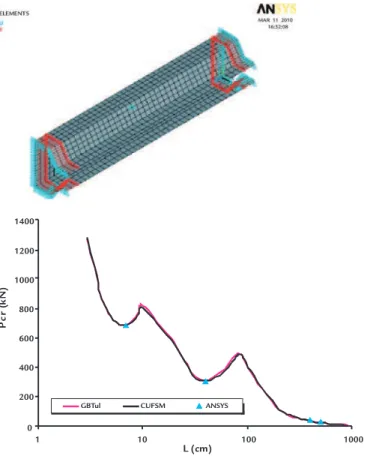
avoid rigid body displacement, the degree of freedom in axial direction of the middle height node was also constrained. Loading was applied by compressive forces to all end nodes at both extremities. An Eigen buckling analyses was carried out in order to evaluate buckling load and column failure mode. Figure 2 shows the inite element model.
There are simulated column lengths in that the irst buckling mode was a local mode (70 mm), distortional mode (400
mm), torsional lexural mode (4000 mm) and lexural mode (5000 mm). Results
obtained from these analyses are shown in Figure 3. It can be seen that the inite
ele-ment model, in general, is suitable to capture the failure mode and the buckling load.
Deinition of the inite element type and mesh reinement.
Three shell element types were tested to simulate the column: SHELL63, SHELL181 and SHELL281. They are similar and have the same input data. The ANSYS manual indicated that SHELL63 is suitable for elastic analysis, SHELL181 is strongly indicated for plastic analysis and SHELL281 has a midside node, i.e., this element has eight nodes, while SHELL63 and SHELL181 have four nodes.
Element SHELL281, due to the fact that it has quadratic approximation, usu-ally leads to better results, but increases
processing time. Element SHELL181 has two options. The default option uses reduced integration, but in this work, full integration was used, due to the improve-ment in the results provided by this option. Finite element type deinition was based on accuracy and processing time. Results from the inite element method (ANSYS) were compared to GBTul and CUFSM results. From these analyses, it was observed that the best element, considering the basic assumptions, was SHELL181 with full integration. This element was, then, adopted. Once again
the inite element type was chosen, the mesh refinement suitable for columns was analyzed. This was provided by com-parison with inite strip and generalized beam theory results. For these analyses, the manual element size set-up available in ANSYS was used. A range of element side sizes were tested, and the best result agreement was observed with element size equal to 10% web width (8,4 mm). Column lengths were chosen in order to induce local (70 mm) and distortional (400 mm) buckling modes.
Figure 2 Finite element model with pinned ends.
Figure 3 Comparison ofGBTul, CUFSM and ANSYS results.
Columns with ixed ends
After choosing the element type and mesh reinement, the column with ixed ends was analyzed. Consideration of this support condition is very impor-tant because this situation was observed in experimental tests, where load plates restrict warping effects. For this analysis, a generalized beam theory simulation carried out in GBTul is used as reference.
The inite element model developed to carry out this analysis is similar to the model presented in Figure 2. Element SHELL181 and the refinement level
presented in section 2.1 were used in this model. The main difference between models with pinned and ixed ends is that in the latter, end nodes have all degrees of freedom (translational and rotational) coupled, which assures that all of them will move on the same way, and the warp-ing effects are completely restricted. Two nodes in each column extremity have translational degrees of freedom restricted in perpendicular directions to the column axis, and the axial degree of freedom the node at mid height of the column was
constrained. Loading was applied at all end nodes.
Various column lengths were simu-lated in ANSYS by Eigen buckling analysis, in order to obtain a buckling curve. Comparison between inite ele-ment (ANSYS) and GBT (GBTul) results is shown in Figure 4. An excellent fit between results can be observed, which indicates that the inite element protocol developed is suitable to evaluate columns with perforations.
0 200 400 600 800 1000 1200 1400
1 10 100 1000
L (cm)
P
c
r
(k
N
)
Figure 4
Comparison between GBtul and ANSYS with ixed ends.
3. Experimental analysis
In order to evaluate the inite element eficiency in predicting buckling loads in cold-formed perforated columns, a series of specimens were tested in the Laboratory of Structures “Prof. Altamiro Tibiriçá Dias” at the Federal University of Ouro Preto, Brazil. Columns, with and without holes, were tested and the results were compared to those of the inite element analysis.
The specimens tested were stub col-umns with ixed ends under compression. In order to assure warping restriction and the ixed conditions, plates were welded at both extremities. Figure 5 shows the specimen section. The specimens were 412 mm high. Dimensions were chosen in order to avoid material yielding failure and to induce the occurrence of web local buckling. Linear inite element analysis was carried out previously to verify the specimen behavior and verify their suit-ability for this study.
Two column types were tested: without holes and with two square holes in the web, at mid height in the specimen. The experimental tests were carried out in a Universal Testing Machine InstronSatec Series 5569. This machine permits load application velocity control and complete testing settings from speciic software “Partner”. Parallel data acquisition from HBM Spider8 was used in order to get all data needed in this analysis. Figure 5 shows the specimen positioned in the uni-versal testing machine, and the specimens without and with holes.
There were specimens with two thicknesses: 1.5 mm and 1.8 mm, respec-tively. Three specimens of each thickness, with and without holes, were tested and then, the buckling load for each one was determined. The test set-up was deined in order to assure that specimens were under pure compression. Loading was applied with displacement control, and the
loading rate was limited to avoid abrupt collapse, permitting complete phenomena observation.
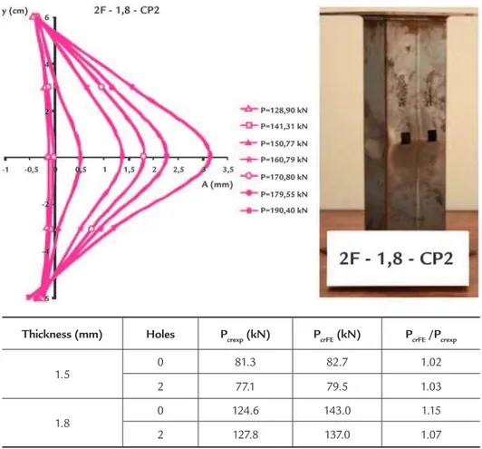
Linear displacement transducers were positioned in the specimen web to observe its behavior. A set of ive transduc-ers were used (Figure 6), and their data were registred by Instron Software Partner (Instron (2008)) and HBM Software Cat-Man (HBM (2003)). Twelve specimens were tested, and all of them showed local buckling in the web. Figure 6 shows a tested specimen and displacement in its web. In these graphs, the vertical axis shows displacement transducer position and the horizontal axis shows horizontal displacement amplitude. It can be seen that after the load of 141.31 kN, there is an increase in horizontal displacement, what indicates the local buckling. It can also be observed in the specimen photograph, the displacements indicated in the graph.
Figure 5
(A) Specimen positioned in testing machine.
(B) Specimen without holes. (C) Specimen with holes.
4. Finite element analysis
The inite element model developed previously was used to analyze the speci-mens tested, as shown above. The purpose
of this analysis is to determine the buck-ling loads in order to compare them to the experimental results. The model has ixed
end conditions, and uses the element type and mesh reinement deined in item 2.
The model was used in linear
buck-L (cm)
P
c
r
(k
N
)
0 200 400 600 800 1000 1200
1 10 100 1000
GBTul ANSYS
ling analysis in ANSYS. In this analysis, the buckling loads (Eigenvalues) and the buckling modes were determined, and the results were compared to experimen-tal ones. Table 4 presents results from numerical and experimental analysis. The experimental results showed a mean
value for each type of specimen, and in all situations the inite element model has shown the buckling mode observed in actual specimens.
From results in Table 4, it can be observed that there is a good precision in buckling load prediction, with deviation
being between 2% and 15%. It can also be observed that the existence of the square holes in specimen at mid-height produced an insigniicant impact on the buckling load and stub column behavior.
Figure 6 Test results for specimen with holes.
Table 4 Comparison between numerical
and experimental results
Thickness (mm) Holes Pcrexp (kN) PcrFE (kN) PcrFE /Pcrexp
1.5 0 81.3 82.7 1.02
2 77.1 79.5 1.03
1.8
0 124.6 143.0 1.15
2 127.8 137.0 1.07
5. Conclusions
The inite element method can be applied to many physical problems, includ-ing a large variety of structural problems. This method, however, is very sensitive to parameters such as mesh reinement and boundary condition settings. This work presents a inite element method procedure
to evaluate the linear buckling of cold-formed perforated columns. The inite element results were irstly compared to results from Generalized Beam Theory for columns without holes in order to validate the model. So, these results are compared to experimental results for columns with
and without holes. From this comparison, a good agreement between experimental and numerical results was shown, demon-strating the model eficiency and indicates the possibility of its use in other analyses, including material non linearity and sec-ond order effects.
6. Acknowledgments
Authors would like to thanks the company Águia Sistemas de
Armazena-gem and CAPES, CNPq and FAPEMIG agencies for supporting this research.
7. References
Águia Industrial Storage Systems. Design of a drive-in storage system. 2011.
ANSYS. User´s manual for revision 11.Swanson Analysis Systems Inc.; Houston, PA; 2007. BEBIANO, R., PINA, P., SILVESTRE, N., CAMOTIM, D. GBTUL – Buckling and
vibration analysis of thin-walled members, DECivil/IST, Technical University of Lisbon ( http://www.civil.ist.utl.pt/gbt), 2008.
FREITAS, A.M.S., FREITAS, M.S.R., SOUZA, F.T. Analysis of steel storage rack columns. Journal of Constructional Steel Research, v. 61, n. 8, p. 1135-1146, 2005. FREITAS, A.M.S., SOUZA, F.T., FREITAS, M.S.R. Analysis and behavior of steel
storage drive-in racks. Thin Walled Structures, v. 61, n. 8, p. 1135-1146, 2010. GODLEY, M.H.R. The bahavior of drive-in storage structures. In: INTERNATIONAL
SPECIALTY CONFERENCE ON COLD-FORMED STEEL STRUCTURES, 16. Proc. Orlando, p. 340-352, 2002.
GODLEY, M.H.R., BEALE, R.G., FENG, X. Analysis and design of down-aisle pallet rack structures. Computers and Structures, v. 77, n. 4, p. 391-401, 2000. MOEN, C.D., SCHAFFER, B. W. Experiments on cold-formed steel columns with
holes. Thin-Walled Structures, 46, p. 1164-1182, 2008.
SCHAFER, B.W., ÁDÁNY, S. Buckling analysis of cold-formed steel members using CUFSM: conventional and constrained inite strip methods. In: INTERNATIONAL SPECIALTY CONFERENCE ON COLD-FORMED STEEL STRUCTURES, 18. Proc. Orlando, FL. October 2006.