Abstract
In the present research, a unified semi-analytical solution that incorporates influence of the auxeticity (negative Poisson ratio) of the material into elastic responses of the variable thickness func-tionally graded conical and cylindrical shells and circular/annular plates is developed. The top or bottom layers of the shell/plate may be subjected to general non-uniform normal and shear trac-tions. The mentioned material and loading complexities have not been investigated before and consequently, the presented compre-hensive results are quite new. The proposed unified formulation is developed using the principle of minimum total potential energy and solved using Taylor’s transform, for some combinations of the simply supported, clamped and free edge conditions. Accuracy of results of the proposed unified solution is verified by results of the three-dimensional theory of elasticity extracted from the ABAQUS finite element analysis code. Finally, a comprehensive parametric study including evaluation of individual/simultaneous effects of the auxeticity, structure configuration, shear/normal traction, thickness variability, and boundary conditions on the resulting lateral deflec-tion and in-plane stress distribudeflec-tions of the considered shell and plate structures is accomplished.
Keywords
Taylor’s transform; Bending and stress analysis; Auxetic FGM conical and cylindrical shells; Non-uniform shear and normal trac-tions.
Analytical Bending and Stress Analysis of Variable Thickness FGM
Auxetic Conical/Cylindrical Shells with General Tractions
1 INTRODUCTION
Simpler manufacturing requirements and more geometrical consistency with the nature of the ap-plied loads have led to extensive use of the shells of revolution in many mechanical, civil, aerospace, vehicular, and other engineering structures; especially as rotating, pressure containing, or aerody-namic components. These structures may sometimes be fabricated from functionally graded
materi-M. Shariyat a,* M.M. Alipour b
a Professor, Faculty of Mechanical Engineering, K.N. Toosi University of Technology, Tehran, Iran.
E-mail: [email protected]. b Assistant Professor, Department of Mechanical Engineering, University of Mazandaran, Babolsar, Iran.
E-mail: [email protected].
* Corresponding author
http://dx.doi.org/10.1590/1679-78253413
the single construction instead of using the multilayered structures that exhibit jumps in the mate-rial properties at the interfaces between layers. Circular/annular plates and cylindrical/conical shells are among the most common axisymmetric structures. Comprehensive descriptions of the theories presented so far on isotropic, composite, and FGM plates and doubly-curved shells may be found in books published by Reddy (2003), Shen (2009), Carrera et al. (2011), and Tornabene and Fantuzzi (2014). The cylindrical or conical shells (e.g., CNG pressure vessels and conical caps) produced by deep drawing or spinning of the billets or designed to meet specified criteria, are generally variable-thickness. On the other hand, the conical caps or thin cylindrical components may experience nor-mal and shear tractions; e.g., when they are subjected to aerodynamic, hydrodynamic, or inter-nal/external fluid flow forces.
In contrast to the extensive researches accomplished on displacement analysis, vibration (Nie and Zhong, 2007; Tornabene, 2009; Setoodeh et al., 2011; Shariyat and Alipour, 2011; Shariyat, 2012; Tahani et al., 2013; Duc, 2013; Mercan et al., 2016) or buckling (Sofiyev, 2007; Shariyat, 2008; Alipour and Shariyat, 2011, 2013; Shariyat and Asgari, 2013; Sun et al., 2014) of the FGM circular/annular plates and cylindrical/conical shells, limited works have been published on the stress analysis of the mentioned structures. A semi-inverse series elasticity solution was presented by Pelletier and Vel (2006) for thermoelastic analysis of a transversely graded orthotropic cylindrical shell. An mth-order shear-deformation theory was presented by Matsunaga (2009) for vibration and buckling analyses of the transversely graded cylindrical shells. Viola et al. (2012) conducted a para-metric investigation coupled with a stress recovery procedure for the FG cylindrical shells. A high-order theory was presented by Zozulya and Zhang (2012) for the axisymmetric FGM cylindrical shells. Asymmetric bending of the FGM circular plates was investigated by Nosier and Fallah (2009), using the first-order shear-deformation theory (FSDT). Wang et al. (2010) presented a three-dimensional solution for axisymmetric bending of FGM circular plates. Sburlati and Bardella (2011) developed three-dimensional elastic solutions for the axisymmetric FGM circular plates. Behravan Rad and Shariyat (2013) presented a 3D elasticity analysis for bidirectional FGM annular plates subjected to normal and shear tractions, on elastic foundations. Golmakani and Kadkhoda-yan (2014) investigated axisymmetric bending and stretching of FGM circular/annular plates with variable thicknesses under thermomechanical loads, using the FSDT and the finite difference tech-nique. Shariyat and Mohammadjani (2013,2014) conducted 3D elasticity stress and displacement analyses of rotating bidirectional FGM annular plates subjected to uniform loads and non-uniform elastic foundations. Alipour and Shariyat (2012) and Shariyat Alipour (2014) incorporated 3D elasticity corrections into results of the single-layer/sandwich plate theories of circular/annular plates under non-uniform shear and normal tractions. Recently, Behravan Rad and Shariyat (2015) conducted a three-dimensional magneto-elastic analysis for asymmetric variable thickness porous FGM circular plates with non-uniform shear and normal tractions and elastic foundations.
to internal/external pressure shocks. Abediokhchi et al. (2013) presented a bending analysis for the FGM conical panels based on the FSDT and generalized differential quadrature (GDQ) solution method. The FSDT and the perturbation theory were employed by Ghannad et al. (2013) for de-formation and stress analysis of axisymmetric clamped variable thickness FGM cylindrical shells under internal pressures. Tornabene et al. (2013) applied the GDQ Method, FSDT, and stress re-covery approach for stress analysis of transversely graded and laminated composite shells of revolu-tion. Sofiyev (2014) investigated large deformation dynamic buckling of truncated conical shells with functionally graded coatings under axial loads. Static analysis of FGM truncated conical shells subjected to meridian, circumferential and normal uniform loadings was conducted by Viola et al. (2014), using a third-order shear-deformation theory, GDQ method, and the stress recovery ap-proach. A hybrid method composed of the layerwise theory, DQM, and Fourier series expansion was developed by Selahi et al. (2014) for transient analysis of FGM truncated conical shells with variable thickness, under asymmetric dynamic pressures. Tornabene et al. (2015) investigated re-covery of the static transverse normal and shear stresses in FGM doubly-curved sandwich shells of revolution using Carrera’s unified formulation and the DQM. Using the FSDT and dividing the FGM shell into homogeneous disks, and using the finite element method, Zamani Nejad (2015) per-formed elastic analysis of rotating axially graded truncated conical shells under non-uniform pres-sures.
Very rare articles may be found in literature on elastic analysis of the auxetic structures. Khan and Hilton (2009) demonstrated that for the non-homogeneous linear elastic materials, the Poisson's ratio becomes both space and time dependent under time dependent stresses. Hilton et al. (2009) presented the idea of optimum 3-D anisotropic designer materials, including auxetic viscoelastic functionally graded ones. Brighenti (2014) studied effects of the auxetic materials on lateral deflec-tions of isotropic and homogeneous layered circular plates under uniform transverse loads, using the classical bending plate theory. Performance of sandwich panels with auxetic lattice cores confined between metallic facets were studied by Imbalzano et al. (2015) under localised impacts at high strain rates and a remarkable reduction was observed in the maximum back facet displacements, due to the localised densification of the auxetic core. Based on Reddy’s first-order shear deformation plate theory, Duc and Cong (2016) analyzed nonlinear dynamic response and vibration of sandwich plates with auxetic honeycomb cores on elastic foundations subjected to blast and mechanical loads. The only published paper on stress analysis of the auxetic structures was due to Alipour to Shariyat (2015) who developed analytical zigzag solutions with 3D elasticity corrections for bending and stress analysis of circular/annular composite sandwich plates with auxetic cores.
of results of the proposed Taylor transform solution is verified by those of the three-dimensional theory of elasticity obtained from the ABAQUS finite element analysis code.
2 THE UNIFIED FORMULATION
2.1 Description of Variations of the Thickness, Material Properties, and Normal and Shear Tractions
Geometric and load parameters of the considered general shell are illustrated in Fig. 1. The two limit values of the semi vertex angle (
a
), i.e., a =0 and a =p/ 2 (which correspond respective-ly, to the j = p/ 2and j =0meridian angles) are associated respectively, with the cylindrical shell and annular plate configurations.Figure 1: Geometric parameters and coordinate system of the considered variable thickness functionally graded auxetic shell with arbitrary distributions of the normal and shear tractions.
As may be noted from Fig. 1, thickness of the shell may vary in a general manner; so that dis-tances of the top and bottom layers of thickness may vary arbitrary, e.g., as follows, with respect to the reference surface of the shell, in the meridian direction:
= + +
= + +
2 2 ( )
( )
t t t t
b b b b
h x a b x c x
h x a b x c x (1)
where the subscripts t and b denote the top and bottom surfaces of the shell, respectively, and the coordinate z is measured from the reference surface of the shell (Fig. 1):
< <
( ) ( ) ( )
b t
h x z x h x (2)
=
-( ) t( ) b( )
h x h x h x (3)
Moreover, the top and bottom layers of the thickness may be prone to normal and shear trac-tions whose intensity vary arbitrary along the meridian direction, e.g., according to the following parabolic forms (Fig. 1):
t a b g
t a b g
h l x
= + +
= + +
= + +
2
2
2
ˆ ( ) ˆ ( )
( )
t t t t t
b b b b b
t
T x x
T x x
q q x x
(4)
where the symbols q and
t
stand for the normal and shear tractions and. ˆ ˆ, ,t b
T T qare amplitudes of the shear and normal tractions, respectively, and ( , ,a b gt t t),( ,a b gb b, b),( , , )h l x are the relevant load-ing coefficients.
It is assumed that the conical shell (or equivalently, the cylindrical shell or annular/circular plate) are fabricated from a mixture of ceramic and metal constituent materials whose material compositions vary continuously in the thickness direction. Some researchers have shown that results of Voigt’s rule of mixtures and Mori-Tanaka micromechanical homogenization techniques are gener-ally close (Ferreira et al., 2005; Alipour and Shariyat, 2015), unless constituent materials with quite different Poisson ratios are employed (Shariyat and Asemi, 2014). On the other hand, one of moti-vations of the present research is investigation of effects of the auxicity nature of the material prop-erties through comparative analyses. Therefore, both models may be used in the mentioned com-parative analyses. According to the rule of mixture, transverse variations of the effective elastic moduli of the shell/plate may be expressed as follows:
( ) ( , ) ( ) ;
( )
g t
c m c m c
h x z
E x z E E V E V
h x é - ù
ê ú
= - + = ê ú
ë û (5)
where g is the positive definite volume fraction index and the subscripts c and m refer to the ceram-ic and metallceram-ic constituent materials, respectively. The ceramceram-ic volume fraction, Vc, is so defined that, the top layer (z =h xt( )) becomes a metal-rich (Vc =0) and the bottom layer (wherein,
( ) ( )
b t
z = -h x =h x -h) becomes a ceramic-rich (Vc =1) one.
2.2 The Governing Equations
According to the first-order shear-deformation theory, the displacement field of the axisymmetric shell may be described as follows:
y
= +
= 0
0 x
u u z
w w (6)
q
e y
j
j y j
e g y = + = + + = + 0, , 0
0 0 0
,
, sin
cos cos ,
x x x x
x
xz x x
u z
w u
z
R R R
w
(7)
where ex and eq are the normal strain components and gxz is the transverse shear strain. R0 is the radius of the cone at a plane perpendicular to cone axis:
j
= +
0 b cos
R R x (8)
where Rb corresponds to the starting edge of the truncated conical shell. The corresponding stresses may be obtained based on the generalized Hooke’s law as:
q
q q
s e e
s e ne
t g = + -= + -= + 2 2 ( ), 1 ( ), 1 2(1 ) x x x xz xz E v v E v E v (9)
The governing equations of the shell/plate may be derived by using the principle of minimum total potential energy:
dP =dU-dW = 0 (10)
where dP, dU, and dW are increments of the total potential energy, strain energy, and work of the externally applied loads, respectively:
ε σ
2 2 2
1 ( ) , 2 [( ) ] ˆ ˆ ( ) ( ) ( ) T
r r rz rz
V V
t b t t b b
A
t t t t t b b b b b
A
U dV dV
W q q w u u dA
q x x w T x x u T x x u dA
q q
d d s de s de kt dg
d d t d t d
h l x d a b g d a b g d
= = + +
= - + +
é ù
= êë + + + + + + + + úû
ò
ò
ò
ò
(11)
where A and V stand for the area and volume and
k
is the shear correction factor, e.g., k=5 / 6, and: y y = + = + 0 0t t x
b b x
u u h
u u h (12)
and t = tb at the top and bottom surfaces of the shell/plate. In contrast to the elasticity and equi-librium equations approaches, in the energy version of the three-dimensional theory of elasticity (that is the base of almost all the commercial finite element analysis codes), the traction or force boundary conditions may be imposed through including of the relevant works. Therefore, distribu-tions of the stresses and displacements so arranged that they finally become compatible with the mentioned traction conditions, through the principle of minimum potential energy. This fact is valid even for the stress fields formed around the concentrated loads of the structures.
Substituting Eq. (7) into Eq. (9) and substituting the resulting equations into Eq. (11) enables expressing of Eq. (10) in terms of the displacement parameters and their increments (du0,dy dx, w):
d + dy + d =
ò
( 0 x ) 0A
u w dA
(13)
where, e.g., º ( ,0 y , , , , , , , , ,j ˆ ˆ h l x a b g a b g, , , , , , , , , , , , , , , 0)
x t b t t t b b b c m t t t b b b
u w q T T g E E a b c a b c x
. Since
the displacement increments (du0,dy dx, w) are generally non-zero values for the interior points of the shell/plate, it may be deduced that their coefficients appeared in Eq. (13), i.e., , , and
are zero for those points. Therefore, the governing equations of the shell become:
q q
q
j a b g a b g
j a b g a b g
j j h l x
-= + = + + + + +
- é ù
= + - = êë + + - + + úû
= + - = + + 2 2 , 0 2 2 , 0 2 , 0 0 ˆ ˆ
0 : cos ( ) ( )
ˆ ˆ
0 : cos ( ) ( )
2
0 : cos sin ( )
x
x x t t t t b b b b
x
x x x t t t t b b b b
x x x
N N
N T x x T x x
R
M M h
M Q T x x T x x
R
Q N
Q q x x
R R
(14)
The stress resultants M, N, Q are:
q q
q q
j j j
s y y
j j j
s y y
j j j
s y y
j j s = = + + + + = = + + + + = = + + + + = = +
ò
ò
ò
ò
0, 0 ,
0 0 0
0 0, ,
0 0 0
0, 0 ,
0 0 0
0
0 0
cos sin cos cos sin cos
cos sin cos cos sin t b t b t b t b h
x h x x x x x
h
x x x x
h h
x h x x x x x
h h
N dz Au A u A w B B
R R R
N dz A u A w Au B B
R R R
M zdz Bu B u B w D D
R R R
M zdz B u B w
R R
jy y
k t k y
+ + +
=
ò
= + 0, , 0 , cos ( ) t b
x x x x
h
x xz x x
h
Bu D D
R
Q dz A w
(15)
where based on Eqs. (6), (7), and (9), one has:
ì ü ì ü ì ü
ì ü ï ï ì ü ï ï ì ü ï ï
ï ï ï ï ï ï ï ï ï ï ï
ï ï ï ï ï ï ï ï ï ï ï
ï ï ï ï ï ï ï ï ï ï ï
ï ï= ï ï ï ï= ï ï ï ï= ï
í ý í ý í ý í ý í ý í ý
ï ï - ï ï ï ï - ï ï ï ï + ï
ï ï ï ï ï ï ï ï ï ï ï
ï ï ï ï ï ï ï ï ï ï ï
ï ï ï ï ï ï ï ï ï ï ï
î þ î þ î þ
ò
ò
ò
2 2
2 2 2
1 1 1
, ,
2(1 )
1 1
t t t
b b b
h h h
h h h
A A A
E vE E
B z dz B z dz B z
v
v v
D z D z D z
ïï ïï ïï ïïïþ
or in expanded form:
ìï = + + ïï
ïï = + + íï
ïï = + + ïïî
ìï = + + + +
ïï
ïï = + + + +
íï
ïï = + + + +
ïïî = + + + + + + = + + + 2 0 1 2
2 0 1 2
2 0 1 2
2 3 4
0 1 2 3 4
2 3 4
0 1 2 3 4
2 3 4
0 1 2 3 4
2 3 4 5 6
0 1 2 2 2 5 6
2 3
0 1 2 2
A a a x a x
A a a x a x
A a a x a x
B b a x a x a x a x
B b b x b x b x b x
B b b x b x b x b x
D d d x a x a x a x a x a x
D d d x d x d x
ìïï
ïïï + + +
íï
ïï = + + + + + +
ïïî
4 5 6
2 5 6
2 3 4 5 6
0 1 2 2 2 5 6
d x d x d x
D d d x d x d x d x d x d x
(17)
Definition of the coefficients appeared in the right hand side of Eq. (17) is not included here, to save space. In this regard, Eq. (1) is employed as well.
The governing equations (14) may be rewritten based on Eqs. (15), as follows:
j j y jy jy j
j j j j y jy
h l m l g x
+ - + + - + - + + + + + = + + + + + 2 2
0, 0, 2 0 , , 2 ,
0 0 0 0 0
, 0, , 0 , , , ,
2
0 0 0
0
2 2
cos cos cos cos sin sin cos cos sin cos
( ) ( )
xx x x xx x x x x
x x x x x x x x x
t t t t b b b b
Au A u A u B B B A w
R R R R R
A w A u A u A w B B
R R R
R
T x x T x x
(18-a)
(
)
j j y y j jy j
j j k y j j y
jy h l m l g x
+ - + + - +
- - + + + + +
é ù
+ = êë + + - + + úû
2 2
0, 0, 2 0 , , 2 ,
0 0 0 0 0
, , 0, , 0 , , ,
2 0 0 0 2 2 , 0
cos cos cos cos sin sin cos cos sin
cos
( ) ( )
2
xx x x xx x x x x
x x x x x x x x x
x x t t t t b b b b
Bu B u B u D D D B w
R R R R R
B w A w B u B u B w D
R R
R
h
D T x x T x x
R
(18-b)
j j j j y j jy k y k jy
j j
k k k y
p j
a b g
- - - - + +
+ + - - + +
= + +
0, 0 , ,
2 2
0 0 0 0 0
2
, , 2 , , ,
0 0 0
2
sin cos sin sin cos sin cos cos sin
( ) 2 sin
( )
x x x x x x x
xx x xx x x x
A u A u B B A A
R R R R R
P
Aw A w A w w A w
R R R
q x x
(18-c)
2.3 Boundary Conditions
Some more common edge conditions are considered here to develop the semi-analytical solution: =
y = 0
Clamped edge: u , w, x 0, (19-b)
=
Free edge: N M Qx, x, x 0 (19-c)
3 THE UNIFIED TAYLOR TRANSFORM SOLUTION
According to the Taylor transform for the finite domains (Shariyat and Alipour, 2011; Alipour and Shariyat, 2011; Shariyat and Asemi, 2014), the displacement components may be expanded in series forms about the initial value of the meridian coordinate:
y ¥ = ¥ = ¥ = =
-= Y
-=
-å
å
å
0 0 0 0 0 0 0 ( ) ( ) ( ) ( ) ( ) ( ) i i i i x i i i i iu x U x x
x x x
w x W x x
(20)
Therefore, one may define the following expressions that have been appeared in Eq. (18):
(
)
j j
j
j j f
j f j j j j j ¥ = ¥ -= + ¥ = ¥ = ¶ = - = - = -+ ¶ = - + -æ ö÷ ç ÷ ç
= çç- ÷÷
-÷ + çè ø ¶ = = = -¶ + æç = + çç
-+ è
å
å
å
å
0 0 0 1 0 0 1 0 02 2 2
2 0 2 2 0 0 cos cos ( ) cos !
cos (cos ) ( cos ) ( ) cos ( ) cos( ) cos cos ( ) ! cos cos ( 1) cos j j j j b
j j j
b j j j j b j j j j b b Y
Y x x
R R x j x
R x x x
x x
R x
Y
Y x x
R R x j x
j R x + ¥ = ö÷÷ -÷÷ ç ø
å
2 00 ( ) j j j x x (21)
where x =x0is associated with a proper center of expansion. In the present research, x0 = 0 is
chosen. By substituting Eqs. (20) and (21) into the governing Eq. (14) and performing some ma-nipulations, the transformed form of Eq. (14) becomes:
+ + + - + - + - + = = = + - - -
-ìïïï- - + é + Y + ù- é
-í ë û êë
ïïïî
ù
+ Y + + + + Y + úû
å å
å
1
1 1
0 1 0 1 0 1
0 0 0
2
1 1 1 0 0 0
( 1) tan ( )
( tan ) ( 1) ( tan )
N i i
j j
i j i j i j
i j j
j
i j i j i j i j i j i j
i j Y a U b a W i j Y
a U b a W j Y a U b a W
j
j j
-+ + - - - -= -+ - - - - -= + - - - - -+ é
- êë - - + Y + + +
ù é ù
+ Y + úû- ë - - + û Y
+ + + Y +
- - - + Y
å
å
1 1 22 1 2 1 2 1 1 1
0
2
1
1 1 1 1 3 3 2
0 2
2 2 2 2 2 2
1 4 4
( 1)( tan ) ( 1) ( tan ) ( 2) 3
( 1) ( tan )
(( 3) 4 )
i
j j
i j i j i j i j
j
i
j
i j i j i j
j j
i j i j i j
j
Y i j a U b a W j Y a U
b a W i j b b Y
j Y a U b a W
i j b b Y
j j j - -+ + - - - - -= = -+ + - - - -= = - - + + + +
é + + Y ù- + Y
ê ú
ë û
- + Y + - + Y
+ + + + Y + + + + Y
å
å
å
å
3 4
2 2
3 3 3 4 4
0 0
1 ( )
1 1
1 1 1 2 1 2 1
0 0
2
2 1 1 1 1 1 0 2 0 2
( 1) ( 1) ( tan ) 2 [ (
tan )] ( 1) ( ) ( 2)( 1)(
i i
j j
i j i j i j
j j
i i
x
j j
i j i j i j i j i j
j j
i j i i i i
j Y b j Y b
Y a U b a W Y a U b
a W i a U b i i a U b
j
j
-
-+ + + Y + - + Y + + - Y
é ù
- êë + + + + - + - úû
- + + + + - + - =
2 2 3 1 4 2
2 2
) ( 1)( ) ( 1)( 1) ( 1)( 2)
( ) ( ) ( 2 ) ( 1) ( 2) ( ) ( ) ( 2 ) ( 1) ( 2)} 0
i i i i
t t t t t t t
i
b b b b b b b
i i a U b i i b b i i
T b b i b i i
T b b i b i i x
h l m d l m d m d
h l m d l m d m d
+ + - + - + - + = = + + + - - -= + - - -+
-ìïïï- é - + + Y + ù+ + +
í êë úû
ïïïî
é
+ Y - êë - + Y +
ù
+ + + Y + úû
-
-å -å
å
1 10 1 0 1 0 1
0 0
1
0 2 0 2 1 1 1
0 2
0 0 0
1
2
( 1)( tan ) ( 2)( 1)
( ) ( )( tan )
( 1) ( tan ) ( 1)(
N i
j
i j i j i j
i j
i j
i i i j i j i j
j j
i j i j i j
j
i
Y i j b U d b W i i
b U d Y i j b U d b W
j Y b U d b W
Y i j b U
j j j -+ - - - -= - - - - -+ + - - - - -= - - - - -+
é + Y + + +
êë
ù
+ Y + úû
é
- êë - - + Y + + +
ù
- + Y + úû
-
-å
å
1 21 2 1 2 1
0
1 1 1 1 1 1
2
1 2
3 2 3 2 3 2
0
2 2 2 2 2 2
1
4
tan ) ( 1)
( tan )
( 2)( tan ) ( 1)
( tan )
( 3)(
i
j
j i j i j
j
i j i j i j
i
j j
i j i j i j
j
i j i j i j
j
i
d b W j Y
b U d b W
Y i j b U d b W j Y
b U d b W
Y i j b U
j j j j -+ - - - - -= - - - - -+ + - - - -= + + - -
-é + Y + + +
êë
ù
+ Y + û
é ù
- êë - - Y + + + Y + úû
é ù
- êë - - Y + + Y û
å
å
3
2
3 4 3 4 3
0
3 3 3 3 3 3
4
1 2
5 4 4 4 4 4 4 4
0
1 2
6 5 5 5
tan ) ( 1)
( tan )
( 4) ( 1) ( tan )
( 5) ( 1)
i
j
j i j i j
j
i j i j i j
i
j j
i j i j i j i j
j
j j
i j i j
d b W j Y
b U d b W
Y i j d j Y b U d b W
Y i j d j Y d
j j j - -+ -= =
- + Y
ú
å
5å
6 26 6 0 0 ( 1) i i j i j j j
j Y d
-+ + - - - -= = -+ - - - -=
- + + Y - +
+ Y - + + Y
å
å
å
1 1 11 1 1 2 1 2 1
0 0
2 1
2 1 3 2 3 2 3 2
0
( tan ) 2 ( tan
) 3 ( tan )
i i
j j
i j i j i j i j i j
j j
i j
i j i j i j i j
j
Y b W b U d Y b W b U
d Y b W b U d
j j
j
- -+ + - - - -= = -+ - - + + = - - - -
-- + + Y - Y
- Y + + + Y + + + Y
+ - + + Y + - + + Y + - + Y
å
å
å
3 4 1 14 3 4 3 4 3 5 4
0 0
5
1 2
6 5 1 1 1 1 2 2
0
3 1 3 1 4 2 4 2 5
4 ( tan ) 5
6 ( 1) ( ) ( 1)( )
( 1)( 1)( ) ( 2)( 1)( ) ( 3)( 1)
i i
j j
i j i j i j i j
j j
i j
i j i i i i
j
i i i i i
Y b W b U d Y d
Y d i b U d i i b U d
i i b U d i i b U d i i d
j
- + - -
-+ - + Y - Y + + - Y + - Y +
-é ù
- êë + + + + - + - úû
üïï
é ù
+ êë + + + + - + - úý =
û ïïþ
3
6 4 0 1 1 1 2 2 1
2
2
( 4)( 1) ( ( 1) ) ( ) [ ( 1) ] ( ) ( ) ( 2 ) ( 1) ( 2)
2
( ) ( ) ( 2 ) ( 1) ( 2) 0 2
i i i i i i i
t t t t t t t
i
b b b b b b b
i i d a i W a iW a i W
h
T b b i b i i
h
T b b i b i i x
k k k
h l m d l m d m d
h l m d l m d m d
j j j + + - + - + = = + + - - - -= + + - - - -=
ìïïï - + + Y
íï ïïî
é ù
+ êë - + Y - + + Y úû
é ù
+ êë - - + Y - + + Y úû
å
å
å
1 10 1 0 1
0 0
1 2
1 1 0 0
0
1 2
2 1 2 1 1 1 1 1
0
tan ( 1)( )
tan ( )( ) ( 1) ( )
tan ( 1)( ) ( 1) ( )
N i
j
i j i j
i j
i
j j
i j i j i j i j
j i
j j
i j i j i j i j
j
Y i j a U b
Y i j a U b j Y a U b
Y i j a U b j Y a U b
j j j k k -+ + - - - - -= - -+ + + - - -= = + + + - - - + -= é ù
+ êë - - Y - + + Y úû
é ù
+ êë - - Y - + Y úû- +
Y - - + - Y +
å
å
å
å
å
1 2 1 23 2 2 2 2 2
0
3 4
1 2 2
4 3 3 3 4
0 0
1
1 1
4 0 1 0 1
0
tan ( 2) ( 1) ( ) tan ( 3) ( 1) tan ( 1)
( 1) (
i
j j
i j i j i j
j
i i
j j j
i j i j
j j
i
j j
i j i j i j
j
Y i j b j Y a U b
Y i j b j Y b j Y b
a Y i j W Y a a i
k k k
k k k k k
j j -= - -+ + - - - + = = - + + + + -= =
é - ù
ë û
é ù
- ë Y + - - û- Y + + Y
+ Y + - Y + + + + + +
-- + - +
å
å
å
å
0 1 2 1 11 1 2 1 2 2 0 1
0 0
1 2 1 0 2 1 1 2
2 2 2 2
0 1
0
)
( 1) ( 1)
( 1) ( 1)( 2) ( 1) ( 1) tan ( 1) tan ( 1)
i
i j j
i i
j j
i j i j i j i
j j
i i i i i
i
j j
i j
j j
j W
Y a a i j W a Y a i
a i a i a i i W a i i W a i iW
a j Y W a j Y
j k k
a b g d b g d gd
-+ - - + -=
- + + Y + + + Y +
é ù üïï
ê ú ï
- ê + + + + - + - ú ïý =
ê ú ïï
ë û þ
å
å
1 1 0 2 2 22 2 1 1 2 1
0 2
tan ( 1) ( ( 1) ) 2 ( ) ( ) ( ) ( 2 ) ( 1) ( 2) 0
i
i j i
j
i j i i i i
j
i
W
a j Y W a i W a iW
q b b i b i i x
(22-c)
j j j + - - -= - - + -- -- - - -é ê = + + + - + + + êë
+ + + + + Y + Y + - Y
+ - Y + - Y
+ Y + Y + Y + Y + Y
å
0 1 1 2 1 0 1 1 2 2
0 0
0 1 1 2 2 0 1 1 2 1
0
3 2 4 3
0 1 1 2 2 3 3 4 4 0
cos
( 1) ( 1) ( )
sin
( ) ( 1) ( 1)
( 2) ( 3) cos
(
N
x i i i i i i
i
i i i i i i
i i
i i i i i
N a i U a iU a i U a U a U a U
R
a W a W a W b i b i b i
R
b i b i
b b b b b
R
ù ú = úû
) xi 0
j j + - - -= - - - -- - - - + - -é
= ë + + + - + - +
-+ + + + +
+ + + + + + + Y + Y
+ - Y + - Y +
å
0 1 1 2 1 3 2 4 3
0
0 1 1 2 2 3 3 4 4 0
0 1 1 2 2 3 3 4 4 0 1 1
0
2 1 3 2 4
( 1) ( 1) ( 2) ( 3) cos
( )
sin
( ) ( 1)
( 1) ( 2)
N
x i i i i i
i
i i i i i
i i i i i i i
i i
M b i U b iU b i U b i U b i U
b U b U b U b U b U
R
b W b W b W b W b W d i d i
R
d i d i d
j
- -
-- - -
-- Y + - Y + - Y
ù ú
+ Y + Y + Y + Y + Y + Y + Y =
úû
3 5 4 6 5
0 1 1 2 2 3 3 4 4 5 5 6 6 0
( 3) ( 4) ( 5) cos
( ) 0
i i i
i
i i i i i i i
i d i d i
d d d d d d d x
R
k + k - k -
-=
é ù
=
å
0ëY + + 1û+ 1 Y 1+ + 2Y 2+ - 1 =0
{ ( 1) ( ) [ ( 1) ]} 0
N
i
x i i i i i i
i
Q a i W a iW a i W x
(23)
By solving Eqs. (22-a) to (22-c) for i=0...N, an algebraic system of 3(N+1) equations in terms of the coefficients of Taylor’s series of the unknown displacement parameters, Ui, Yi and Wi (i=2...N+2) is resulted and may be solved in terms of the 6 unknown displacement parameters
Y Y 0, 1, 0, 1, 0
U U W and W1. These six displacement parameters may be determined by substituting the unknown displacement parameters Ui, Yi and Wi (i=2...N+2) in terms of U U0, 1, Y Y0, 1,W0 and W1, into the six transformed edge conditions of the shell/plate [3 edge conditions for each indi-vidual edge, according to Eq. (19)]; so that the resulting system of equation becomes:
=
W (24)
where
= 0 1 Y0 Y1 0 1
T U U W W
W (25)
4 RESULTS AND DISCUSSIONS
results is adopted based on the same criteria. It was noticed that adopting about 3000 elements (where three elements are used in the transverse direction) leads to convergent results.
Moduli of materials of the top and bottom layers of the shell/plate are chosen as follows:
=70GPa, =168 GPa
t b
E E
But the Poisson ratio is varied to evaluate effects of the auxeticity of the material. The top and bottom layers of the shell/plate are respectively, metallic- and ceramic-rich layers. The ceramic face of the structure is subjected to normal and shear traction. Since effects of the material index have been investigated by numerous researchers and its qualitative effects may be deduced without the need to perform numerical analyses, it is chosen as g=1 which corresponds to linear variations of the volume fractions of the constituent materials (a more practical case). Rb and L are chosen equal to 1m. Furthermore three values are considered for the semi-vertex angle, a= p/ 2, / 4, 0p which correspond to annular plate and conical and cylindrical shells, respectively.
4.1 Influence of the Auxeticity on the Stress and Deflections of Uniform Thickness FGM Shells/Plates Under
Shear Loading and Various Boundary Conditions
Less researches have been published on plates or shells subjected to shear tractions, especially, coni-cal shells. On the other hand, the stresses and displacements induced by shear tractions are signifi-cantly dependent on the shear modulus and consequently, Poisson ratio of the structures, particu-larly those fabricated from heterogeneous materials, e.g., FGMs.
The considered structures are prone to a shear traction of magnitude ˆ =1MPa b
T . Thickness of
the structure is assumed here to be uniform and equal to h/L=0.1. Denoting the simply supported, clamped, and free edge conditions by the abbreviations S, C, and F, respectively, three types of boundary conditions are considered here:
i. C-C boundary condition, ii. S-C boundary condition, iii. F-C boundary condition.
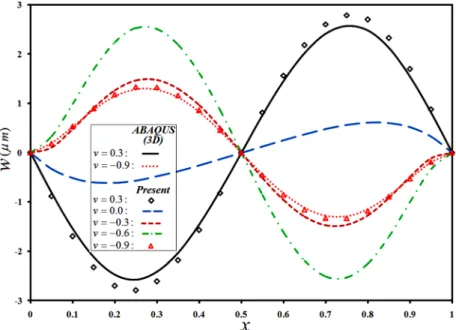
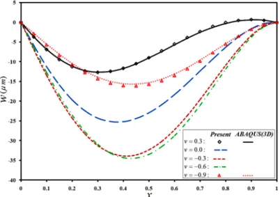
As Fig. 1 shows, a positive shear traction on the top layer induces a bending moment in the clockwise direction with respect to the lower layers; for this reason, an in-ward lateral deflection may be induced in the conical shell (or equivalently, a downward lateral deflection in the annular plate), as Fig. 2 (and later, Fig. 14) implies. In addition to the induced moment, the shear traction tends to move particles of the top layer of the shell/plate. Due the kinematic of deformation of the plate/shell and the constituted curvature, slopes of the lateral deflection curve becomes negative and positive at the inner/beginning and outer/end regions of the plate/shell, respectively. As the shear traction tends to move the top layer along the tangent to the deformed plate/shell; it tends to move the plate/shell downward/inwards in the vicinity of the smaller edge of the plate/shell (due to the negative slope) whereas it pushes the top layer upward/outwards (due to the positive slope), in the neighborhood of the larger edge of the annular plate or conical shell. When the Poisson ratio is positive, the plate/shell is more compliant; so that the plate/shell may experience a small up-ward/outward deflection in the neighborhood of the larger edge, as present and ABAQUS results of Fig. 2 (and later, Fig. 14) confirm. When material of the plate/shell is more auxetic, the plate/shell becomes stiffer; so that, the force effect of the shear traction diminishes in comparison to influence of the bending moment of the sections.
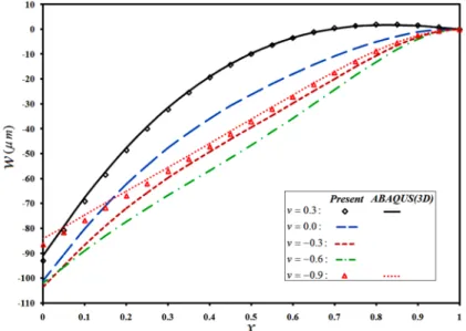
Figure 3: Effects of the auxeticity of the material on the radial distribution of the lateral deflection of the S-C annular plate, under shear traction.
Figure 4: Effects of the auxeticity of the material on the radial distribution of the lateral deflection of the F-C annular plate, under shear traction.
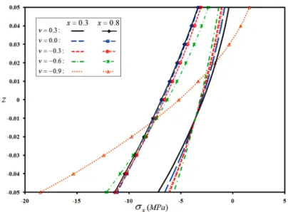
show that the shear traction has produced bending moments about the reference surface of the plate. However, since transverse distribution of the modulus of elasticity of the section is not uni-form, the resulting transverse distributions of the in-plane stress are non-linear. Results show an excellent concordance with the ABAQUS 3D-elasticity results.
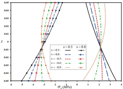
Figure 5: Effects of the auxeticity of the material on transverse distribution of the in-plane stress of the C-C annular plate, under shear traction.
Figure 7: Effects of the auxeticity of the material on transverse distribution of the in-plane stress of the F-C annular plate, under shear traction.
The displacement results obtained either by present research or from ABAQUS code (some of them are not reported here due to their coincidence with the presented analytical results) show that trends of variations of results are different for the n = -0.9,, 0 and n =0,, 0.3ranges of the Poisson ratio. On the other hand, the bending mechanism is quite different for the three types of boundary conditions, e.g., for the clamped-clamped and free-clamped plates. The stress results show that as the movability and therefore, rigidity of the plate increase, effects of the auxeticity of the material become more pronounced; so that results of the C-C and F-C plates exhibit respectively, the most and the least sensitivity to the auxeticity of the material. Furthermore, in contrast to the somewhat linear transverse distribution of the in-plane stress of the C-C and S-C plates in the neighborhood of the clamped edge, this distribution is remarkably distorted in the F-C plate.
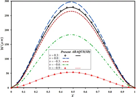
Axial distributions of the lateral deflection of the auxetic FGM cylindrical shell are plotted for the three types of the boundary conditions in Figs. 8 to 10, respectively. Since the resulting mo-ments due to the imposed shear traction, geometry, and boundary conditions are symmetric with respect to the mid-length section of the C-C shell, the inflection point has almost formed at that section of the cylindrical shell. As may be noted from Fig. 8, trends of variations of the axial distri-bution of the lateral deflection are different for the n = -0.9,, 0and n = 0,, 0.3ranges of the
F-C plate, the shear traction has brought about outwards movements in the neighborhood of the clamped edge but inwards movements of the shell particles in the vicinity of the free edge, for low Poisson ratios. The auxeticity of the material mixture has significantly affected the resulting curva-tures and the trend of the lateral deflections.
Figure 8: Influence of the auxeticity of the material on axial distribution of lateral deflection of a C-C cylindrical shell subjected to a shear traction.
Figure 10: Influence of the auxeticity of the material on axial distribution of lateral deflection of a F-C cylindrical shell subjected to a shear traction.
Figure 11: Influence of the auxeticity of the material on transverse distribution of the in-plane stress of a C-C cylindrical shell subjected to a shear traction.
ing complicated deformation and stress fields and their interactions with the negative Poisson ratio effects may not enable exactly predictions of trends of the variations. Some of the ABAQUS results are also included to confirm that the results are accurate enough.
Figure 12: Influence of the auxeticity of the material on transverse distribution of the in-plane stress of a S-C cylindrical shell subjected to a shear traction.
Figure 13: Influence of the auxeticity of the material on transverse distribution of the in-plane stress of a F-C cylindrical shell subjected to a shear traction.
initial clamped edge (retaining the zero slope condition) on the interior regions have decayed with a smaller rate, so that these effect last further and location of the maximum lateral deflection shifts toward the larger edge. However, for positive Poisson ratios, the larger lateral deflections have oc-curred in regions that are closer to the smaller edge. On the other hand, as Fig. 15 that has been plotted for the S-C conical shell implies, due to the difference in direction of the bending moment caused by the shear traction at x=0.3 and x=0.8, direction of the curvature of the shell is different in the mentioned sections. Fig. 16 reveals that the resulting curvatures become remarkably smaller at n= -0.9, as the previous cases.
Figure 14: Effects of the auxeticity of the material on meridian distribution of the lateral deflection of a C-C truncated conical shell subjected to a shear traction.
Figure 16: Effects of the auxeticity of the material on meridian distribution of the lateral deflection of a F-C truncated conical shell subjected to a shear traction.
Figure 17: Effects of the auxeticity of the material on transverse distribution of the in-plane stress of a C-C truncated conical shell subjected to a shear traction.
bending moment, the shear traction exerts compressive stresses on one of the considered sections and tensile stresses on the other, location of the neutral layer is not identical for the two sections, as may be inferred from Figs. 17 to 19. Since in contrast to the conventional materials, the auxeticity causes the material to shrink in all directions in compressive stresses and expand in all directions in tensile stresses (so that the cross section increases remarkably), the stress field varies in a compli-cated manner; so that the stresses have become less in the considered sections of the C-C conical shell in more negative Poisson ratios but increased significantly in the neighborhood of the simply supported and free edges of the S-C and F-C shells, respectively.
Figure 18: Effects of the auxeticity of the material on transverse distribution of the in-plane stress of a S-C truncated conical shell subjected to a shear traction.
4.2 Uniform Thickness FGM Shells/Plates Under Combined Shear and Normal Tractions
In the present section, responses of functionally graded auxecit shells/plates subjected to simultane-ous normal and shear tractions are studied. Each of these distinct tractions may have different in-teractions with the negative Poisson ratios. As the previous section, h/L ratio is equal to 0.1. To present a more useful discussion, transverse distribution of the in-plane displacement component of the plate is also investigated for the x/L=0.3 and 0.8 sections.
Radial distributions of the lateral deflection of the annular plate are shown in Figs. 20 to 22, for the three types of the boundary conditions, respectively. As before, trends of variations of the dis-tributions of the lateral deflection are different for the n = -0.9,, 0 and n = 0,, 0.3intervals of the Poisson ratio. However, the trends are more robust, since the transverse load has the dominant effects. Results related to the lower and higher limits of the Poisson ratio are also verified by the 3D elasticity results extracted from ABAQUS.
The transverse distribution of the in-plane stress of the C-C plate plotted in Fig. 23, show that location of the neutral layer is affected not only by the shear traction but also especially by the transverse load. Moreover, gradients of the distribution are higher in the neighborhood of the inter-nal edge.
Transverse distribution of the in-plane displacement component is depicted in Fig. 24. From this figure, one may deduce that both the extensional and bending rigidities increase drastically by employing higher negative Poisson ratios.
Figure 21: Effects of the auxeticity of the material on radial distribution of lateral deflection of a S-C annular plate subjected to combined shear and normal tractions.
Figure 23: Effects of the auxeticity of the material on transverse distribution of in-plane stress of a C-C annular plate subjected to combined shear and normal tractions.
Figure 24: Effects of the auxeticity of the material on transverse distribution of in-plane displacement of a C-C annular plate subjected to combined shear and normal tractions.
and extends influence of the edge condition on farther interior regions, this apparent maximum has vanished for higher negative Poisson ratios.
Fig. 28 reveals that in this case, transverse distribution of the in-plane stress manifests severe gradients in the neighborhood of the second edge of the shell that exaggerates at larger negative Poisson ratios. As the previous case, Fig. 29 that presents effects of the Poisson ration on transverse distribution of the in-plane displacement of the C-C shell, shows the significant growth in the bend-ing and extensive rigidities of the sections by increasbend-ing the auxeticity of the material mixture.
Figure 25: Axial distribution of lateral deflection of a C-C cylindrical shell subjected to combined shear and normal tractions, for various Poisson ratios.
Figure 27: Axial distribution of lateral deflection of a F-C cylindrical shell subjected to combined shear and normal tractions, for various Poisson ratios.
Figure 29: Transverse distribution of in-plane displacement component of a C-C cylindrical shell subjected to combined shear and normal tractions, for various Poisson ratios.
Figure 30: Meridian distribution of lateral deflection of a C-C truncated conical shell subjected to combined shear and normal tractions, for various Poisson ratios.
char-er than those of the cylindrical shell. Moreovchar-er, in the present situations, the latchar-eral deflection of free edge of the F-C shell becomes larger when more negative Poisson ratios are employed (Fig. 32). Indeed, in highly auxetic materials, the work consumed for establishment of the intermediate curva-tures in the shell is used for deformation of the free edge, due to the higher bending rigidity of the shell.
Figure 31: Meridian distribution of lateral deflection of a S-C truncated conical shell subjected to combined shear and normal tractions, for various Poisson ratios.
Figure 33: Transverse distribution of in-plane stress of a C-C truncated conical shell subjected to combined shear and normal tractions, for various Poisson ratios.
Figure 34: Transverse distribution of in-plane displacement of a C-C truncated conical shell subjected to combined shear and normal tractions, for various Poisson ratios.
4.3 Plates and Shells Under Non-Uniform Shear and Normal Tractions
This section is included merely to introduce some of capabilities of the proposed formulation. In this regard, a C-C type shell/plate of thickness ratio h/L=0.2 whose bottom section is subjected to normal and shear traction whose intensity varies according to = ˆ =
(
1+ + 2)
MPab
q T x x is
surfaces of a pipe or nozzle. Since the overall stress variations behavior is similar to those of the previous section, they are not reported here to avoid repetitive results. However, meridian/radial distribution of the lateral deflection of the annular plate as well as the conical and cylindrical shells are illustrated simultaneously in Fig. 35, for various values of the Poisson ratio. Since the higher tractions are imposed in the second half of the meridian coordinate region, location of the maximum lateral deflection has shifted toward that half, in comparison to the previous cases.
4.4 Plates and Shells with Variable Thickness and Various Boundary Conditions
Finally, simultaneous effects of the auxeticity of the material, thickness variability, and boundary conditions on distributions of the stresses and lateral deflections of the plate and shells are investi-gated. The shell/plate is subjected to a normal traction whose intensity is q =1MPa.
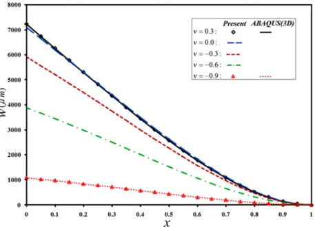
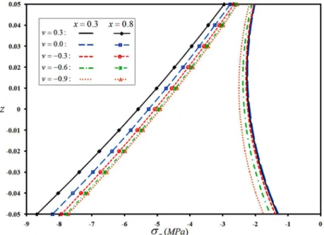
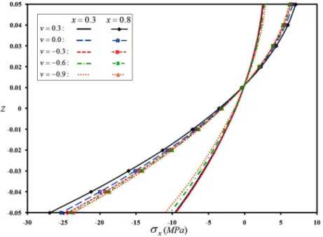
First, C-C type plates and shells with a linear variation of the thickness, hb = -0.05, 0.1ht = x are considered. Meridian/radial distributions of the lateral deflection of the plate and shells are plotted in Fig. 36, for various Poisson ratios. Transverse distribution of the in-plane stress of the annular plate and cylindrical and conical shells are depicted in Figs. 37 to 39, for three sections (x/L=0.3, 0.5, and 0.8) and ABAQUS verification of some of the results is included as well, for var-ious Poisson ratios. As before, lateral deflection of the cylindrical shell is larger; since for an identi-cal Rb radius, the cylindrical configuration is more impact (radii of the truncated conical shell are generally larger than Rb) and therefore, its rigidity is higher. Furthermore, since the thickness is greater at the second/exterior edge of the plate/shell, the maximum lateral deflection and the max-imum meridian stress have occurred in regions with more flexibility, i.e., those located in the neigh-borhood of the first/interior edge. Furthermore, due to the occurrence of inflection point whose location may be explored based on Fig. 36, bending direction of the cross section and consequently, sign of the stresses of the plate/shell has changed for the x/L=0.8 section.
Figure 36: Simultaneous effects of the auxeticity and linear thickness variability on meridian/radial distribution of the lateral deflection of the considered plates and shells.
Figure 38: Simultaneous effects of the auxeticity and linear thickness variability on transverse distribution of the axial stress of the C-C cylindrical shell.
Figure 39: Simultaneous effects of the auxeticity and linear thickness variability on transverse distribution of the meridian stress of the C-C truncated conical shell.
boundary conditions. The resulting distributions of the lateral deflection are plotted in Figs. 40 and 41, respectively. The previous conclusions are confirmed here once again; since the maximum deflec-tions have occurred in secdeflec-tions that are closer to the first/interior edge of the structure and rigidity of the plate/shell has increased drastically with the auxeticity.
Figure 40: Simultaneous effects of the auxeticity and parabolic thickness variability on meridian/radial distributions of the lateral deflection of the C-C plates and shells.
5 CONCLUSIONS
In the present research, a unified Taylor transform solution is presented for stress and displacement analysis of the variable thickness auxetic functionally graded conical and cylindrical shells and cir-cular/annular plates. The top or bottom layers of the shell/plate may be subjected to general non-uniform normal and shear tractions and the edges may be simply supported, clamped or free.
Some of the obtained practical results are:
Combination of the auxeticity of the functionally graded material, structure configuration, shear/normal tractions, thickness variability, and edge conditions leads to complicated and sometimes non-predictable behaviors.
The differences between results of the successive values of the Poisson ratio grow as the Pois-son ratio becomes more negative.
Trends of variations of the results are different for the n = -0.9,, 0 and n = 0,, 0.3 rang-es of the Poisson ratio.
Stress distributions of the C-C and F-C plates exhibit respectively, the most and the least sensitivity to the auxeticity of the material.
There are similarities between distributions of the lateral deflection and in-plane stress of the truncated conical shells, cylindrical shells, and annular plates, for the three types of the boundary conditions.
Results reveal that for the considered material properties, the overall lateral rigidity of the plate has grown to up to six to seven times, for n = -0.9, for all the C-C, S-C, and F-C boundary conditions.
Since the lateral stiffness is proportional to the inverse of (1-v2), the worst lateral stiffness of the annular plate and conical shell belongs ton = 0. This hint is confirmed by the results
as well.
In contrast to the lateral deflection results, more regular trends may be noted for the stress results, with varying the Poisson ratio.
Effects of the auxeticity on the in-plane stresses are more remarkable at sections with more flexibility (in the vicinity of the free or simply supported edges) and regions located at the neighborhood of the first edge.
For positive Poisson ratios, the larger lateral deflections have occurred in regions that are closer to the smaller edge.
The maximum deflections have occurred in sections that are closer to the first/interior edge of the structure. However, auxeticity of the material affects the resulting curvatures and loca-tion of the maximum lateral deflecloca-tion.
References
Abediokhchi, J., Shakouri, M., Kouchakzadeh, M.A. (2013). Bending analysis of moderately thick functionally grad-ed conical panels with various boundary conditions using GDQ method, Composite Structures 103: 68–74.
Aghdam, M.M., Shahmansouri, N., Bigdeli, K. (2011). Bending analysis of moderately thick functionally graded conical panels, Composite Structures 93: 1376–84.