Abstract
It is well recognized that size dependency of materials characteris-tics, i.e. size-effect, often plays a significant role in the perfor-mance of nano-structures. Herein, strain gradient continuum theo-ry is employed to investigate the size dependent pull-in instability of beam-type nano-electromechanical systems (NEMS). Two most common types of NEMS i.e. nano-bridge and nano-cantilever are considered. Effects of electrostatic field and dispersion forces i.e. Casimir and van der Waals (vdW) attractions have been consid-ered in the nonlinear governing equations of the systems. Two different solution methods including numerical and Rayleigh-Ritz have been employed to solve the constitutive differential equations of the system. Effect of dispersion forces, the size dependency and the importance of coupling between them on the instability per-formance are discussed.
Keywords
Strain gradient theory, Pull-in instability, cantilever, Nano-bridge, Dispersion forces, Size effect.
Modeling the size dependent pull-in instability of
beam-type NEMS using strain gradient theory
1 INTRODUCTION
Micro/nano-electromechanical systems (MEMS/NEMS) are increasingly used in various engineering and science branches i.e. mechanics, chemistry, optics, biology, electronics, etc.. Nowadays, these ultra-small systems are utilized in order to develop nano-devices like sensors, actuators, accelerome-ter, tweezers, switches, etc (Zhang et al., 2004). A beam-type NEMS is constructed from two con-ductive electrodes, which one of these electrodes is movable and the other one is fixed (grounded). Applying voltage difference between these components causes deflection of the movable one toward the fixed electrode. When the applied voltage exceeds its critical value, which is known as pull-in voltage, the pull-in instability occurs and the movable electrode suddenly adheres to the ground. The electromechanical pull-in instability of microsystems has been investigated by previous re-searchers during previous decades (Batra et al., 2006; 2008) neglecting nano-scale effects. However,
Ali Koochia H am id M . Sedighib M oham adreza Abadyana*
aShahrekord Branch, Islamic Azad University, Shahrekord, Iran bDepartment of Mechanical
Engineer-ing, Faculty of EngineerEngineer-ing, Shahid Chamran University of Ahvaz, Iran
Latin American Journal of Solids and Structures 11 (2014) 1806-1829
with decreasing the dimensions to sub-micron, the nano-scale phenomena should be considered in theoretical models. In this paper the effects of two important nano-scale phenomena on the pull-in instability of beam type nano-structures are investigated.
The first phenomenon which appears in nano scale distances is the presence of dispersion forces i.e. Casimir and van der Waals (vdW) force. In distance less than few micrometers, Casimir force significantly affects the nano-beams stability. Casimir force between two plates can be explained via electromagnetic quantum vacuum fluctuations and motion of virtual photons between two con-ductive surfaces (Lifshitz, 1956) .In recent years, various approaches such as experimental meas-urements (Buks et al., 2001a; 2001b), using finite element methods (Moghimi Zand et al., 2010;Tadi Beni et al., 2013), experimental observations (Wilson and Beck, 1996; Sundararajan and Bhushan, 2002), applying classic continuum theory (Ramezani et al., 2008; 2007;Farrokhabadi et al., 2013; Tadi Beni et al., 2011), semi-analytical approaches (Noghrehabadi et al., 2011;Koochi and Abadyan 2011; Duan et al., 2013) are utilized to investigate the effect of Casimir force on performance of nano-systems. Another dispersion force that is dominant in nano-scales is the vdW force that affects the stability of nano-structures. If the separation between the interacting bodies is typically less than few nanometers, the retardation effect is negligible and the nano-scale interaction can be mod-eled as vdW attraction. The pull-in instability of NEMS in the presence of vdW attraction was studied by previous researchers (Kolpekwar et al., 1998; Rotkin, 2002; Lin and Zhao, 2003; Abdi et al., 2011; Soroush et al., 2012; Dequesnes et al., 2002) using various approaches
The second phenomenon in nano-scale is size dependency of the mechanical performance of nano-structures. Experimental observations indicate that elastic characteristics of materials highly are affected by the dimensions and are size dependent (Fleck et al., 1994; Stolken and Evans, 1998). It has been shown that torsional hardening of copper wire increases by a factor of 3 as the wire diameter decreases from 170 to 12 μm (Fleck et al. 1994). Stolken and Evans (1998) showed that decrease in thickness of thin nickel beams from 50 to 12.5 μm can lead to great increase in the plas-tic work hardening of the constitutive material. Other measurements evaluate the material length scale parameter of single crystal and polycrystalline copper to be 12 and 5.84 μm, respective-ly(McElhaney et al., 1998; Nix and Gao, 1998). Also, the size-dependent behavior has been detected in some kinds of polymers (Chong and Lam, 1999). For hardness measurement of bulk gold, it is found that the plastic length scale parameter (for indentation test and hardness behavior) of Au increases from 470 nm to 1.05 μm with increasing the Au film thickness from 500 nm to 2 μm (Cao
et al., 2007). Based on test results gathered via microhardness test, the plastic length scale
Latin American Journal of Solids and Structures 11 (2014) 1806-1829
as to balance the dimensions of strains (ε) and strain gradients (dε/dx) (Wang et al., 2003). As the characteristic length of the deformation field becomes significantly larger than the material length scale parameter, strain gradient effects become negligible because the strain terms are much larger than their scaled gradient terms (Wang et al., 2003).
In this regards, the non-classical theories such as non-local elasticity(Eringen and Edelen 1972), couple stress theory (Kong, 2013; Ejike, 1969), strain gradient theory (Lam et al., 2003), modified couple stress theory (Yang et al., 2002) etc. have been developed to consider the size effect in theo-retical continuum models. One of the pioneering works in modeling the size-dependent behavior of micro-structures was conducted by Cosserat, in the beginning of 20th century (Cosserat and Cosse-rat, 1909). Afterwards more general continuum theories have been developed by Toupin (1962), Koiter (1964) and Mindlin (1964) for linear elastic materials in which gradients of normal strains were included and additional material length scale parameters were therefore added as well as Lame constants. The first strain gradient theory was introduced by Mindlin and Eshel (1968) in which the potential energy-density assumed to be depended on the gradient of stain as well as strain. The most comprehensive work was done by Mindlin[14] which contained five additional material param-eters and encompassed other non-local theories as special cases Non-local elasticity has been used to study buckling, bending vibration dislocation mechanics, fracture mechanics, surface tension fluids, etc. (Reddy, 2007; Mohammadi et al, 2012; 2013; Moosavi et al, 2011; Danesh et al, 2012; Faraj-pour et al, 2012)
Lam et al. (2003), introduced a modified strain gradient theory with three material length scale parameters relevant to dilatation gradient, deviatoric gradient, and symmetric rotation gradient tensors. While some simple size dependent models based on modified couple stress theory have been applied to analyze the pull-in instability of MEMS/NEMS (Tadi Beni et al., 2011; HRokni, et al., 2013; Noghrehabadi et al., 2013; Zhang and Fu, 2012; Mindlin and Tiersten, 1962; Dequesnes et al., 2002; Yin et al., 2011), only rare works have utilized strain gradient theory for analyzing. One of the first works in this field has been conducted by Wang et al. (2011a) who modeled the size-dependent instability of clamped structure using strain gradient elasticity theory. However they have not considered the effect of nano-scale attractions such as Casimir and vdW force in their models. In other works (Wang et al., 2011b; 2012) the pull-in instability of rectangular and circular plate MEMS has been investigated. Dynamic pull-in instability and free vibration characteristics of circular microplates subjected to the combined hydrostatic and electrostatic forces are investigated in refs. (Ansari et al., 2013; Mohammadi et al., 2013). However, it should be noted that none of the above mentioned works has taken the important effect of nano-scale forces into account.
Latin American Journal of Solids and Structures 11 (2014) 1806-1829
2. THEORETICAL MODEL
2.1. Fundamentals of strain gradient theory
In strain gradient theory in spite of whatever was stated in classic mechanic, equations contain a parameter which introduced as length scale parameter that has statistical nature and indicates that material behavior is depending on material dimensions in micrometer scale. Should be noted that in absence of length scale parameters, the obtained equation of strain gradient theory are turned to the same equations presented in classic mechanic.
Regarding the strain gradient theory modified and suggested by Lam et al. (2003), U stored strain
energy density in the linear elastic and isotropic material with small deformation is written as fol-lows:
U=1
2 !ij!ij+pi!i+!ijk (1)
!ijk(1)+mijs!ijs
(
)
, (1)in which
(2)
!ij=1 2
u
i,j+u
j,i
(
)
(3) !i="mm,i
(4) !ijk(1)=1
3
(
"jk,i+"ki,j+"ij,k)
! 115#ij
(
"mm,k+2"mk,m)
! 115"##jk
(
"mm,i+2"mi,m)
+#ki(
"mm,j+2"mj,m)
$ %(5) !ijs =1
2ejklul,ki In above equations, ui, gi,
(1)
ijk h , s
ij
c , dijandeijk indicate components of displacement vector,
dilata-tion gradient vector, deviatoric stretch gradient tensor, symmetric rotadilata-tion gradient tensor, Kronocker delta and permutation symbol, respectively. Also
ij
s , pi, (1) ijk
t , mijs , are components of
Cauchy’s stress and high order stress tensors, respectively that are identified as the follows (Lam, et al., 2003):
(6)
!ij=2µ "ij+ #
1!2#"mm$ij "
#
$ %
& '
(7)
pi=2µl0 2 !i
(8) !ijk
(1)
=2µl12"ijk(1)
(9)
mijs =2µl22!ijs
In the above equations, ν and μ are Poisson’s ratio and shear modulus, respectively. Also l0, l1and l2
Latin American Journal of Solids and Structures 11 (2014) 1806-1829 2.2. Nonlinear constitutive equation
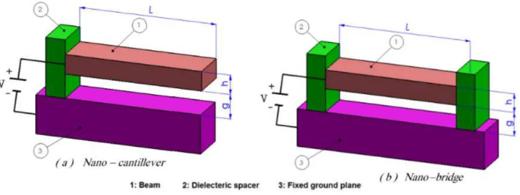
Figures (1a) and (1b) show schematic representation of beam-type nano-cantilever and double clamped nano-beam (nano-bridge) that is applied in electromechanical structures such as actuators, respectively. Herein, the nano-structures with a beam length of L, wide of b and thickness of h are considered.
Figure 1: Schematic representations of (a) nano-cantilever and (b) nano-bridge.
2.2.1. Strain energy
The total strain energy, U, for a deformed Euler–Bernoulli beam is given by:
(10) U=Ubending+Ustretching
where, Ustretching and Ubending are energy stored in the beam due to axial forces and bending strain,
respectively.
In this work, the displacement field of Euler-Bernoulli beam theory is applied for modeling the elastic behavior of the nano-structures. Based on this theory, the displacement field can be written as the following:
(11) u
1=!Z
"W
"X u
2=0 u3=W X
( )
The variable, W, indicates beam displacement in direction of Z axis. Substituting the linear dis-placement field of equation (11) in equations (1)-(9), after some elaborations the bending strain energy is obtained as the following
(12)
Ubending= U dV=
V
!
12 EI+2µAl02+ 815µA
l12+µAl22 "
#
$ %
& ' d
2 W dX2 "
# $$ %
& '' 2
+A 2µl02+4
5µ
l12 "
#
$ %
& ' d
3 W dX3 "
# $$ %
& '' 2 (
) * *
+
, -0
L
!
dXIn above equation, I is the second cross section moment around Y axis.
Now, the stretching energy stored in the beam due to axial forces can be written as
(13) Ustretching=1
2 Fa
dW dX ! "
# $
% & 2
dX 0
Latin American Journal of Solids and Structures 11 (2014) 1806-1829
In the above equation, Fa is the axial resultant force associated with the mid-plane stretching (in
the absence of external axial force, thermal stress, etc.). Note that there is no axial stretching (Fa=0) for nano-cantilever due to the movability of the free end and therefore the amount of energy
Ustretching equals zero. In the case of nano-bridge, axial force associated with the mid-plane
stretch-ing (Fa) should be contributed in the total energy. When nano-beam is in tension, the actual beam
length L′ will become longer than the original length L. However, the beam is immovable in the Z-
and X-directions at both ends of the nano-bridge. Thus, an additional axial force will occur and can be expressed as:
(14) Fa=EA
L !
L "L
(
)
=EA2L dW
#X $ % & '
( )
2
dX
0
L
*
2.2.2. Work of external forces
Considering the distribution of external forces per unit length of the beam (fexternal), the work by
these external forces can be obtained as:
(15)
Vexternal= fexternalW 0
L
!
(X)dXNow, by Considering the first order fringing field correctness effect the electrostatic force per unit length of the beam is written as the following (Ramezani et al., 2008):
(16)
felec=
!0bV2
2
(
g!W(X))
21+0.65
(
g!W X( )
)
b"
# $ $
%
& ' '
In the above equation ε0= 8.854×10⁻¹² c2 N-1m-2 is the permittivity of vacuum. V is external voltage
applied to nano-actuator and g is initial distance between ground and movable electrodes.
The dispersion forces per unit length of the beam (fdisp) are defined considering the van der Waals
and Casimir forces. Based on what is mentioned in section 1, two interaction regimes can be de-fined: first, the large separation regime in which the Casimir force is dominant (typically above several tens of nanometers (Israelachvili and Tabor, 1972; Klimchitskaya et al., 2000; Bostrom and Sernelius, 2000)). Considering the ideal case, the Casimir interaction is proportional to the inverse fourth power of the separation (Gusso and Delben, 2008):
(17)
fCas= !
2 !cb
240
(
g!W X( )
)
4where !=1.055!10"34Js is Planck’s constant divided by 2π and c=2.998×10^8 m/s is the light speed.
Latin American Journal of Solids and Structures 11 (2014) 1806-1829
fvdW = Ab
6!(g!W(X))
3 (18)
where A is the Hamaker constant.
Finally total energy of system can be summarized as:
!=1
2
EI+2µAl
0 2 + 8 15µ Al 1 2 +µAl
2 2 " # $ % & ' d 2W dX2 " # $$ % & '' 2
+A 2µl 0
2 +4
5µl1
2 " # $ % & ' d 3W dX3 " # $$ % & '' 2 ( ) * * + , -0 L
.
dX +1 2 F a dW dX " # $ % & ' 2 dX 0 L.
/ fexternalW0
L
.
(X)dX(19)
Now, by using the substitutions x=X/L and w=W/g the nondimentional total energy can be ex-plained as:
!=1
2 1+
µs 15 30 l0 l2 " # $ % & ' 2
+8 l1
l2 " # $ % & ' 2 +15 " # $ $ % & ' ' " # $ $ % & ' '
d2w
dx2 " # $$ % & '' 2
+ µs 30
( )
! 2 5l0 l2 " # $ % & ' 2
+2 l1
l2 " # $ % & ' 2 " # $ $ % & ' '
d3w
dx3 " # $$ % & '' 2 ( ) * * + , -0 1
.
dx +1 2 ! dw dx( )
2dx 0 1 . ( )* + ,-dw dx " # $ % & ' 2 dx 0 1
.
/ !n(1/w)n+ !2
(1/w)2(1+0.65!(1/
w)) " # $$ % & ''w 0 L
.
(x)dx(20)
where the dimensionless parameters are identified as:
(21a) !n=
AbL4
6"g4EI vdW interaction (n = 3)
"2!cbL4
240g5EI Casimir interaction (n = 4) ! " # # $ # # (21b)
!=V "0bL 4
2g3EI
(21c)
!=g
b
(21d)
µs
= 12µ
E h l
2
(
)
2(21e)
!=L
h
(21f)
!
=
6
Latin American Journal of Solids and Structures 11 (2014) 1806-1829
In above relations, β, μs and αn interpret the dimensionless values of applied voltage, size-effect and
dispersion forces.
3. SOLUTION METHODS 3.1. Rayleigh–Ritz method
To solve the governing equation of the systems, the displacement is expressed as a linear combina-tion of a complete set of linearly independent basis funccombina-tions φi(x) in the form of:
w x
( )
= qi!i( )
x i=1n
! (22)
where the index i refers to the number of modes included in the simulation. We use the linear mode shapes of the nano-beam (based on classic continuum theory) as basic functions in the Rayleigh– Ritz procedure. The classic mode shapes of cantilever nano-beam can be expressed as:
!i
( )
! =cosh(
!i!)
!cos(
!i!)
!cosh
( )
!i !cos( )
!isinh
( )
!i !sin( )
!isinh
(
!i!)
!sin(
!i!)
(
)
(23)where λi is the ith root of characteristic equation of free (for nano-cantilever) or
clamped-clamped (for nano-bridge) beams. Considering the equilibrium of the system, one can write:
!" !qi =
0 i=0,1,...,N (24)
This led to a system of algebraic equation which can be solved numerically to obtain the final solu-tion. Using Taylor expansion for electrostatic and dispersion force, substituting (20) and (22) into (24), assuming the orthogonality of φi(x) and then following some straightforward mathematical
elaborations a system of algebraic equation can be fined as:
1
+
µ
s
15
30
l
0
l
2
!
"
#
#
$
%
&
&
2
+
8
l
1
l
2
!
"
#
#
$
%
&
&
2
+
15
!
"
#
#
#
$
%
&
&
&
'
(
)
)
)
*
+
,
,
,
!
i
4
q
i
-µ
s
30
( )
!
2
5
l
0
l
2
!
"
#
#
$
%
&
&
2
+
2
l
1
l
2
!
"
#
#
$
%
&
&
2
'
(
)
)
)
*
+
,
,
,
"
i
0
1
.
q
j
j
=
1
N
/
d
6
"
j
dx
6
dx
-
#
.
0
1
"
i
q
j
d"
j
dx
j
=
1
N
/
!
"
#
#
$
%
&
&
2
dx
0
1
.
'
(
)
)
)
*
+
,
,
,
q
j
j
=
1
N
/
d
2
"
j
dx
2
0
1
2
3
2
4
5
2
6
2
dx
-
"
i
A
k
(
q
j
"
j
)
k
j
=
1
N
/
k
=
0
7
/
0
1
.
dx
+
B
.
C
.
=
0
i
=
1, 2,..,
N
(25)
where N is the number of considered terms of Rayleigh–Ritz and Ak is the Taylor expansion
Latin American Journal of Solids and Structures 11 (2014) 1806-1829
B.C.= µs 30
( )
! 25 l0 l2 ! " # # $ % & & 2
+2 l1 l2 ! " # # $ % & & 2 ! " # # # $ % & &
& qj d3
dX3
!j
j=1 N ' ! " # # $ % & &
d2!i
dX2 x=1
( µs
30
( )
" 2 5 l0l2 ! " # # $ % & & 2
+2 l1 l2 ! " # # $ % & & 2 ! " # # # $ % & & & qj
d3
dX3
!
j j=1
N ' ! " # # $ % & &
d2!i
dX2 x=0
+ µs
30
( )
" 2 5 l0l2 ! " # # $ % & & 2
+2 l1 l2 ! " # # $ % & & 2 ! " # # # $ % & & & qj
d5
dX5
!j
j=1 N ' ! " # # $ % & &!i
x=1
( µs
30
( )
" 2 5 l0l2 ! " # # $ % & & 2
+2 l1 l2 ! " # # $ % & & 2 ! " # # # $ % & & & qj
d4
dX4
!j
j=1 N ' ! " # # $ % & & d! i dX
x=1
(26)
for nano-cantilever and:
B.C.= µs 30
( )
! 25 l0
l2
!
"
##
$
%
&&
2+2 l1
l2
!
"
##
$
%
&&
2!
"
#
##
$
%
&
&&
d3 dX3 qj!j j=1
N '
!
"
#
#
$
%
&
&
d2!
i
dX2 x=1
( µs 30
( )
" 25 l0
l2
!
"
##
$
%
&&
2+2 l1
l2
!
"
##
$
%
&&
2!
"
#
##
$
%
&
&&
d 3 dX3 qj!j j=1
N '
!
"
#
#
$
%
&
&
d2!
i
dX2 x=0
(27)
for nano-bridge.
The Maple commercial software is employed to numerically solve the system of algebraic equations.
3.2. Numerical method
In addition with the Rayleigh–Ritz method, the deflection of the nano-structures is numerically simulated and the results are compared with those of Rayleigh–Ritz method. Utilizing Hamilton principle i.e.
δ
( )
П =0, in which δ indicates variations symbol, the governing equation of lateraldeflection of the system can be derived as the following
(28)
1+
µ
s15
30
l
0l
2!
"
#
$
%
&
2+
8
l
1l
2!
"
#
$
%
&
2+
15
!
"
#
#
$
%
&
&
'
(
)
)
*
+
,
,
-
4w
-
x
4.
µ
s30
( )
!
25
l
0l
2!
"
#
$
%
&
2+
2
l
1l
2!
"
#
$
%
&
2!
"
#
#
$
%
&
&
-
6w
-
x
6=
"
n(1
.
w
)
n+
#
2
(1
.
w
)
2(1
Latin American Journal of Solids and Structures 11 (2014) 1806-1829
following boundary conditions of nano- cantilever is:
w
( )
0 =dw dx0
( )
=d3 w
dx3 0
( )
=01+µs
15 30 l 0 l 2 ! " # # $ % & & 2 +8 l 1 l 2 ! " # # $ % & & 2 +15 ! " # # # $ % & & & ' ( ) ) ) * + , , ,
d3w
dx3 1
( )
- µs30
( )
! 2 5 l 0 l 2 ! " # # $ % & & 2 +2 l 1 l 2 ! " # # $ % & & 2 ! " # # # $ % & & &d5w
dx5 1
( )
=01+µs 15 30 l 0 l 2 ! " # # $ % & & 2 +8 l 1 l 2 ! " # # $ % & & 2 +15 ! " # # # $ % & & & ' ( ) ) ) * + , , ,
d2w
dx2 1
( )
- µs30
( )
! 2 5 l 0 l 2 ! " # # $ % & & 2 +2 l 1 l 2 ! " # # $ % & & 2 ! " # # # $ % & & &d4w
dx4 1
( )
=0d3w
dx3 1
( )
=0(29)
Similarly for nano-bridge by using Eq. 21 the governing equation is obtained as:
(30) 1+µs
15 30 l 0 l 2 ! " # # $ % & & 2 +8 l 1 l 2 ! " # # $ % & & 2 +15 ! " # # # $ % & & & ' ( ) ) ) * + , , ,
-4w -x4
. µs
30
( )
! 25 l 0 l 2 ! " # # $ % & & 2 +2 l 1 l 2 ! " # # $ % & & 2 ! " # # # $ % & & &
-6w -x6
." -w -x ! " # $ % & 2 dx 0 1 / ' ( ) ) * + , ,
d2w
dx2 =
#n
(1.w)n
+ $
2
(1.w)2
(1+0.65%(1.w))
And the following boundary conditions
w
( )
0 =dwdX
0
( )
=d3
w
dX3
0
( )
=0w
( )
1 =dwdX
1
( )
=d3
w
dX3
1
( )
=0(31)
The nonlinear governing differential equation is solved with the boundary value problem solver of MAPLE commercial software (For nano-bridge, an iterative procedure is required to solve the in-tegro-differential equation). The step size of the parameter variation is chosen based on the sensitiv-ity of the parameter to the maximum deflection (tip deflection for nano-cantilever and mid-length deflection for nano-bridge. The pull-in parameters are determined via the slope of the w-β graphs. It should be noted that the governing equation of the structures based on the classical theory is achieved by setting the l0, l1 and l2 equal to zero. In addition, the size-dependent behavior of
nano-beam based on the modified couple stress theory can be obtained by considering l0=l1=0 and l2=l
Latin American Journal of Solids and Structures 11 (2014) 1806-1829 3.3. Validation
To validate the Rayleigh–Ritz method and check the convergence rate of series, effect of increasing the number of modes on the pull-in deflection and voltage of a typical cantilever nano-actuator with αn=0.5, γ=0.4, h/l2=3, λ=20 and l0=l1=l1 are presented in Table 1. This table reveals the
conver-gence of the series with increasing the number of modes. By selecting three modes, an acceptable error is achieved.
Rayleigh–Ritz Method
Numerical 1 Term 2 Terms 3 Terms
βPI 1.97 2.03 2.04 2.05
Error(%) -3.90 -0.98 -0.48 - wPI(x=1) 0.4565 0.4384 0.4336 0.4305 Error(%) 6.039 1.835 0.720 -
Table 1: The convergence check of Rayleigh–Ritz
4. RESULT AND DISCUSSION
A typical nano-actuator with the geometrical characteristics of η=24, g/h=2, λ=25 and γ=g/b=0.1 are considered. The Young’s modulus E, and shear modulus μ are 169 GPa and 65.8 GPa, respec-tively.
4.1. NEMS deflection and pull-in instability
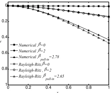
Latin American Journal of Solids and Structures 11 (2014) 1806-1829 Figure 2: Deflection of typical nano-cantilever for different values of applied voltage from zeroto pull in voltage
considering the Casimirforce (a4= 0.25).
Figure 3: Deflection of typical nano-bridge for different values of applied voltage from zero to pull-in voltage considering vdW force (a3= 5).
The dimensionless material length scale parameters l0/l2, l1/l2 and h/l2 values for both
nano-structures are selected as 1, 1 and 2, respectively. As seen, increasing the applied voltage increase the deflection of the nano-beams. When the applied voltage exceeds its critical value, βPI, then no
solution exists and the pull-in instability occurs. From the mathematical point of view, the
instabil-0 0.2 0.4 0.6 0.8 1
0
0.2
0.4
0.6
0.8
1
x w
Numerical ,β=0 Numerical ,β=2 Numerical ,β
pull-in=2.78 Rayleigh-Ritz,β=0 Rayleigh-Ritz , β=2 Rayleigh-Ritz ,β
pull-in=2.65
0 0.2 0.4 0.6 0.8 1
0
0.2
0.4
0.6
0.8
1
x w
Numerical ,β=0 Numerical ,β=15 Numerical ,βpull-in=19.28
Rayleigh-Ritz,β=0 Rayleigh-Ritz ,βpull-in=15
Latin American Journal of Solids and Structures 11 (2014) 1806-1829
ity occurs when 2
( 1) / 0
dw x= db Æ for nano-cantilever and dw x( = 0.5) /db2Æ 0 for
nano-bridge. The instability parameters of the system can be determined via the slope of the w-β graphs by plotting w vs.β.
Note that the operation distance of the nano-systems is limited by the pull-in instability. It is shown that the results of Rayleigh–Ritz method are in good agreement with those of numerical method. The relative error of presented methods with respect to the numerical solution is within the acceptable range for most engineering applications.
4.2. Influence of size effect
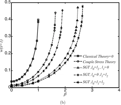
Figures 4 and 5 show the variation of normalized maximum tip deflection of the structures when the applied voltage increases from zero to pull-in value. Figure 4 corresponds to typical nano-cantilever operated in Casimir regime (α4=0.25) and Figure 5 corresponds to a nano-bridge operated
in vdW regime (α3=5).The results are calculated using three different theories i.e. size-independent
classical theory (l0=l1=l2=0), the modified couple stress theory (l0=l1=0 and l2=l) and strain
gradi-ent theory. The thickness of the nano-beams is selected twice of length scale parameter (h/l=2). These figures reveal that for a given applied voltage, the deflection value determined by classic the-ory is greater than those predicted by strain gradient thethe-ory and modified couple stress thethe-ory. In other word, size effect results in a hardening behavior of the structures. These figures demonstrate that in the strain gradient theory, the hardening effect of l0 is more pronounced than l1.
Figures 4and 5 also reveal that the nano-beam has an initial deflection due to the presence of at-tractive dispersion forces even, when no voltage is applied (β=0).
(a)
0 1 2 3 4
0 0.1 0.2 0.3 0.4 0.5
w(x
=
1)
β
Classical Theory=0 Couple Stress Theory SGT ,l0=l2 , l1=0
SGT, l0=0 ,l1=l2
Latin American Journal of Solids and Structures 11 (2014) 1806-1829 (b)
Figure 4: The variation of nano-cantilever tip displacement versus applied voltage parameter (Casimirregime: a4= 0.25) determined via different continuum theories(a) Numerical (b) Rayleigh-Ritz
0 1 2 3 4
0 0.1 0.2 0.3 0.4 0.5
w(x
=
1)
β
Classical Theory=0 Couple Stress Theory SGT ,l0=l2 , l1=0
SGT, l0=0 ,l1=l2
Latin American Journal of Solids and Structures 11 (2014) 1806-1829 (a)
(b)
Figure 5: The variation of nano-bridge mid-length displacement versus applied voltage parameter (vdW regime:a3= 5) determined via different continuum theories: (a) Numerical (b) Rayleigh-Ritz
4.3. Coupling between size effect and dispersion forces
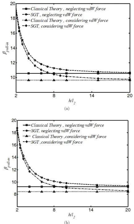
In nano-scale, both dispersion forces and size effect are significant. Variation of the pull-in voltage (βPI) of the nano-beams is demonstrated in Figures 6 and 7 as a function of the nano-scale
parame-ter (h/l2). Figure 6 presents the results for nano-cantilever that operates in Casimir regime and
Figure 7 corresponds to the nano-bridge operates in vdW regime. The horizontal lines correspond to the pull-in voltage (βPI) when no size effect has been considered (i.e. classical theory). These figures
0 5 10 15 20
0 0.1 0.2 0.3 0.4 0.5 0.6
w(x
=
0.5)
β
Classical Theory=0 Couple Stress Theory SGT ,l
0=l2 , l1=0 SGT, l
0=0 ,l1=l2 SGT ,l
0=l1=l2
0 5 10 15 20
0 0.1 0.2 0.3 0.4 0.5
w(x
=
0.5)
β Classical Theory=0 Couple Stress Theory SGT ,l
0=l2 , l1=0 SGT, l
0=0 ,l1=l2 SGT ,l
Latin American Journal of Solids and Structures 11 (2014) 1806-1829
show that dispersion forces decrease the pull-in voltage of system. Moreover, without considering dispersion force (αn=0), decreasing h/l2 results in decreasing the βPI of nano-systems. It should be
noted that decrease in h/l2 value corresponds to increase in size effect. This means size effect
pro-vides a hardening behavior that enhances the elastic resistance and consequent pull-in voltage of the nano-devices. On the other hand, with increase in the beam thickness, results of strain gradient theory approaches to those of classic continuum theory i.e. enhancing the beam thickness decreases the size-effect. This trend is also observed in the presence of dispersion forces where the pull-in voltage increases with increasing the size-effect.
(a)
(b)
Latin American Journal of Solids and Structures 11 (2014) 1806-1829 (a)
(b)
Figure 7: Influence of Size effect on pull-in voltage ofnano-bridge considering vdW regime (a3= 10). (a) Numerical (b) Rayleigh-Ritz.
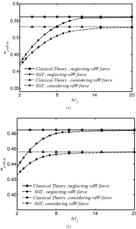
Figures 8 and 9 represent the influence of size effect (h/l2) on the instability deflection (wPI) of the
nano-cantilever and nano-bridge, respectively. Figure 8 shows that in the absence of dispersion force (α4=0), the pull-in deflection of nano-cantilever is independent of length scale parameter (h/l2).
However, as seen from figure 9 in the absence of dispersion force (α3=0), the pull-in deflection of a
Latin American Journal of Solids and Structures 11 (2014) 1806-1829
8, the pull-in deflection of nano-cantilever in the presence of dispersion force increases with increase in size effect Note that this trend is different from what observed for nano-bridge in the presence of dispersion force (α3=10), where wPI decreases with increasing in size effect.
(a)
(b)
Latin American Journal of Solids and Structures 11 (2014) 1806-1829 (a)
(b)
Latin American Journal of Solids and Structures 11 (2014) 1806-1829 4.4. Comparison with literature
To evaluate the model and compare with the literature, the deflection-voltage graphs for typical structures have been simulated in this subsection. The geometrical characteristics of the nano-actuator i.e. width, thickness and initial gap are 8000, 340 and 1019 nm, respectively (Sadeghian et al., 2009). Furthermore, the Young’s modulus E and Poison’s ratio ν are 169 GPa and 0.064, re-spectively ((Sadeghian et al., 2009). Figures 10 compares the pull-in voltages evaluated by the mod-ified strain gradient theory with the results of the classical theory and also the experimental obser-vations reported by Sadeghian et al. (2009) for nano-cantilever. With l = 38 nm, the best fit for the modified strain gradient theory and the experimental results is achieved for the considered beams. As seen, the strain gradient is reliable to predict pull-in voltage of electromechanical systems. Re-sults of present study show that the coupling of size effect and dispersion force is a crucial issue to precise determining the pull-in parameters of the nano-structures and should be included in theoret-ical models.
Figure 10: Comparison between experimental (Sadeghian et al., 2009) measurements with predictions of classical continuum and strain gradient theory for cantilever MEMS.
5. CONCLUSION
In this article, strain gradient theory has been employed to investigate the influence of size-effect on pull-in performance of nano-beams, incorporating the effect of dispersion force. The nonlinear gov-erning equation was solved using two different approaches, i.e. Rayleigh-Ritz method and numerical solution. Comparison between solving methods reveals that Rayleigh-Ritz method is in good agree-ment with numerical solution. It is found that:
20 30 40 50 60 70 0
5 10 15 20 25 30
Experimental SGT
Classical Theory VP
I
(V
o
lt
)
Latin American Journal of Solids and Structures 11 (2014) 1806-1829
• The presence of dispersion force reduces the pull-in voltage of the system. This nano-scale
force induces an initial deflection in freestanding nano-structures and reduces the pull-in de-flection of the nano-bridges and nano-cantilevers.
• Size-effect provides a stiffness behavior on electromechanical response of the nano- devices. The size effect increases the pull-in voltage of nano-actuator due to the stiffness effect.
• In small sizes of beam thickness, as this size can be compared with material length size, there
are a substantial difference between the results of classic continuum theory and those of strain gradient and modified couple stress theories.
• In absence of vdW force in nano-bridge, the pull-in voltage increases but deflection decreases with increase in size effect. While for nano-cantilever in absence of Casimir force, pull-in voltage increases but deflection does not change with increase in size effect parameter.
• In the presence of dispersion forces, pull-in voltage of the nano-bridge increases with
increas-ing the size effect. Interestincreas-ingly, increasincreas-ing the size effect decreases the pull-in deflection of the nano-bridge. However, for nano-cantilever (in the presence of dispersion force), both pull-in voltage and deflection increase with increase in size effect parameter.
References
Abdi, J., Koochi, A., Kazemi, A. S., Abadyan, M. (2011) Modeling the effects of size dependency and dispersion forces on the pull-in instability of electrostatic cantilever NEMS using modified couple stress theory. Smart Materials and Structures 20: 055011 (9 pp).
Al-Rub, R. K. A., and Voyiadjis, G. Z. (2004) Determination of the Material Intrinsic Length Scale of Gradient Plasticity Theory. Int. J. Multiscale Comput. Eng. 2(3):377-400.
Ansari, R., Gholami, R., Mohammadi, V., Faghih Shojaei, M. (2013) Size-Dependent Pull-In
Batra, R.C., Porfiri, M., Spinello, D. (2006) Capacitance estimate for electrostatically actuated narrow microbeams, Micro and Nano Letters 1:71–73.
Batra, R.C., Porfiri, M., Spinello, D. (2008) Reduced-order models for microelectromechanical rectangular and circu-lar plates incorporating the Casimir force. International Journal of Solids and Structures 45:3558–3583.
Bostrom, M. and Sernelius, B. E. (2000) Fractional van der Waals interaction between thin metallic films. Physical Review B 61:2204-2210
Buks, E., and Roukes, M.L. (2001) Metastability and the Casimir effect in micromechanical systems. Europhysics Letters 54:220–226.
Buks, E., and Roukes, M.L. (2001) Stiction, adhesion energy, and the Casimir effect in micromechanical systems. Physical Review B 63:033402.
Cao, Y., Nankivil, D. D., Allameh, S., Soboyejo W. O. (2007) Mechanical Properties of Au Films on Silicon Sub-strates. Mater. Manuf. Process 22: 187–194,
Chong, A.C.M. and Lam, D.C.C. 1999. Strain gradient plasticity effect in indentation hardness of polymers. J. Ma-ter. Res. 14(10):4103-4110
Cosserat, E., Cosserat, F. (1909) Theorie des Corps Deformables, Hermann et Fils, Paris.
Danesh M., Farajpour A., Mohammadi M. (2012) Axial vibration analysis of a tapered nanorod based on nonlocal elasticity theory and differential quadrature method, Mechanics Research Communications 39: 23– 27.
Latin American Journal of Solids and Structures 11 (2014) 1806-1829 Dequesnes, M., Rotkin, S. V., Aluru, N. R. (2002) Calculation of Pull-in Voltage for Carbon-Nanotube-Based Nanoe-lectromechanical Switches. Nanotechnology 13: 120–131.
Duan, J. S. , Rach, R., Wazwaz, A. M. (2013) Solution of the model of beam-type micro- and nano-scale electrostatic actuators by a new modified Adomian decomposition method for nonlinear boundary value problems. International Journal of Non-Linear Mechanics 49:159–169
Ejike U.B.C.O. (1969) The plane circular crack problem in the linearized couple-stress theory, International Journal of Engineering Science 7:947–961.
Eringen, A.C. and Edelen D.B.G. (1972) On nonlocal elasticity” International Journal of Engineering Science 10:233– 248.
Farajpour A., Shahidi A. R., Mohammadi M., Mahzoon M. (2012) Buckling of orthotropic micro/nanoscale plates under linearly varying in-plane load via nonlocal continuum mechanics, Composite Structures 94:1605–1615. Farrokhabadi, A., Koochi, A., Abadyan, M. (2013) Modeling the instability of CNT tweezers using a continuum model. Microsystem Technologies 1-12. DOI: 10.1007/s00542-013-1863-3
Fleck, N. A., Muller, G. M., Ashby, M. F., Hutchinson, J. W. (1994) Strain gradient plasticity: theory and experi-ment. Acta Metallurgica et Materialia 42:475-487.
Gusso, A. and Delben, G. J. (2008) Dispersion force for materials relevant for micro- and nanodevices fabrication. Journal of Physics D: Applied Physics 41:175405
Instability of Hydrostatically and Electrostatically Actuated Circular Microplates, Composite Structures 95:430–442. Israelachvili, J. N. and Tabor, D. (1972) The Measurement of Van Der Waals Dispersion Forces in the Range 1.5 to 130 nm. Proceeding of the Royal Society A 331 19-38
Klimchitskaya, G. .L, Mohideen, U., Mostepanenko, V. M. (2000) Casimir and van der Waals forces between two plates or a sphere (lens) above a plate made of real metals. Physical Review A 61:062107(12pp)
Koiter, W.T. (1964) Couple-stresses in the theory of elasticity: I and II, Proc. K. Ned. Akad. Wet. B 67 (1):17–44. Kolpekwar, A., Kellen, C., Blanton, R.D. (1998) Fault model generation for MEMS, in: M. Laudon, B. Romanowicz (Eds.), Proceedings of the International Conference on Modeling and Simulation of Microsystems, Semiconductors, Sensors and Actuators, Computational Publications, Cambridge, MA, pp. 111–116.
Kong, S. (2013) Size effect on pull-in behavior of electrostatically actuated microbeams based on a modified couple stress theory. Applied Mathematical Modelling 37:7481–7488
Koochi, A. and Abadyan, M. (2011) Evaluating the Ability of Modified Adomian Decomposition Method to Simulate the Instability of Freestanding Carbon Nanotube: Comparison with Conventional Decomposition Method. Journal of Applied Sciences 11 (19):3421-3428.
Lam, D.C.C., Yang, F., Chong, A.C.M., Wang, J., Tong, P. (2003) Experiments and theory in strain gradient elas-ticity. Journal of the Mechanics and Physics of Solids 51:1477-1508.
Lifshitz, E.M. (1956) The Theory of Molecular Attractive Force Between Solids. Soviet physics JETP 2:73-83. Lin W. H. and Zhao Y. P. (2003) Dynamic behavior of nanoscale electrostatic actuators, Chinese Physics Letters 20:2070–2073.
McElhaney, K.W., Valssak, J.J., Nix, W.D. (1998) Determination of indenter tip geometry and indentation contact area for depth-sensing indentation experiments. J. Mater. Res.13:1300-1306
Mindlin, R. D. (1964) Micro-structure in linear elasticity, Arch. Rational Mech. Analys. 16:51-78.
Mindlin, R. D., Eshel, N. N. (1968) On First Strain-Gradient theories in linear elasticity, Int. J. Solid Struct. 4:109-124
Latin American Journal of Solids and Structures 11 (2014) 1806-1829
Moghimi Zand, M., Ahmadian, M.T., Rashidian, B. (2010) Dynamic pull-in instability of electrostatically actuated beams incorporating Casimir and van der Waals forces. Proceedings of the Institution of Mechanical Engineers - Part C: Mechanical Engineering Science 224:2037-2047.
Mohammadi M., Goodarzi M., Farajpour A., Ghayour M. (2013) Influence of in-plane pre-load on the vibration frequency of circular graphene sheet via nonlocal continuum theory, Composites: Part B 51: 121–129.
Mohammadi M., Goodarzi M., Ghayour M., Alivand S. (2012) Small Scale Effect on the Vibration of Orthotropic Plates Embedded in an Elastic Medium and Under Biaxial In-plane Pre-load Via Nonlocal Elasticity Theory, Journal of Solid Mechanics 4: 128- 143.
Mohammadi, V., Ansari, R., Faghih Shojaei, M., Gholami, R., Sahmani, S. (2013) Size-dependent dynamic pull-in instability of hydrostatically and electrostatically actuated circular microplates, Nonlinear Dynamics 73:1515-1526. Moosavi H., Mohammadi M., Farajpour A., Shahidi S. H. (2011) Vibration analysis of nanorings using nonlocal continuum mechanics and shear deformable ring theory, Physica E 44: 135 –140.
Nix,W.D. and Gao, H. 1998. Indentation size effects in crystalline materials: A law for strain gradient plasticity. J. Mech. Phys. Solids 46:411-425
Noghrehabadi, A., Eslami, M., Ghalambaz, M. (2013) Influence of size effect and elastic boundary condition on the pull-in instability of nano-scale cantilever beams immersed in liquid electrolytes. International Journal of Non-Linear Mechanics 52:73–84.
Noghrehabadi, A., Tadi Beni, Y., Koochi, A., Kazemi, A. S., Yekrangi, A., Abadyan M., Noghrehabadi, M. (2011) Closed-form Approximations of the Pull-in Parameters and Stress Field of Electrostatic Cantilever Nanoactuators Considering van der Waals Attraction. Procedia Engineering 10: 3758-3764.
Rajabi, F., Ramezani, S. (2013) A nonlinear microbeam model based on strain gradient elasticity theory. Acta Me-chanica Solida Sinica 26(1):21-34.
Ramezani, A., Alasty, A., Akbari, J. (2007) Closed-form solutions of the pull-in instability in nano-cantilevers under electrostatic and intermolecular surface forces. International Journal of Solids and Structures 44:4925–4941.
Ramezani, A., Alasty, A., Akbari, J. (2008) Analytical investigation and numerical verification of Casimir effect on electrostatic nano-cantilevers. Microsystem Technologies 14:145–157.
Reddy, J.N. (2007) Nonlocal theories for bending, buckling and vibration of beams, International Journal of Engi-neering Science 45:288–307
Rokni, H., Seethaler, R.J., Milani, A.S., Hashemi, S.H., Li, X.F. (2013)Analytical closed-form solutions for size-dependent static pull-in behavior in electrostatic micro-actuators via Fredholm integral equation. Sensors and Actua-tors A 190:32– 43.
Rotkin, S. V. (2002) Analytical calculations for nanoscale electromechanical systems. Electromechanical Society Proceeding 6:90–97.
Sadeghian, H., Yang, C. K., Goosen, J.F.L., van der Drift, E., Bossche, A., French, P.J., and Van Keulen, F. (2009) Characterizing size-dependent effective elastic modulus of silicon nanocantilevers using electrostatic pull-in instability. Applied Physics Letters 94 (22):221903 - 221903-3.
Soroush, R., Koochi, A., Kazemi, A. S., Abadyan, M. (2012) Modeling the effect of van der Waals attraction on the instability of electrostatic Cantilever and Doubly-supported Nano-beams using Modified Adomian Method. Interna-tional Journal of Structural Stability and Dynamics 12(5): 1250036 (18 pp).
Stolken, J.S. and Evans, A.G, (1998) A microbend test method for measuring the plasticity length scale. Acta Mate-rialia 46(14):5109-5115
Sundararajan, S. and Bhushan, B. (2002) Development of AFM-based techniques to measure mechanical properties of nanoscale structures. Sensors Actuators A 101:338-351.
Latin American Journal of Solids and Structures 11 (2014) 1806-1829 Tadi Beni, Y., Koochi, A., Abadyan, M. (2011) Theoretical study of the effect of Casimir force, elastic boundary conditions and size dependency on the pull-in instability of beam-type NEMS. Physica E 43:979-988.
Tadi Beni, Y., Vahdati, A.R., Abadyan, M. (2013) Using ALE-FEM to simulate the instability of beam-type nano-actuator in the presence of electrostatic field and dispersion forces. IJSTM, Transaction of Mechanical Engineering 37:1-9.
Toupin, R. A. (1962) Elastic materials with couple stresses, Arch. Rational Mech. Analys. 11: 385-414.
Wang, B., Zhou, S., Zhao, J., Chen, X. (2011) Pull-in Instability Analysis of Electrostatically Actuated Microplate with Rectangular Shape. International Journal of Precision Engineering and Manufacturing 12:1085-1094.
Wang, B., Zhou, S., Zhao, J., Chen, X. (2011) Size-dependent pull-in instability of electrostatically actuated mi-crobeam-based MEMS. Journal of Micromechanics and Microengineering 21:027001.
Wang, B., Zhou, S., Zhao, J., Chen, X. (2012) Pull-in instability of circular plate mems: a new model based on strain gradient elasticity theory. International Journal of Applied Mathematics 4:1250003.
Wang, W., Huang, Y., Hsia, K.J., Hu, K.X., Chandra, A. (2003). A study of microbend test by strain gradient plas-ticity. Int. J. Plasticity 19:365–382.
Wilson, C.J. and Beck, P.A. (1996) Fracture testing of bulk silicon microcantilever beams subjected to a side load. Journal of Microelectromechanical Systems 5:142-150.
Yang, F., Chong, A.C.M., Lam, D.C.C., Tong, P. (2002) Couple stress based strain gradient theory for elasticity. International Journal of Solids and Structures 39:2731–2743.
Yin, L., Qian, Wang, Q. L. (2011) Size effect on the static behavior of electrostatically actuated microbeams. Acta Mechanica Sinica 27:445–451.
Zhang, J. and Fu, Y. (2012) Pull-in analysis of electrically actuated viscoelastic microbeams based on a modified couple stress theory. Meccanica 47:1649-1658.