THIN-WALLED STRUCTURES ICTWS2018 Lisbon, Portugal, July 24-27, 2018
LOCAL BUCKLING OF RHS MEMBERS UNDER BIAXIAL BENDING
AND AXIAL FORCE
Luís Vieira* Rodrigo Gonçalves** Dinar Camotim*
* CERIS, ICIST, DECivil, Instituto Superior Técnico, Universidade de Lisboa, 1049-001 Lisbon, Portugal e-mails: luisjfvieira@hotmail.com, dcamotim@civil.ist.utl.pt
** CERIS, ICIST and Departamento de Engenharia Civil, Faculdade de Ciências e Tecnologia, Universidade Nova de Lisboa 2829-516 Caparica, Portugal
e-mail: rodrigo.goncalves@fct.unl.pt
Keywords: Local buckling, Rectangular hollow sections, Axial force, Biaxial bending, Axial force and biaxial bending, Generalized Beam Theory.
Abstract. This paper aims at providing an in-depth analysis of the local plate buckling coefficients for thin-walled rectangular hollow sections (RHS) subjected to biaxial bending and/or axial force. For the determination of these coefficients, a computational efficient Generalised Beam Theory formulation is implemented in a MATLAB code, capable of calculating accurate local buckling loads with a very small computational cost and, therefore, making it possible to conduct extensive parametric studies in a very short period of time. Taking advantage of the small longitudinal half-wavelength nature of the local buckling mode, semi-analytical solutions using sinusoidal half-wave amplitude functions may be employed for the GBT cross-section deformation modes. The code then computes the lowest local buckling load by varying the member length and using the “golden-section search” algorithm. Although most of the paper is devoted to cross-sections without rounded corners, the code is also capable of handling rounded corners and a preliminary study concerning its effect on the buckling coefficients is also presented.
1 INTRODUCTION
In the framework of the Research Fund for Coal and Steel project RFCS-2015-709892 – “Overall-Slenderness Based Direct Design for Strength and Stability of Innovative Hollow Sections –HOLLOSSTAB”– a study concerning the local (plate-like) buckling behaviour of rectangular hollow sections (RHS) was carried out by the authors. This study is motivated by the fact that the majority of the current steel design codes, including the European code [1], addresses this problem by assuming that all walls are hinged along their edges, meaning that they may buckle independently. This assumption is on the safe side, since the beneficial effect of the rotational restraint provided by the adjacent walls is discarded. However, this beneficial effect may be significant, as it depends on the cross-sectional stress distribution and geometric ratios (e.g. the cross-section height/width), leading to very significant changes in the local buckling coefficient 𝑘𝜎, defined through
σcr=kσ π 2E
12(1ν2)( t b)
2
, (1)
σcr=kw π 2E
12(1ν2)( t hw)
2
=kf π 2E
12(1ν2)( t bf)
2
, (2)
leading to
kf=kw(hbwf)
2
. (3)
Although this effect of cross-section wall interaction can be explicitly accounted for through freely available numerical tools such as GBTUL [2] or CUFSM [3], not many studies are available concerning an accurate determination of the buckling coefficients for RHS members and all of them discard the effect of the rounded corners. In [4], charts are provided for the buckling coefficients of axially compressed tubes as a function of the cross-section geometric ratios (mid-line width/height and flange/web thickness ratios of 0.5,1 and 2). This problem is equally addressed in [5] and [6]. More recently, in [7], finite strip analyses were used to calculate the local buckling loads of the AISC database cross-section shapes, from which analytical expressions for the local buckling coefficient were proposed for members subjected to either axial compression, major axis bending or minor axis bending.
Recently, the authors have addressed the local buckling behavior of RHS members under combined axial and biaxial bending [8]. However, in this earlier work, the effect of rounded corners was not considered. The work presented in this paper aims at (i) presenting the main findings of [8], namely easy-to-use charts and closed-form analytical expressions for the local buckling coefficient of straight-edge RHS, considering a wide range of load cases, and (ii) showing some preliminary results concerning the effect of rounded corners.
To perform all the necessary calculations and parametric studies in a fast and reliable way, a numerical model based on the Generalised Beam Theory (GBT) was developed. GBT is a thin-walled bar theory that allows for cross-section in-plane and out-of-plane deformation through the consideration of so-called “cross-section deformation modes”, whose longitudinal amplitude functions constitute the problem unknowns. GBT was initially introduced by Richard Schardt [9] and has been continuously developed since then. Presently, its efficiency is well-established, due to its ability (i) to obtain accurate and structurally enlightening solutions with just a few deformation modes (and thus just a few DOFs) and also (ii) to include or exclude specific effects in a very straightforward manner (see, e.g., [10,11] and the list of publications by the Lisbon-based research group at www.civil.ist.utl.pt/gbt).
The outline of the paper is as follows. Section 2 describes the numerical model developed for the calculation of the critical bifurcation loads. In Section 3, parametric analyses are conducted considering straight-edge RHS members. Both simple and complex loading arrangements, involving axial force and biaxial bending, are examined, disclosing the influence of the height-to-width and height-to-thickness ratios, as well as the importance of “non-Vlasov local” modes. The results are then compared with those available in the literature and used to plot charts and develop approximate analytical formulae to calculate the local buckling coefficient. Section 4 presents a preliminary study concerning the effect of the rounded corners. Finally, section 5 summarizes the main conclusions of the work carried out.
2 DESCRIPTION OF THE NUMERICAL MODEL
2.1 Deformation modes
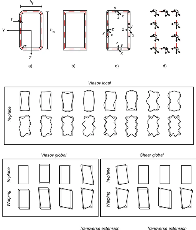
Figure 1a shows the RHS geometric parameters adopted in this work. The cross-section corners may be rounded, as shown in Figure 1b. For simplicity, the following illustrations are based on the straight-edge model (the procedure is identical for either case). The cross-section global axes are Y and Z, defining the major and minor bending axes, respectively. The cross-section is discretized by subdividing each cross-cross-section element (web, flange or corner) in straight walls of equal length. Figure 1c shows an example with two intermediate nodes in each web and one intermediate node in each flange. Mid-surface local axes (x, y, z) are set up in each wall, along which the corresponding displacements pertaining to each mode k are defined (𝑢𝑘, 𝑣𝑘, 𝑤𝑘 respectively). These displacement components are expressed as
uk=u̅k(y)𝜙k,x(x),
vk= v̅k(y)𝜙k(x), (4)
wk=w̅k(y)𝜙k(x),
where subscript commas indicate differentiation,u̅k(y), v̅k(y), w̅k(y) are the deformation mode shape functions and 𝜙k(x) are the corresponding amplitude functions.
An initial deformation mode basis is generated by considering three displacements along the local axes and one cross-section in-plane rotation per node, as shown in Figure 1d. This leads to a deformation mode space with 4N modes, where N is the total number of nodes. Note that this procedure is somewhat different from the classic GBT one, where the in-plane rotations are statically condensed. The displacement functions u̅k and v̅k are approximated by means of Lagrange linear polynomials, whereas Hermite cubic functions are employed for w̅k.
The final deformation modes are calculated as explained in [12,13,14], although the in-plane nodal rotations are included in the present case. This process is based on solving a set of eigenvalue problems, involving pairs of GBT modal linear and geometric stiffness matrices (see Eqs. (5) and (7) below), where the deformation modes correspond to the calculated eigenvectors. The modes are shown in Figure 1e and can be subdivided into three distinct sets: (i) Vlasov modes, which have null membrane shear strains (Vlasov’s assumption) and null membrane transverse extensions: four global modes (axial extension, two bending modes and one distortional mode) and several local modes, depending on the wall discretization. If the corners are rounded, the local modes will no longer have null in-plane displacements at the wall junctions and, furthermore, they involve warping displacements, as described in [15];
(ii) Shear modes (non-null membrane shear strains): four global modes (torsion and the warping functions of the Vlasov bending/distortional modes) and several local warping modes (depending on the wall discretization);
Figure 1: a) Geometry of rounded RHS, b) equivalent straight-edge RHS, c) discretization of the equivalent straight-edge RHS, d) initial DOFs and e) Deformation mode space.
In general, the local buckling of RHS members can be accurately predicted by the Vlasov local modes, but other modes may participate in the solution. For this reason, two variants of the GBT formulation were employed in the present work: (1) only Vlasov local modes and (2) all modes (totalling 4N modes). Variant 2 is the most accurate and simultaneously the most expensive from a computational point of view (particularly for refined cross-section discretizations), but makes it possible to assess the error associated with considering only the Vlasov local-plate modes.
For Variant 1, in which only the Vlasov local modes are employed, a rather fast procedure can be devised using the GBT modal linear stiffness matrices, which read (e.g., [12])
Bij=BijM+BijB=∫S1Etν2v̅i,yv̅j,y dy+∫ Et3
12(1ν2)w̅i,yyw̅j,yy dy
S ,
Cij=CijM+CijB= ∫S1αEtν2u̅iu̅j dy+ ∫ Et3
12(1ν2)w̅iw̅j dy
S , (5)
D1ij=D1Mij+DB1ij=∫SGt(u̅i,y+v̅i)(u̅j,y+v̅j)dy+∫ Gt 3
3 w̅i,yw̅j,ydy
S ,
where the M and B superscripts designate membrane and bending terms, respectively, G is the shear modulus and = 1 if the deformation modes include wall transverse extensions and = (1ν2) otherwise.
The Vlasov local modes are calculated using the following fast procedure:
1. The shear and transverse extension modes are removed by calculating the 2N dimension basis of the nullspace of (D1M+BM), which corresponds to the Vlasov modes (null membrane shear strains and null membrane transverse extensions).
2. The local modes are the λ ≠ 0 eigenvectors of BBv = λCv, except for the first one, which corresponds to distortion (the lowest non-null eigenvalue).
Sinusoidal amplitude functions of the form 𝜙k(x)= 𝜙̅ksin(πx L⁄ ), where L is the half-wavelength and 𝜙̅k is the mode amplitude, constitute the exact solutions for simply supported members and lead to the bifurcation equation [12]
(πL22 C + D +L 2
π2B + λ (X1+ π2
L2X2)) 𝝓̅=0, (6)
where λ is the load parameter, and D, X1 and X2 are linear and geometric stiffness matrices, which read
D = D1−D2−D2T, D2ij=D2Mij+D2Bij= ∫S1νEtν2v̅i,yu̅j dy+∫
νEt3
12(1ν2)w̅i,yyw̅j dy
S , (7)
X1ij= ∫Sσ(v̅i̅vj+w̅iw̅j) dy,
X2ij= ∫Sσ(u̅iu̅j) dy,
where σ is the longitudinal normal stress along the cross-section mid-line. The buckling eigenvalue problem (6) is computationally very efficient, since the number of DOFs equals the number of deformation modes included in the analysis. However, the calculation of the half-wavelength that corresponds to the minimum critical bifurcation load parameter requires an iterative strategy. In this work, the golden-section search algorithm was employed [16].
3. PARAMETRIC STUDY FOR STRAIGHT-EDGE RHS
3.1 Introduction
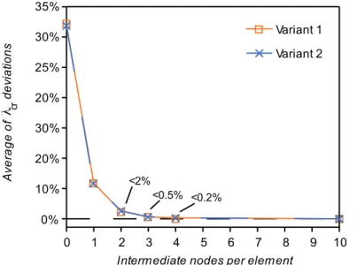
A total of 124 RHS cross-sections were analysed, with hw/bf values between 1 and 4, with a step of 0.1, and bf/t values ranging from 10 to 40, with a step of 10, which is in agreement with most standard commercial cross-sections. The cross-sections were modelled as straight-edge (as shown in Figure 1b) and simplified to their centreline. Fig. 2 shows a convergence analysis, indicating that for axial compression and uniaxial bending, a subdivision of each wall into 5 segments (four intermediate nodes) leads to results within 0.2% of those obtained with 10 intermediate nodes.
Figure 2: Maximum absolute deviation of the critical buckling stress for all cross-sections, under N,
My or Mz, with respect to those obtained with ten intermediate nodes per wall
The two variants presented in Section 2 are considered (analyses with the Vlasov local modes only or with all modes). Finally, several load combinations are addressed:
o simple individual loadings, namely axial force (N), major axis bending (Mz) or minor axis bending (Mz);
o combined loadings, namely N+My, N+Mz, My+Mz and N+My+Mz.
Table 1 shows a statistical summary of the differences in the results obtained with the two variants concerning several loading combinations involving axial force and biaxial bending. It is possible to observe a reduction of the critical buckling stress (which is proportional to the buckling coefficients) when all modes are considered, which strongly correlates with the bf/t ratio. Although not shown, both variants were validated through comparisons with results obtained with GBTUL [2] and CUFSM [3]. Noteworthy differences are obtained for bf/t =10 only, which corresponds to rather stocky cross-sections, where behaviour is not governed by local buckling phenomena1. For higher bf/t ratios, the accuracy is on average below 1%, with a small standard deviation. It is therefore acceptable to consider only the Vlasov local modes in the calculations. This approximation is very relevant, as it makes the buckling coefficients independent of the bf/t ratio. For this reason, the following analyses are carried out with Variant
1For example, according to [20], the minimum width-to-thickness ratio for which an internal compression part is unable to
develop its full plastic capacity equals 38√235/𝑓𝑦, where 𝑓𝑦 is the yield stress in MPa. This limit is well above 10 even for high strength steel grades.
1, making the buckling coefficients dependent only on (i) the stress distribution and (ii) the
hw/bf ratio.
Table 1: Reduction in critical buckling coefficients considering Variant 2 instead of Variant 1. 𝒃𝒇
𝒕 = 𝟏𝟎 𝒃𝒇
𝒕 = 𝟐𝟎 𝒃𝒇
𝒕 = 𝟑𝟎 𝒃𝒇
𝒕 = 𝟒𝟎
Min -11.1% -2.5% -1.1% -0.6%
Max -0.1% -0.0% -0.1% -0.0%
Average -2.9% -0.7% -0.3% -0.2%
Std. Dev 1.4% 0.3% 0.2% 0.1%
In Section 3.2 the influence of hw/bf for simple loadings (axial compression, major or minor axis bending) is investigated, in which case the results can be compared with those available in literature. In Section 3.3, combined loading cases are analysed, namely (i) axial compression with uniaxial bending, (ii) biaxial bending and (iii) axial force with biaxial bending. Finally, in Section 3.4, charts and analytical expressions to determine the local buckling coefficient are proposed. For readability purposes, the results concerning complex loading cases are presented for hw/bf= 1, 2, 3 and 4 only, as more detailed results can be found in [8].
3.2. Local buckling under simple loading cases
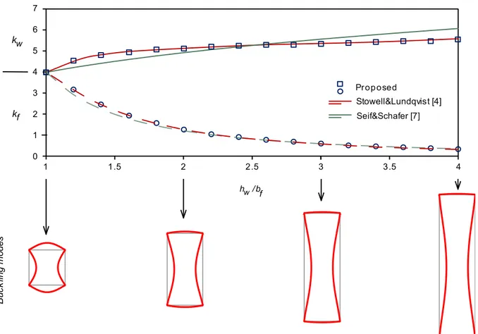
The graphs in Figures 3, 4 and 5 show the variation of both web and flange buckling coefficients with hw/bf, for axial compression, major and minor axis bending, respectively. In these figures, various buckling modes are also provided, scaled such that the web maximum displacement is constant.
For axial compression (Figure 3), the results coincide with those in [4], and differ slightly from those obtained with the analytical expressions provided in [7].. For major and minor axis bending, the proposed procedure and [7] provide similar buckling coefficients (see Figures 4 and 5).
The influence of hw/bf on kw and kf is noticeably dependent on the stress distribution. In the case of an axially compressed square tube, all walls are subject to uniform stresses and necessarily one has kw = kf = 4.0 (the result for simply supported square plates). By increasing
hw/bf, web buckling becomes increasingly restrained by the flange, resulting in an increase in
kw. At the same time, from Eq. (3), kf necessarily decreases.
Figure 3: Buckling coefficients and modes for axial compression.
Figure 4: Buckling coefficients and modes for major axis bending.
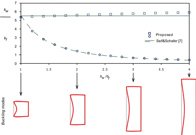
Figure 5: Buckling coefficients and modes for minor axis bending.
Overall, it is observed that, as hw/bf increases, buckling tends to be governed by the webs and not the flanges. For a given stress distribution, an increase in this ratio causes an increase in the relation between the web and flange compressed widths. At the same time, the flanges offer more restraint to the rotation of the corners. In fact, by analysing cross-sections with much higher hw/bf values, it can be observed that kw tends asymptotically to the value for built-in plates (6.97 for a fully compressed web and 39.6 for a web under bending [18]). The flange buckling coefficients, on the other hand, obviously tend to zero (see Figure 6).
Figure 6: Variation of kw/kf with hw/bf for a RHS under N, My or Mz.
3.3 Local buckling under combined loading
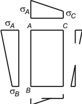
For combined loading the stress distribution may be parametrized using the arbitrary cross-section distribution shown in Figure 7 and
𝜓w=σσBA, 𝜓𝑓=σσCA, (8)
where 𝜓w, 𝜓fϵ[-1,1] and point A corresponds to the web-flange midline corner where the higher compressive stress occurs (in the present work, the webs always refer to the wider cross-section walls).
Figure 7: Normal stress distribution in a RHS under combined axial force and biaxial bending.
To enable a better understanding on how the stress profile relates to the critical local buckling, from here onwards reference is made only to kw, since instability is generally driven by web buckling. However, recall that kf may be easily retrieved from Eq.(3).
3.3.1 Axial compression and uniaxial bending
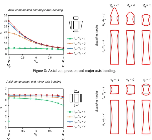
For axial compression and major axis bending 𝜓w varies and 𝜓f = 1, whereas for axial compression and minor axis bending the opposite occurs. The variation of kw with 𝜓w and 𝜓f, for selected values of hw⁄bf, and the most relevant buckling modes are displayed in Figures 8 and 9. It is observed that for narrower cross-sections (increasing values of hw⁄bf), the differences between the various curves become smaller. The same was observed already for axial compression and uniaxial bending, which constitute “boundary cases” and for which it was shown that, as hw/bf increases, the kw curves tend to a horizontal line. It should be noted that the minimum and maximum kw values are obtained for axial compression and uniaxial bending, respectively. The increase in the lower value of the linear stress diagram (which corresponds to moving from My or Mz to N) is necessarily associated with a lower buckling load, since there is a global increase in compressive stresses which makes the cross-section more susceptible to buckling. This can be attested by observing Figures 8 and 9 (the maximum web displacement of the buckling modes is kept constant): the critical local buckling coefficients decrease as one approaches axial compression.
Figure 8: Axial compression and major axis bending.
Figure 9: Axial compression and minor axis bending.
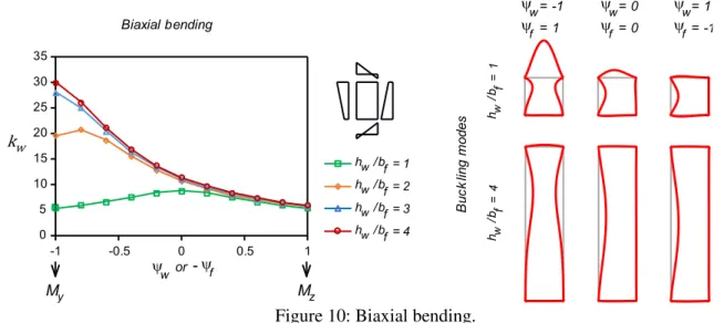
3.3.2 Biaxial bending
For biaxial bending both 𝜓w and 𝜓f may vary, but one has 𝜓w = −𝜓f. The variation of kw with hw⁄bf and the most relevant buckling modes are displayed in Figure 10. It is observed that as one moves from major to minor axis bending (i.e., 𝜓w moves from -1 to 1), the kw values for different hw/bf converge to approximately 5. It is also worth noting that the minimum kw value is always obtained for minor axis bending (𝜓f= 1 or, for a square tube, also 𝜓f= 1). Conversely, as hw⁄bf increases, the maximum kw is obtained for increasing 𝜓f values. In particular, this maximum value is attained for 𝜓f = 0, for a SHS, and for 𝜓f = 1 if hw⁄bf ≥ 3. The variation of the buckling modes follows a similar trend to that described regarding axial compression and uniaxial bending.
Figure 10: Biaxial bending.
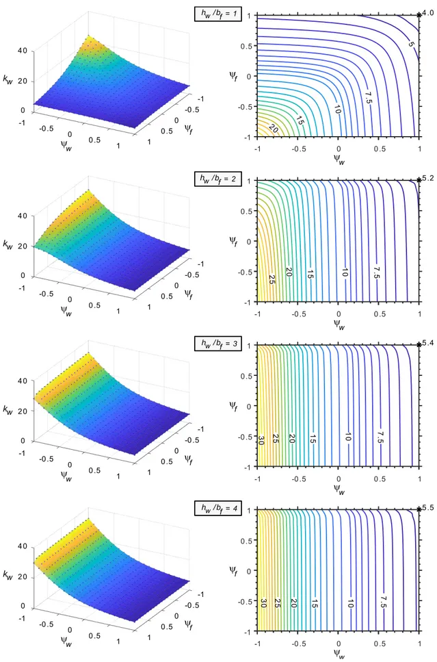
3.3.3 Combined axial force and biaxial bending
Combined axial force and biaxial bending constitutes the most general loading case. Figure 12 shows the web buckling coefficients obtained for different hw⁄bf values, displayed as (𝜓w, 𝜓f) surface plots and corresponding contour lines. To enable a better grasp of the following results and those presented earlier, Figure 11 identifies, in this 2D space, the “boundary cases” addressed so far. Note that 𝜓w< −𝜓f indicates that N > 0.
Figure 11: Identification of the load combinations in the (𝜓w, 𝜓f) 2D space.
Both the surface and contour plots were obtained from curve-fitting of the web buckling coefficients obtained for (𝜓w, 𝜓f) pairs defining a mesh with intervals of 0.1 along both directions. The MATLAB griddata method was used, which employs biharmonic spline interpolation.
It is observed that the buckling coefficient increases as 𝜓w and/or 𝜓f decreases, in agreement with the previous findings. For SHS, the surfaces are naturally symmetric with respect to the 𝜓w = 𝜓f axis and, for increasingly narrower RHS, they become mostly dependant on 𝜓w. This transition agrees with the gradual shift of the maximum kw for biaxial bending towards lower 𝜓w (see also Figure 10). Also note that, even for the highest cross-section ratio considered, kw decreases as 𝜓f approaches 1.
Figure 12: kw curve-fitted surface plots and contour lines for axial force and biaxial bending
3.4 Approximate formulae
With the results obtained in the previous sections, approximate expressions were developed for combined axial force and biaxial bending. The weighted linear least squares method was used, employing increasingly higher-order polynomials until correlation was deemed satisfactory. Instead of using 𝜓w and 𝜓f directly as input parameters, shifted coordinates 𝜓𝑤′ = 𝜓w− 1 and 𝜓𝑓′ = 𝜓f− 1 were adopted, since this simplifies considerably the resulting polynomials. Table 2 displays the proposed formulae for kw and Table 3 provides the relevant coefficients as a function of the hw⁄bf ratio. Note that the main and the cross-order coefficients are of the 4th and 5th degree, respectively, and that p00 = kw for axial compression. Finally, Table 4 provides a summary of the statistical regression information, showing that accurate results are obtained for the parameter ranges considered.
Table 2: kw formulae for different load cases. 𝑘𝑤
N-My-Mz p00+∑ (pi0(𝜓w−1)i+p0i(𝜓f−1) i
)
4
i=1
+∑ ∑pij(𝜓w−1)i(𝜓f−1)j
5-i
j=1 4
i=1
N p00
N-My p00+∑pi0(𝜓w−1)i
4
i=1
N-Mz p00+∑p0i(𝜓f−1)i
4
i=1
Table 3: Polynomial coefficients for the definition of kw.
hw⁄bf p00 p01 p02 p03 p04 p10 p20 p30 p40
1 4.000 -2.230 -1.585 -0.543 -0.070 -2.230 -1.585 -0.543 -0.070 2 5.158 -1.571 -2.396 -1.497 -0.322 -4.488 -6.436 -9.368 -2.727 3 5.384 -1.554 -2.432 -1.528 -0.329 -3.895 -3.141 -5.076 -0.822 4 5.541 -1.549 -2.445 -1.540 -0.333 -3.853 -2.577 -4.414 -0.518
hw⁄bf p11 p21 p12 p31 p22 p13 p41 p32 p23 p14
1 -1.373 -2.837 -2.837 0.018 -3.005 0.018 0.561 -0.945 -0.945 0.561 2 0.101 -2.660 1.592 -2.906 0.681 0.607 -1.489 0.473 0.141 0.021 3 1.574 -0.847 3.887 -0.081 -1.112 3.343 -0.285 0.323 -0.553 0.928 4 1.575 -0.665 3.816 0.219 -1.127 3.261 -0.081 0.183 -0.463 0.884
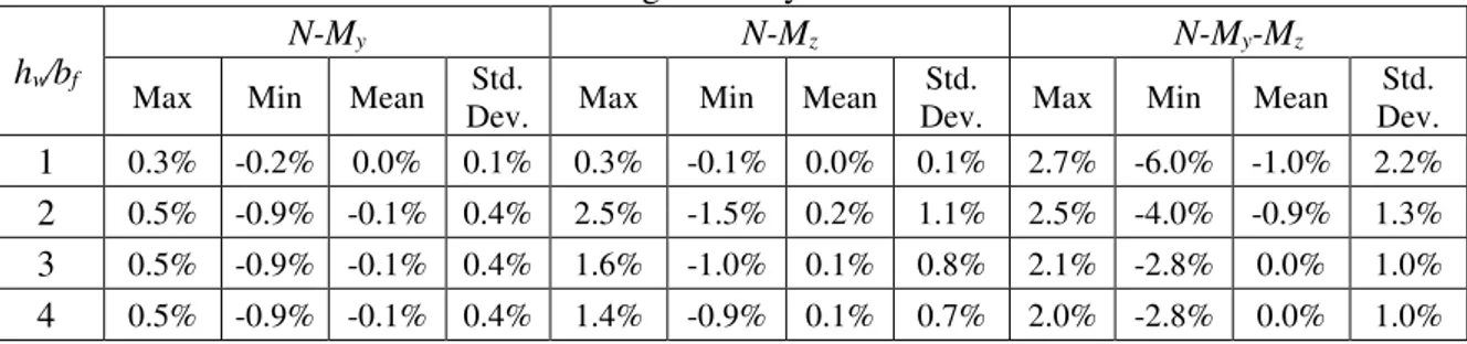
Table 4: Statistical information concerning the analytical formulas relative to the numerical model
hw⁄bf
N-My N-Mz N-My-Mz
Max Min Mean Std.
Dev. Max Min Mean Std.
Dev. Max Min Mean Std. Dev.
1 0.3% -0.2% 0.0% 0.1% 0.3% -0.1% 0.0% 0.1% 2.7% -6.0% -1.0% 2.2%
2 0.5% -0.9% -0.1% 0.4% 2.5% -1.5% 0.2% 1.1% 2.5% -4.0% -0.9% 1.3%
3 0.5% -0.9% -0.1% 0.4% 1.6% -1.0% 0.1% 0.8% 2.1% -2.8% 0.0% 1.0%
4. THE EFFECT OF ROUNDED CORNERS
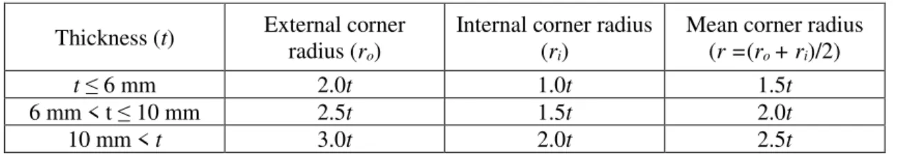
This section presents a preliminary study concerning the effect of rounded corners on the critical buckling coefficients of RHS under axial force, major axis bending or minor axis bending. The cross-section database of EN10219-Part 2 [19] is employed. The mean radii are computed in accordance with these specifications, reproduced in Table 5. According to these rules, some of the cross-sections are very compact, with very narrow flat parts, and can hardly be considered thin-walled. Out of the entire set of cross-sections, the cases in which the flat wall width is lower than 10 times the thickness were discarded, leading to a total of 188 cross-sections to analyse.
Table 5: Rules for determination of the mean corner radii
Thickness (t) External corner radius (ro)
Internal corner radius (ri)
Mean corner radius (r =(ro + ri)/2)
t ≤ 6 mm 2.0t 1.0t 1.5t
6 mm < t ≤ 10 mm 2.5t 1.5t 2.0t
10 mm < t 3.0t 2.0t 2.5t
4.1 Definition of the buckling coefficients in RHS with rounded corners
For RHS with rounded corners, the highest stress may be found at the corner, rendering the calculations somewhat complex. To avoid this case, new coefficients 𝑘̅̅̅̅𝑤 and 𝑘̅̅̅𝑓 are introduced, which relate to a fictitious stress 𝜎̅̅̅̅𝑐𝑟, found by “extending” the stress distribution to the intersection of the most compressed web and flange mid-lines, as shown in Figure 13:
𝜎̅̅̅̅ 𝑐𝑟= 𝑘̅̅̅̅𝑤 π
2E
12(1ν2)( t hw)
2
=𝑘̅̅̅𝑓 π
2E
12(1ν2)( t bf)
2
. (9)
Figure 13: Calculation of the fictitious stress 𝜎̅̅̅̅𝑐𝑟.
Naturally, the previous results for 𝑘𝑤and 𝑘𝑓 pertaining to straight edges are no more than a particular case of 𝑘̅̅̅̅𝑤 and 𝑘̅̅̅𝑓 when the radius is null.
The effect of the rounded corners may be assessed by means of the coefficient 𝑅𝑘, reading
𝑅𝑘 =𝑘𝑤,𝑠𝑡𝑟−𝑒𝑑𝑔𝑒𝑘̅̅̅̅𝑤 = 𝑘𝑓
̅̅̅̅
𝑘𝑓,𝑠𝑡𝑟−𝑒𝑑𝑔𝑒, (10)
where the subscript “str-edge” corresponds to a cross-section with the same geometry but with straight edges. With this coefficient it is possible to relate the critical load parameter of the two sections through
𝜆̅̅̅̅ = 𝑅𝑐𝑟 𝑘𝜆𝑐𝑟,𝑠𝑡𝑟−𝑒𝑑𝑔𝑒. (11)
4.2 Local buckling under simple loading cases
As in Section 3, analyses were first carried out using Variants 1 (only Vlasov local modes) and 2 (all modes), to assess the relevance of the non-Vlasov local modes. Figures 14, 15 and 16 show the 𝑘̅̅̅̅𝑤 results for axial compression, major axis bending and minor axis bending and the corresponding 𝑅𝑘values for the two Variants, as well as the web buckling coefficients for straight-edge RHS determined with Variant 2.
Figure 14: 𝑘̅̅̅̅𝑤 and 𝑅𝑘 for rounded-edge RHS under axial compression.
Figure 15: 𝑘̅̅̅̅𝑤 and 𝑅𝑘 for rounded-edge RHS under major axis bending.
Figure 16: 𝑘̅̅̅̅𝑤 and 𝑅𝑘 for rounded-edge RHS under minor axis bending.
From these three load cases, two conclusions can be withdrawn:
(i) With rounded corners, the buckling coefficient 𝑘̅̅̅̅𝑤 increases for almost every case and for both variants (thus implying that 𝑅𝑘 > 1), namely for SHS. This is due to a stiffening effect caused by the reduction of the flat portions of the webs/flanges and also the fact that the buckling mode involves significant membrane warping, as shown in Figure 17 (this warping vanishes for straight edges).
(ii) The non-Vlasov local modes play an important role in the local buckling behaviour for RHS with rounded corners, since their inclusion in the analyses leads to lower values of 𝑘𝑤
̅̅̅̅ (and 𝑅𝑘). This shows that the local buckling behaviour of RHS with rounded corners is much more complex than that for RHS with straight edges (note in Figure 17 that the local buckling modes no longer have null in-plane displacements of the wall junctions).
Figure 17: Buckling modes for a rounded-edge SHS under axial compression and uniaxial bending.
Lastly, the influence of the mid-line corner radius is investigated considering the results obtained with Variant 2. The graphs in Figure 18 plot 𝑅𝑘, for the selected values of the radius-to-thickness ratio, as a function of the parameter (hw+bf)/r, which takes lower values as the corner radius increases with respect to the equivalent straight-edge cross-section mid-line dimensions. The results show that there is a tendency for 𝑅𝑘 to increase as the relative size of the corners increases, particularly for the cases of major and minor axis bending, in which case a trend is most evident and 𝑅𝑘 reaches higher values. Although there is still a slight scatter, it can be reduced by subdividing the results in each graph according to the corresponding r/t ratio, which shows that this parameter is also relevant.
Figure 18: Influence of the corner radius to the coefficient 𝑹𝒌
5 CONCLUSION
This paper assessed the local buckling behaviour of thin-walled RHS members subjected to combinations of axial load, major and minor axis bending. The minimum critical local buckling loads were calculated by means of a computationally efficient GBT specialization for RHS.
For straight edges, the results showed that the inclusion of the Vlasov local deformation modes in the buckling analysis is sufficient to provide accurate bifurcation loads for non-compact cross-sections. This simplification made it possible to perform analyses considering only (i) the cross-section normal stress distribution and (ii) the mid-line height-to-width ratio (hw⁄bf). The results obtained with the proposed model agree very well with those available in literature for either axial compression, major or minor axis bending. The cases of combined (i)
axial compression and uniaxial bending, (ii) biaxial bending and (iii) combined axial force and biaxial bending, were handled for the first time. For each case, charts and approximate analytical expressions obtained through curve-fitting techniques were presented.
For rounded corners, it was shown that the buckling modes are significantly more complex and that an accurate calculation of the critical buckling load requires including all sets of GBT cross-section deformation modes in the analysis. Moreover, it was demonstrated that, with respect to the straight edge case, the buckling loads increase due to a stiffening of the cross-section resulting from the reduction of the flat portion of the cross-cross-section and the occurrence of significant membrane warping.
Further studies are currently under way to investigate the effect of rounded corners for RHS subjected to arbitrary loading.
ACKNOWLEDGEMENTS
The authors of this paper gratefully acknowledge the financial support provided by the Research Fund for Coal and Steel project RFCS-2015-709892, “Overall-Slenderness Based Direct Design for Strength and Stability of Innovative Hollow Sections –HOLLOSSTAB”.
REFERENCES
[1] CEN, EN 1993-1-5. Eurocode 3 : Design of Steel Structures - Part 1-5: Plated structural elements. 2006.
[2] R. Bebiano, D. Camotim, and R. Gonçalves, “GBTUl 2.0 − A second-generation code for the
GBT-based buckling and vibration analysis of thin-walled members”, Thin-Walled Struct., 124, 235–257, 2018.
[3] Z. Li and B. W. Schafer, “Buckling analysis of cold-formed steel members with general
boundary conditions using CUFSM: Conventional and constrained finite strip methods”,
Proceedings of the Twentieth International Specialty Conference on Cold-Formed Steel Structures, 17-31, 2010.
[4] E. Z. Stowell and E. E. Lundquist, “Local Instability of Columns with I-, Z-, Channel, and
Rectangular-Tube Sections”, Natl. Advis. Comm. Aeronaut. Washington, D.C, U.S.A., 1939. [5] F. Bleich, Buckling strength of metal structures, McGraw-Hill, New York, 1952.
[6] H. G. Allen and P. S. Bulson, Background to buckling, McGraw-Hill, London, 1980.
[7] M. Seif and B. W. Schafer, “Local buckling of structural steel shapes”, J. Constr. Steel Res.,
66(10), 1232–1247, 2010.
[8] L. Vieira, R. Gonçalves, and D. Camotim, “On the local buckling of RHS members under axial force and biaxial bending”, Thin-Walled Structures, 129, 10–19, 2018.
[9] R. Schardt, Verallgemeinerte Technische Biegetheorie, Springer-Verlag, Berlin, 1989.
[10] D. Camotim, N. Silvestre, R. Gonçalves, and P. B. Dinis, “GBT-based Structural Analysis of Thin-walled members: Overview, Recent Progress and Future Developments”, Adv. Eng. Struct. Mech. Constr., 140, 187–204, 2006.
[11] D. Camotim, C. Basaglia, R. Bebiano, R. Gonçalves, and N. Silvestre, “Latest developments in the GBT analysis of thin-walled steel structures”, Proceedings of the International Colloquium on Stability and Ductility of Steel Structures, 2010.
[12] R. Gonçalves, M. Ritto-Corrêa, and D. Camotim, “A new approach to the calculation of
cross-section deformation modes in the framework of generalized beam theory”, Comput. Mech.,
[13] R. Gonçalves, R. Bebiano, and D. Camotim, “On the Shear Deformation Modes in the Framework of Generalised Beam Theory”, Thin-Walled Structures, 84, 325–334, 2014.
[14] R. Bebiano, R. Gonçalves, and D. Camotim, “A cross-section analysis procedure to rationalise and automate the performance of GBT-based structural analyses”, Thin-Walled Structures, 92, 29–47, 2015.
[15] R. Gonçalves and D. Camotim, “GBT deformation modes for curved thin-walled cross-sections based on a mid-line polygonal approximation”, Thin-Walled Structures, 103, 231–243, 2016. [16] J. Kiefer, “Sequential Minimax Search for a Maximum”, Proc. Am. Math. Soc., 4(3), 502, 1953. [17] The MathWorks Inc., “MATLAB.” Natick, Massachussets, 2017.
[18] T.V. Galambos, Guide to Stability Design Criteria for Metal Structures, T.V. Galambos (ed.), New York, John Wiley & Sons, Inc., 1988.
[19] CEN, EN 10219-2 Cold formed welded structural hollow sections of non-alloy and fine grain steels - Part 2: Tolerances, dimensions and sectional properties. 2006.