Proceedings of the Annual Stability Conference Structural Stability Research Council Orlando, Florida, April 12-15, 2016
Recent Developments in the GBT-Based Numerical Modeling of
Steel-Concrete Composite Beams
Rodrigo Gonçalves1, David Henriques, Dinar Camotim2
Abstract
This paper presents the latest developments concerning the numerical modeling of steel-concrete composite beams using GBT-based (beam) finite elements. In particular, it is shown that GBT makes it possible to assess, accurately and with computational efficiency, the buckling (bifurcation) behavior of steel-concrete composite beams subjected to negative (hogging) bending. Two relevant buckling phenomena are considered, namely (i) local buckling of the web (plate-like), possibly involving the torsional rotation of the compression flange, and (ii) distortional buckling, combining a lateral displacement/rotation of the lower flange with cross-section transverse bending. The determination of the buckling loads is performed in two stages: (i) a pre-buckling analysis is first carried out, accounting for shear lag and concrete cracking effects, and (ii) an eigenvalue buckling analysis is performed next, on the basis of the calculated pre-buckling stresses, allowing for cross-section distortion and plate bending. Several numerical examples are presented, illustrating the application of the proposed GBT-based finite element and providing clear evidence of its capabilities and potential.
1. Introduction
The design of continuous steel-concrete composite beams requires the performance of stability checks in negative (hogging) moment regions. The relevant buckling phenomena are usually termed (see Fig. 1(a)):
(i) “local”, combining plate-like web bending and bottom (compressed) flange rotation, and (ii) “ lateral-distortional” (or simply “distortional”), where the bottom flange undergoes a lateral displacement and the cross-section (mainly the web) experiences transverse bending. In addition, the beam failure mode may also be influenced by web shear buckling. In Eurocode 4 (EC4 CEN 2004), (i) local buckling is taken into account through the use of an effective width approach, (ii) shear buckling is covered by means of specific checks and (iii) the design buckling resistance to distortional buckling is calculated using stability curves and requires the calculation of elastic critical buckling loads, resorting to the so-called “continuous inverted U-frame” model (e.g., Johnson & Anderson 2004 see Fig. 1(b)), which is not a trivial task. The calculation of elastic distortional buckling loads has deserved the attention of several researchers in the past. For instance, it is worth mentioning here (i) the beam finite element approach of Bradford & Trahair (1987) (see also, e.g., Bradford & Gao 1992), which accounts for web cubic deformation and independent rotations of the flanges, (ii) beam on elastic foundation-type solutions (Svensson 1985, Hanswille et al. 1998, Hanswille 2002) and (iii) other spring-type models (Dekker et al. 1995).
1
CERIS, ICIST and Universidade Nova de Lisboa, Portugal, <[email protected]> 2
Figure 1: Steel-concrete composite beams: (a) distortional and local buckling modes and (b) inverted U-frame. Generalized Beam Theory (GBT) is a thin-walled prismatic bar theory that efficiently handles cross-section in-plane and out-of-plane (warping) deformation, through the inclusion of “cross-section deformation modes”. GBT was originally proposed by Schardt (1966, 1989), has since been considerably developed (particularly in the last decade) and is currently well established as a very efficient and valuable numerical tool to analyze the linear, buckling, post-buckling, vibration and dynamic behavior of thin-walled members (e.g., Camotim et al. 2010a, 2010b).
GBT was first applied in the field of steel-concrete composite beams/bridges by Gonçalves & Camotim (2010), who demonstrated that GBT can handle, with particular efficiency, complex effects such as cross-section distortion, the presence of transverse diaphragms, shear lag or shear connection flexibility. Several illustrative examples were presented, concerning linear elastostatic and undamped free vibration analyses, and semi-analytical solutions were provided for simply supported members under uniform negative moment. Concrete cracking and other types of material non-linearity were not taken into consideration. Very recently, Henriques et al. (2015) developed a very accurate and computationally efficient physically non-linear GBT-based beam finite element, able to capture the materially non-linear behavior of wide-flange steel and steel-concrete composite beams up to collapse. This finite element incorporates the effects of concrete cracking/crushing, shear lag in wide flanges and steel plasticity. It was shown that the proposed beam finite element can offer significant advantages, with respect to standard shell/solid finite element and finite strip models, since (i) it becomes possible to obtain semi-analytical solutions (albeit for particular cases), (ii) a much smaller DOF number is generally required to achieve accurate results, even in full numerical analyses, (iii) the computation times are greatly reduced, particularly in physically non-linear problems, and (iv) the GBT modal decomposition of the solution into hierarchic and structurally meaningful cross-section deformation modes provides invaluable insight into the mechanics of the problems being analyzed.
This paper focuses on local and distortional buckling (bifurcation) of steel-concrete composite beams under variable bending moment. A computationally efficient GBT-based beam finite element is developed to calculate the buckling loads. The pre-buckling stresses are calculated accounting for shear lag and concrete cracking effects, and the buckling analysis is designed to comply with the EC4 “inverted U-frame model” requirements, even if it can be modified to accommodate other assumptions. In addition, web and/or compression flange local buckling is also accounted for since shear buckling is usually checked separately, no allowance for this phenomenon is made. To illustrate the application and capabilities of the proposed GBT-based finite element, numerical results are presented and discussed. For comparison and validation purposes, values obtained with finite strip analyses are provided.
2. GBT Formulation for the Buckling Analysis of Steel-Concrete Composite Beams
2.1 Fundamentals
2012), although the geometric nonlinear effects are simplified in accordance with the assumptions usually made in the context of linearized buckling analyses.
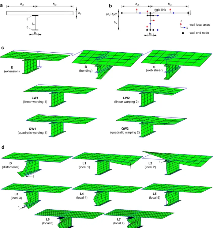
It is assumed that the beam cross-section is of the type shown in Fig. 2(a), i.e., combining a reinforced concrete slab with an I-section steel beam. Fig. 2(b) displays the wall mid-lines and local axes (x defines the beam longitudinal direction), which constitute the basis of the GBT kinematic description. Each reinforcement layer is deemed smeared along the appropriate direction (y for the longitudinal rebars and x
Figure 2: Steel-concrete composite beam (a) cross-section, (b) wall mid-lines and boundary conditions, (c) deformation modes for the pre-buckling analyses and (d) additional deformation modes for the buckling analyses (renderings
for the transverse rebars) and a perfect bond between rebars and concrete is assumed. The cross-section is subdivided into the following walls: (i) two flanges and one web, for the steel I-section, and (ii) two reinforced concrete flanges of widths bc1 and bc2. Throughout the paper, the parameters associated with the concrete slab, steel I-section beam and rebars are identified by the subscripts c, a and s, respectively. Using the wall mid-surface local axes and Kirchhoff's thin plate assumption, the GBT displacement field for each wall is given by vector U, of the form
, ) ( ) ( ) ( ) ( ) , , ( , x x y z y U U U z y x x U U z y x φ φ Ξ Ξ U (1) , ) ( , ) ( , 0 0 0 w w 0 Ξ 0 w 0 v u 0 Ξ T y T U T T TU y y (2)
where the commas indicate differentiations, (x) is a column vector containing k=1, ..., D deformation mode amplitude functions (D is the number of deformations modes included in the analysis) and
) ( ), ( ),
(y v y w y
u are column vectors containing the wall mid-line displacement functions, along
x, y, z, characterizing each deformation mode. The calculation of these displacement functions, for the particular case of steel-concrete beams, is explained next for general cross-sections they can be obtained from the so-called “GBT cross-section analysis for arbitrary sections”, described by Gonçalves et al. (2010, 2014) and Bebiano et al. (2015), and already implemented in the GBTUL program, freely available at www.civil.ist.utl.pt/gbt.
The Green-Lagrange strains E follow straightforwardly from the displacement field U. The non-null strain components are subdivided into membrane (M) and bending (B) parts, where the latter are always assumed to be small. A plane stress state is assumed and equilibrium is established in terms of E and second Piola-Kirchhoff stresses S, through the virtual work statement. A Voigt-like notation and the wall local axes are employed, with ET = [Exx Eyy 2Exy] and ST = [Sxx Syy Sxy].
2.2 Pre-Buckling Analysis
The pre-buckling analysis follows closely the methodology employed by Henriques et al. (2015), although concrete cracking is the only source of physical non-linearity considered here. It is assumed that the cross-section is in-plane undeformable and that Vlasov’s null membrane shear strain hypothesis holds in the steel beam flanges. Under these assumptions, the only cross-section deformation modes that it is necessary to include in the analyses are those displayed in Fig. 2(c): axial extension (E), Euler-Bernoulli bending (B) (calculated assuming that the concrete is uncracked), web shear (S) (in-plane displacements of the B mode, excluding warping, thus generating a uniform membrane strain distribution inthe web) and linear/quadratic warping (LW/QW) modes in each concrete wall, accounting for shear lag effects. Although additional modes can be included, it has been shown previously (Henriques et al. 2015) that the LW/QW modes are sufficient to obtain excellent results, even when steel plasticity and concrete crushingeffectsareaccountedfor.Itshouldstillbenoted that, even if no axial force is applied, the E mode must be included in the analysis, to capture the neutral axis shift due to cracking and shear lag effects. The only non-null stress components are M
xy M
xx B
xx S S
t t t G E 0 0 0 0 0 0 0
C , (3)
where Et and Gt are the tangent uniaxial and shear moduli, respectively.. For steel (I-section and rebars), a
linear elastic constitutive relation is adopted, although the rebars behave uniaxially (Gt=0). Note that
the transvers rebars are not taken into consideration in the pre-buckling analyses, as the deformation modes considered do not involve Eyy. Concerning the concrete material behavior, a simplified version of the constitutive law proposed by Henriques et al. (2015) is adopted, characterized by null tensile strength and a linear compressive branch. Since it is assumed that Syy=0, generalized cracking inevitably
develops if Sxy0. Separate laws are adopted for Sxx and Sxy, with the former directly related to the
longitudinal strains Exx through the specified uniaxial law. As for Sxy, a linear elastic relation is adopted,
with the elastic shear modulus affected by a reduction factor 1 to account for cracking (i.e., Gt=Gc).
A standard GBT finite element interpolation of the amplitude functions is employed,
= d (4)
where matrix contains the interpolation functions and vector d contains the unknowns (the amplitude function nodal values). Hermite cubic polynomials are employed for the B and S modes, whereas Lagrange quadratic polynomials are used for the E, LW and QW modes (those involving warping and null in-plane displacements). This interpolation leads to a 23 DOF element if all seven deformation modes are considered. In the case of symmetric sections, the shear lag modes may be paired (LW1+LW2 and QW1+QW2), thus leading to a 17 DOF element.
The out-of-balance force vector g, tangent stiffness matrix Kt and incremental load vector f are
obtained from the numerical integration of the expressions
, , , , , , , , , , ,
d dV d dV T U T x V xx x t T T xx x t T U T x V T T xx x q Ξ Ψ Ψ f Ψ Ψ Ψ Ξ C Ξ Ψ Ψ Ψ K q Ξ Ψ Ψ σ Ξ Ψ Ψ Ψg
(5)
where V is the member (beam) volume, Ξis a modal strain-displacement operator and qare forces acting along the walls mid-surface (for simplicity, volume forces are not considered in this work). Numerical integration is carried out using, in each wall, 3 Gauss points along x and 5 points along both y and z these numbers proved to be sufficient for the problems analyzed. The pre-buckling
analysis is carried out using Newton-Raphson iterations for a single load step, defining the reference loading for the subsequent buckling analysis (calculation of the bifurcation loads).
2.3 Buckling Analysis
Since the buckling problems addressed in this paper are essentially triggered by longitudinal normal stresses, only the non-linear term associated with longitudinal extension is retained. The buckling analysis is carried out by solving the standard eigenvalue problem associated with the linearized buckling analysis concept, on the basis of the calculated membrane pre-buckling stress M
xx
With respect to the pre-buckling analysis, additional cross-section deformation modes must be included to enable capturing local and distortional buckling. Although the M 0
yy M
yy S
E assumption is still retained, transverse bending and torsional stresses/strains inevitably develop, caused by the local and distortional deformations, and the tangent constitutive matrices must be changed accordingly. For steel, a linear constitutive law is considered, making it is possible to uncouple the membrane/bending terms and integrate in the trough-thickness direction, as in the case of the shell-like stress resultant concept employed by Gonçalves & Camotim (2011, 2012). For the steel beam, this leads to
. 2 1 0 0 0 1 0 1 ) 1 ( 12 , 0 0 0 0 0 0 0 2 3 a a a a a B a a a M a t E G E C C (6)
For the longitudinal rebars, only the membrane component is considered and integration along z provides
, 0 0 0 0 0 0 0 0 sx s M s A E C (7)
where Asx is the longitudinal rebar area per unit length. The transverse rebars are included in the
concrete slab, as explained next.
For concrete, the integration along z leads to
, 12 0 0 0 0 0 0 ) 1 ( 12 , 0 0 0 0 0 0 0 3 2 3 c c fcy c c tcx B c c c c tcx M c h G D h E h G h E C C (8)
where (i) Etcx is assumed constant along z (the value at z=0, obtained from the pre-buckling analysis,
is adopted), (ii) Gc is always affected by (recall that the concrete is always cracked in some
direction) and (iii) Dfcy is the transverse bending stiffness, which must include the contribution of the
transverse reinforcement3 and account for cracking, if required (as is the case of EC4).
The geometrically non-linear term is also integrated in the through-thickness direction, leading to
, , , ,
, , , x M xx T y y T y y T x xxxx S dz t S
E φ v v w w φ
(9)where denotes an incremental (buckling) variation. For the finite element solution, the interpolation scheme of the pre-buckling analysis is employed, although a larger number of deformation modes are included in the analysis. The discretized eigenvalue problem is cast in the standard form
3
Note that, since it is assumed that M 0
yy
(Kt + G)d = 0, (10)
where the linear and geometric stiffness matrices read
, , , , , , , , , , , ,
d tS d x T y y T y y T x M xx V xx x B B t T B M M t T M T xx x t Ψ w w v v Ψ G Ψ Ψ Ψ Ξ C Ξ Ξ C Ξ Ψ Ψ ΨK
(11)
and it should be noted that through-thickness integration is not required. Numerical integration is carried out with the same number of Gauss points, along x and y, as that adopted for the pre-buckling analyses. Concerning the cross-section deformation modes, those employed in the pre-buckling analysis must be complemented to enable capturing distortional and local buckling effects. The cross-section structural model employed for the calculation of these modes is shown in Fig. 2(b), where the sliding boundary condition at the far-right end node of the concrete slab corresponds to a symmetry simplification of the inverted U-frame model4. The following modes are considered (see Fig. 2(d)):
(i) A distortional mode D, calculated by imposing a unit lateral displacement (along y) in the lower flange and enforcing Vlasov’s assumption in all walls. This mode involves warping and cross-sectionin-planedeformationandcompletes the so-called “Vlasov natural mode set” (Gonçalves et al. 2010), which becomes completely defined by the E+B+D modes (for symmetric deformation). Note that this deformation mode involves transverse bending of the concrete (although it is generally minute), which is calculated taking into account the relevant boundary conditions in the concrete flange (in the present case, the sliding support).
(ii) A set of local modes that do not involve warping and capture localized deformation: (L1) a vertical displacement of the far-right concrete node, (L2) a rotation of the concrete node above the web , (L3) a rotation of the lower flange/web intersection and (L4-L7) local deformation in the web, corresponding to polynomials of increasing degree and null displacements and rotations at the web/flange junctions, with wk fk/max( fk) and
. 4 3 4 2 4 , 3 2 3 , 2 , 2 2 7 2 2 6 2 2 5 2 2 4 w w w w w w w w w w h y h y h y h y y f h y h y h y y f h y h y y f h y y f (12)These local modes are not typical of GBT-type analyses, as cross-section in-plane rotational DOFs are being considered. In particular, mode L1 only involves the right-hand side of the concrete slab and modes L4-L7 only involve the web recall that the classic GBT deformation modes are
4
mutually orthogonalized and, therefore, involve displacements throughout the whole cross-section. The present (“non-standard”) approach is followed to enable a clearer mechanical interpretation of the results, as each mode is associated with specific localized deformations.
It should be mentioned that it has been assumed that the lower flange is sufficiently stocky to preclude the occurrence of transverse bending in this wall. Although such effect can be easily incorporated, by including additional local deformation modes (in the lower flange), this has not been done in this work. For other cases, namely when the slab is continuous over several beams, the boundary conditions must be changed accordingly. Naturally, this can be easily handled with GBT. The inverted (single) U frame model was adopted here because it falls on the conservative side.
3. Numerical Examples
3.1 Linear Elastic Shear Lag
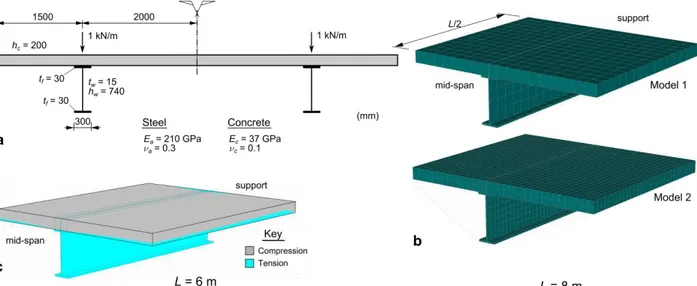
First, in order to illustrate the capabilities of the pre-buckling analysis, an elastic shear lag problem is presented (Henriques et al. 2015). The cross-section geometry and material parameters are shown in Fig. 3(a). Two simply supported spans of length L=6m and L=8m are considered and the loading consists of a 1kN/m uniformly distributed vertical loads acting in the web planes. Due to the double symmetry, only a “quarter” of the twin-beam (half of the length and cross-section) is analyzed.
Figure 3: Elastic shear lag: (a) cross-section geometry, loading and material parameters, (b) brick finite element models and (c) neutral surface obtained with the brick model 2.
The GBT analyses are carried out with 8 equal-length finite elements. Since the material behavior is assumed elastic, numerical integration is carried out with only 2/3 integration points along z/y, respectively, in each wall. For comparison purposes, analyses with 20-node brick finite elements were carried out using ATENA (Cervenka et al. 2013) and two refinement levels (see Fig. 3(b)), where
Figure 4: Elastic shear lag: (a) mid-span Sxx distributions at the concrete slab mid-height and (b) slab mid-surface contour
The stresses obtained with the GBT and brick element models are compared in Fig. 4. In particular, the top graphs plot the mid-surface Sxx distributions at mid-span and the bottom figures display surface
plots of both Sxx and Sxy (also mid-surface values). In spite of the huge difference in the DOF numbers
involved in each model, the GBT and brick element model stresses are generally in very good agreement, specially the mid-span values. The shear lag effects are quite visible and, naturally, more pronounced for the shorter span. Note also that the unequal concrete flange widths cause asymmetric stress distributions. Concerning the mid-span stresses (top graphs), the GBT distributions display a sharp peak over the web,
due to the “point” contact assumed between the concrete and the steel top flange. The brick element models predict a smoother stress distribution in this zone, due to the existence of a contact surface between the steel flange and concrete. Although hardly necessary, this contact zone can also be modeled in the GBT analyses, by employing a subdivision of the concrete walls into contact and no-contact wall segments. Note also that the effect of the contact zone is clearly visible in the Sxy surface plots, as the
GBT/brick results vary abruptly/smoothly from one side to the other. Finally, note that the GBT Sxy
surface plots yield non-null values at x=0. This effect can only be mitigated by including transverse extension modes in the analysis, rendering the GBT formulation unnecessarily more complex.
3.1 Buckling of Simply Supported Beams under Negative Bending
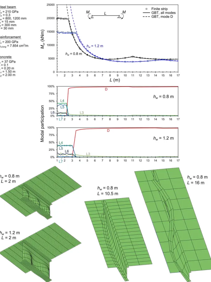
This illustrative example concerns simply supported beams subjected to uniform negative moment. The relevant geometrical and material parameters, as well as the results obtained, are given in Fig. 5. Two steel web height (hw) values are considered and the span L varies between 1 and 17m. The
longitudinal reinforcement is deemed located at z=0 and the concrete slab is assumed uncracked in the transverse direction (the contribution of the transverse reinforcement is not considered).
Due to the uniform bending, no shear lag effects exist in the pre-buckling analyses and the deck is fully cracked in the longitudinal direction. In this case, sinusoidal amplitude functions provide exact solutions and, therefore, the finite strip software CUFSM (Li & Schafer 2010) can be employed for comparison purposes. The GBT buckling analyses are carried out with 10 equal-length finite elements. The top graph of Fig. 5 displays the variation of the critical buckling moment with L and the two bottom diagrams provide the corresponding GBT modal participations, obtained by means of a strain energy criterion. Furthermore, a representative sample of the GBT buckling modes is also shown. It is observed that the GBT results are in excellent agreement with the finite strip ones throughout the whole
L range considered, which demonstrates that the GBT deformation modes selected are appropriate for the problem under consideration. These results make it possible to conclude that, as expected, local buckling is characterized by very small half-wave lengths, whereas distortional buckling is associated with moderate half-wavelengths and is the critical mode for spans of practical interest. The GBT modal participation diagrams show that the local buckling mode has major contributions from modes L4/L5 (web local deformation) and noteworthy participations of modes L3/L6 (rotation of the lower flange and web local deformation with 3 half-waves). On the other hand, the distortional mode essentially corresponds to the D mode, with a very small participation of mode L3 (note also that this deformation mode is the only one participating in both buckling modes). The dashed curves in the top graph correspond to buckling analyses performed with the D mode alone and clearly show that the results obtained are very accurate, practically matching those determined with all modes for the length range associated with critical distortional buckling. It is still worth mentioning that increasing the web height
hw influences significantly the local buckling load (as expected), but has a minute effect on the
3.2 Buckling of Two-Span Beams Subjected to Uniformly Distributed Loads
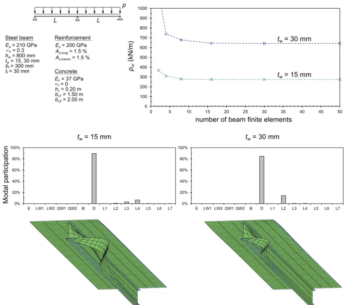
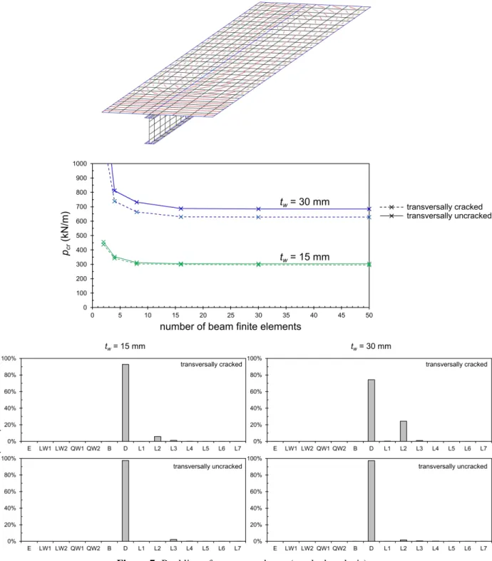
Consider the two-span composite beam shown in Fig. 6, subjected to a uniformly distributed load. All relevant material and geometric parameters are displayed in the figure note that two web thickness values are considered. The supports fully restrain all cross-section in-plane displacements, but completely allow cross-section warping. This problem is considerably more complex than the previous one, since the pre-buckling stresses vary quite rapidly along the beam span and, therefore, the buckling mode is localized in the negative bending region, near the intermediate support.
The GBT pre-buckling analysis is performed using a symmetry simplification, whereas the buckling analysis takes advantage of the anti-symmetry of the buckling modes with respect to the intermediate support. Such strategy makes it possible to analyze a single span and achieve a significant economy in terms of DOF number.
First, a fully uncracked analysis is carried out, where the contribution of the reinforcement is discarded. The results are shown in Fig. 6: (i) the top graph shows the the critical load as a function of the number
of finite elements, for the two web thickness values considered, (ii) the bottom graphs display the modal participations in each case (for discretizations involving 50 finite elements) and (iii) the corresponding buckling mode shapes are shown below. The top graph makes it possible to conclude that at least 10 GBT-based finite elements are necessary to achieve acceptable solutions. Note also that, naturally, the buckling load is higher for the stockier web. The buckling modes and the modal participations evidence a distortional-type behavior, although the deformation is quite localized near the intermediate support and has small participations from the local modes: (i) for tw=15mm, contributions from the bottom flange
and web local modes are observed (3% for L3 and 7% for L4), whereas (ii) for tw=30mm, a significant
contribution of the top flange rotation mode is obtained (14% for L2).
Next, the pre-buckling analyses are performed taking cracking into account. For illustrative purposes, the cracking pattern obtained is displayed in Fig. 7. For the buckling analyses, two Dfcy values are
considered, corresponding to transversally uncracked and cracked concrete the latter case is the one prescribed by EC4. The results are also displayed in Fig. 7, namely the buckling load as a function of the number of finite elements and the modal participations. A comparison between these buckling loads and those shown in Fig. 6 reveals that the former, with respect to the latter, (i) do not change significantly for the transversally cracked case and (ii) increase for the transversally uncracked case, particularly when
tw=30mm. This is explained by the fact that (i) the cracked pre-buckling analysis leads to more localized
compressive stresses (and, hence, higher buckling loads) and (ii) the transversally uncracked beam is associated with an increased U-frame stiffness (higher buckling loads), an effect that is more pronounced when the web is stockier (tw=30mm). The modal participation graphs, located in the bottom part of the
figure, show that the buckling mode of the transversally uncracked beam essentially coincides with the distortional deformation mode, whereas other deformation modes have relevant contributions for the transversally cracked beam.
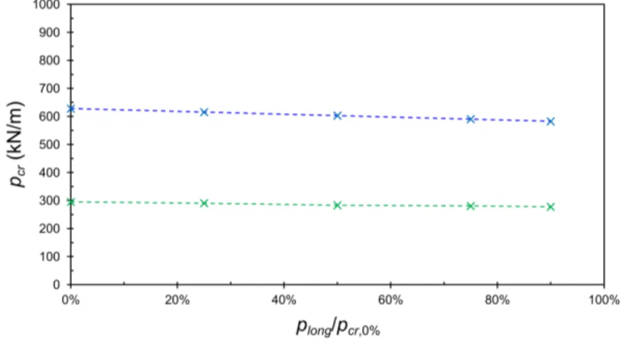
Finally, the influence of the long/short term loading ratio is analyzed. With the proposed finite element, this effect can be accounted for by performing separate pre-buckling analyses, in order to calculate the accumulated stresses in the beam. For instance, assuming that a short-term loading is superimposed on a long-term one, two separate pre-buckling analyses must be performed: (I) a long-term analysis, where creep effects are taken into account by means of an appropriate concrete modular ratio, and (II) a short-term analysis, whose load is incremented until the buckling load is reached. Then, the buckling eigenvalue problem reads
S
d j I IIt xxM j Tx y Ty y Ty x
j
II I
t
, ,
,
, , , , ,
,
Ψ
w w v v
Ψ
G
0 d G G
K
(13)
where it should be noted that the loading parameter only affects the short-term loading. Naturally, the sameprinciplecanbeappliedtoassesstheeffects of the evolution of the static system during construction. The graph in Fig. 8 shows the results obtained adopting a concrete modular ratio of 2 and increasing the ratio between the long-term loading and the buckling load obtained for short-term loading alone (pcr,0%).
In all cases, 50 finite elements were considered and cracking was allowed for in the longitudinal and transverse directions. These results show that the critical buckling load decreases slightly with the above ratio, with a maximum drop (at a ratio of 90%) of about 6 % and 7%, respectively for tw=15mm and
tw=30mm. It should be mentioned that no values for ratios higher than 90% are given, because, in this
range, buckling occurs at the long-term loading stage. 4. Concluding Remarks
A computationally efficient GBT-based beam finite element for calculating buckling (bifurcation) loads of steel-concrete composite beams was proposed, which accounts for shear lag, concrete cracking and distortional/local buckling effects. Attention is called to the following features of the proposed element: (i) The pre-buckling analysis is carried out with seven deformation modes (five for symmetric cross-sections) and takes into consideration concrete cracking and shear lag effects. Moreover, the influence of long/short-term loading and construction stages may also be taken into account. (ii) Thebucklinganalysis is performed with eight additional deformation modes, namely one distortional mode and seven local modes. Through-thickness integration is avoided and it is possible to define, separately, the various bending/membrane stiffness terms for the concrete slab. In particular, it is possible to prescribe a cracked slab in the transverse direction, as specified in Eurocode 4. Additional work is currently under way and includes (i) comparing the GBT resulted presented here with values obtained from shell finite element models and (ii) performing extensive parametric studies, aimed at assessing the individual and combined influence of various relevant parameters.
References
Bebiano R, Gonçalves R, Camotim D (2015). A cross-section analysis procedure to rationalise and automate the performance of GBT-based structural analyses, Thin-Walled Structures, 92(July), 29-47.
Bradford M, Trahair N (1981). Distortional buckling of I-beams, Journal of the Structural Engineering Division (ASCE), 107(2), 335-370.
Bradford M, Gao Z (1992). Distortional buckling solutions for continuous composite beams, Journal of Structural Engineering (ASCE), 118(1), 73-89.
Camotim D, Basaglia C, Bebiano R, Gonçalves R, Silvestre N (2010a). Latest developments in the GBT analysis of thin-walled steel structures, Proceedings of International Colloquium on Stability and Ductility of Steel Structures(SDSS’Rio 2010 Rio de Janeiro, 8-10/9), E. Batista, P. Vellasco, L. Lima (eds.), 33-58 (Vol. 1).
Camotim D, Basaglia C, Silva NF, Silvestre N (2010b). Numerical analysis of thin-walled structures using Generalised Beam Theory (GBT): Recent and future developments, Computational Technology Reviews, Vol. 1, B. Topping et al. (eds.), Saxe-Coburg Publications, Stirlingshire, 315-354.
Cervenka V, Jendele L, Cervenka J (2013). ATENA 3D program documentation, Cervenka Consulting.
Comité Européen de Normalistion (CEN) (2004). Eurocode 4: Design of Composite Steel and Concrete Structures Part 1-1: General Rules and Rules for Buildings,EN 1994-1-1:2004, Brussels, Belgium.
Dekker N, Kemp A, Trinchero P (1995). Factors influencing the strength of continuous composite beams in negative bending, Journal of Constructional Steel Research, 34(2-3), 161-186.
Gonçalves R, Camotim D (2010). Steel-concrete composite bridge analysis using generalised beam theory.” Steel and Composite Structures, 10(3), 223-243.
Gonçalves R, Ritto-Corrêa M, Camotim D. (2010). A new approach to the calculation of cross-section deformation modes in the framework of Generalized Beam Theory, Computational Mechanics, 46(5), 759-781.
Gonçalves R, Camotim D (2011). Generalised beam theory-based finite elements for elastoplastic thin-walled metal members, Thin-Walled Structures, 49(10), 1237-1245.
Gonçalves R, Bebiano R, Camotim D (2014). On the shear deformation modes in the framework of generalized beam theory, Thin-Walled Structures, 84(November), 325-334.
Hanswille G, Lindner J, Münich D (1998). Zum Biegedrillknicken von Verbundträgern, Stahlbau, 67(7), 525-535. (German) Hanswille G (2002). Lateral-torsional buckling of composite beams: comparison of more accurate methods with Eurocode 4,
Composite Construction in Steel and Concrete IV (ASCE), 105-116.
Henriques D, Gonçalves R, Camotim D (2015). A physically non-linear GBT-based finite element for steel and steel-concrete beams including shear lag effects, Thin-Walled Structures, 90(May), 202-215.
Johnson RP, Anderson D (2004). Designers’ Guide to EN 1994-1-1: Eurocode 4, Design of Composite Steel and Concrete Structures. Part 1-1: General Rules and Rules for Buildings, Thomas Telford, London.
Li Z, Schafer BW (2010). Buckling analysis of cold-formed steel members with general boundary conditions using CUFSM: conventional and constrained finite strip methods, Proceedings of 20th International Specialty Conference on Cold-Formed Steel Structures (St. Louis, 3-4/11), 17-31.
Schardt R (1966). Eine erweiterung der technischen biegetheorie zur berechnung prismatischer faltwerke, Stahlbau, 35, 161-171. (German)
Schardt R (1989). Verallgemeinerte Technische Biegetheorie, Springer Verlag, Berlin. (German)