Local buckling and post-critical behavior of thin-walled composite
channel section columns
Abstract
This work presents a study of the behavior, performance and failure of thin-walled composite channel section columns. The study is carried-out using nonlinear finite element models of laminated columns, including geometric imperfections and material failure, as well as approximate analytical solutions based on the Classical Lamination Theory. The accuracy of the numerical model is assessed using experimental results available in the literature and very good results were obtained. The results show the influence of the column layup and wall thickness on the structural behavior of laminated columns, including the buckling mode and ultimate failure load. Finally, the numerical model is used to assess the accuracy of approximate closed-form expressions for evaluation of the local buckling loads of composite channel section columns.
Keywords
Laminated Columns, Composite Materials, Stability, Local Buckling, Finite Element Analysis.
1 INTRODUCTION
Fiber reinforced composites stand out over traditional materials because they have advantages such as high stiffness and strength, low density, good structural damping and manufacturing flexibility. Thus, the use of these materials in aerospace, automotive, naval, mechanical, and civil engineering has grown significantly in last decades. Columns and beams of fiber reinforced polymer composites can be used in a variety of structures, such as buildings, salt storage sheds, bridge superstructures, among others (Barbero and DeVivo, 1999). However, there are several problems related to its use that demands in-depth studies (Akbulut, Gundogdu and Sengül, 2010). Due to its importance, the buckling of columns of fiber-reinforced composite materials has been extensively studied (Barbero and Tomblin, 1994; Barbero, 2000; Puente, Insausti and Azkune, 2006; Kollár, 2002a, 2002b, 2003, 2014; Qiao and Shan, 2005; Cardoso, 2014, Cardoso, Harries and Batista, 2014, 2015).
The design and construction of a structure using composite materials usually involves numerous and costly tests. Thus, one of the composite industry main concerns is to replace some of these tests with numerical simulations (Violeau, Ladeveze, Lubineau, 2009). In the last years, several studies on composite materials have made comparisons between experimental and numerical results, using finite element software able to simulate the behavior of these structures (Turvey and Zhang, 2006; Debski, Kubiak and Teter, 2013a, 2013b; Nunes, Silvestre and Correia, 2016a, 2016b; Kubiak and Mania, 2016).
Another important aspect is the application of failure criteria to determine the resistance of composite structures. Thus, the use of improved numerical models considering the nonlinearity from the progressive failure of the material has been addressed (Sleight, 1999; Knight, 2006; Lapczyk and Hurtado, 2007; Donadon et al., 2008). Despite the research already done on the mechanical behavior, stability and failure of fiber-reinforced composite columns, there are still many aspects that need to be studied and discussed in order to increase the use of these structural elements in real-world applications.
This work presents a study on the critical and post-critical behavior of composite thin-walled channel section columns. The influence of the composite layup and wall thickness on load carrying capacity and post-critical behavior will be studied using geometrically nonlinear finite element analysis considering material failure and geometric imperfections. Furthermore, in order to obtain a practical approach for design of these columns, approximate expressions for the computation of local buckling loads developed for pultruded columns will be
Savanna Cristina Medeiros D’Aguiara Evandro Parente Juniora*
aLaboratório de Mecânica Computacional e Visualização, Programa de Pós-Graduação em Engenharia Civil: Estruturas e Construção Civil, Departamento de Engenharia Estrutural e Construção Civil, Universidade Federal do Ceará - UFC, Fortaleza-CE, Brasil. E-mail:
[email protected], [email protected].
*Corresponding author
http://dx.doi.org/10.1590/1679-78254884
Received: January 31, 2018 In Revised Form: February 02, 2018 Accepted: March 14, 2018
adapted for laminate columns and the accuracy of these expressions will be investigated for different layups and geometric relations.
This article is organized as follows. Section 2 describes the laminate modeling and Section 3 discusses different approaches for the computation of the local buckling load and equivalent material properties. Section 4 presents the numerical model and the obtained results. Finally, Section 5 presents the main conclusions of this work.
2 LAMINATE MODELING
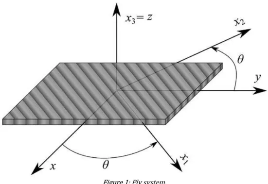
The laminate is composed by a set of layers or plies of fiber-reinforced composites with unidirectional fibers stacked in a defined sequence (layup). Each lamina can be treated macroscopically as orthotropic material in the local axis system (x1, x2 , x3 ), with the local axis x1 parallel to the fiber orientation, as illustrated in Figure 1. The local system is also known as material or ply system.
Figure 1: Ply system.
Under normal service conditions, the mechanical behavior of composite materials prior to failure can be considered linear elastic (Jones, 1999). Therefore, the generalized Hooke's Law can be used to obtain the stress-strain relationship in the local system of the ply. For a plane stress condition, the constitutive relation is given by:
1 11 12 1
2 12 22 2 1 1
12 66 12
0 0
0 0
Q Q Q Q
Q
Q
(1)
where 1 and 1 are the stress and strain vectors at local ply system and Q is the elastic constitutive matrix, whose terms are given by:
1 12 1 2
11 12 11 66 12
12 21 12 21 12 21
1 1 1
E E E
Q Q Q Q G
(2)
1 21 12
1
E E
(3)
In structural analysis, it is necessary to transform the stress from the ply axis to the global:
T
T QT Q (4)
where the transformation matrix (
T
) is given by2 2
2 2
2 2
cos sin sin cos
sin cos sin cos
2sin cos 2sin cos cos sin
T (5)
Laminated plates and shells can be analyzed through the Classical Laminated Theory - CLT (Barbero, 2011) which represents application of the Kirchhoff-Love theory to laminated structures. According to kinematic hypotheses of CLT, the strains () at a point inside the laminate can be related with the midplane strains by:
0
0 0
0
x x x
y y y
xy xy xy
z z
(6)
where z is the coordinate of the point, 0 corresponds to the membrane strains and represents the laminate curvatures.
The internal forces and moments are obtained integrating through the laminate thickness:
/2 /2 h x x y y h xy xy N N dz N
N (7) /2 /2 h x x y y h xy xy MM z dz
M
M (8)where
h
is the laminate thickness. Thus, the expression relating internal forces and moments to generalized strains of the laminate can be written as (Reddy, 2004; Daniel and Ishai, 2006):0 11 12 16 11 12 16
0 12 22 26 12 22 26 16 26 66 16 26 66 11 12 16 11 12 16 12 22 26 12 22 26 16 26 66 16 26 66
x x y y xy xy x y xy
N A A A B B B
N A A A B B B
N A A A B B B
M B B B D D D
M B B B D D D
M B B B D D D
0 0 x y xy
N A B
M B D
where
1 1 2 2 1 1 3 3 1 1 1 2 1 3 Nij ij k k k k
N
ij ij k k k
k N
ij ij k k k
k
A Q z z
B Q z z
D Q z z
(10)where
A
,B
andD
are the extensional, membrane-bending coupling and bending stiffness matrices, respectively. The terms of the ABD matrix depend on the laminate thickness, fiber orientation, stacking sequence and material properties. It is important to note thatB
0
for symmetric laminates and the membrane (in-plane) and bending (out-plane) responses are uncoupled for these laminates.3 LOCAL BUCKLING OF COMPOSITE COLUMNS
The local buckling is characterized by the instability of the elements that form the column cross-sections, that is, instability of plates, without translation of the axis of the column. The analysis of composite columns of fiber-reinforced polymers is usually performed by modeling the individual components of the structure, considering the flexibility of the connection between them. Thus, in this type of simulation each part of the cross-section is modeled as a plate and analyzed independently (Qiao, Davalos and Wang, 2001).
The simplest, commonly used approach, including some design guides, assumes simply supported conditions (SS) and/or a free edge and another simply supported (FS) to analyze the individual plates. The solutions for rectangular orthotropic long plates compressed in the main directions subjected to these conditions are given by (Barbero, 2011):
2 12 66 22 11 , 2 22 22 2 2 cr SS D D D D P D D b (11)
66 , 2 12 cr LS D P b h (12)
where
b
is the width of a flange or a web andh
is the wall thickness.According to Kollár (2014), the approach described above is considered a conservative estimate of the local buckling load, since the effect of the restriction of rotation on the long edges of the plate is neglected.
Kollár (2002a, 2002b, 2003) developed explicit expressions to evaluate of the local buckling load of fiber-reinforced beams and columns with open and closed thin-walled cross-sections (box, I, C, Z and L members) considering that these members are composed by a set of elastically restrained plates. In the approach described by Kollár (2003) initially, the local buckling critical loads of the plates that compose the cross-section are determined considering the simpler approach, previously described, assuming the SS or FS conditions according to the analyzed cross-section.
For I-member, if the web is simply supported at both edges and the flanges are simply supported along one edge and free at the other edge, the critical loads of the flange (
N
cr f, ) and the web (N
cr w, ) are determined from Eq. (11) and Eq. (12), respectively.If
Ncr f,
a11 f
Ncr w,
a11 w,the web restrains the rotation of the flange. In this way, the critical buckling load is calculated from the expression shown in the second line of Table 1, in which the spring constantk
is given by Kollár (2003):
, 11 22 , 111
1
2
cr f f
w cr w w
N
a
cD
k
b
N
a
where
c
2
, a11 is the tensile compliance of the wall segment and bw is the web width. Note that, when the flangesand the webs have identical thicknesses and layups,
a11 f
a11 w.If
Ncr f,
a11 f
Ncr w,
a11 w, the flanges restrain the rotation of the edges of the web. Thus, the critical buckling load is determined from the expression shown in the first line of Table 1, in which the torsional stiffness (GIt) is given by Kollár (2003):
, 11 66
, 11
4
1
cr w wt f
cr f f
N
a
GI
D b
N
a
(14)where
b
f is the flange width.Table 1: Buckling load for long orthotropic plates (Adapted from Kollár (2003).
Boundary conditions Buckling load Nx,cr
2
2
11 22 12 66
2 2 1 4.139 2 0.62 2
y
D D D D
L
11 22 2 11 22 2 7 1 115.1 1 6 1 1
1 4.12 for 1
1
15.1 1 6 1
for 1 y
y
K
D D K
L
K
D D K
L K where:
1/ 1 10
for plates with edges rotationally restrained by springs;
'1.2
1 / 1 0.61
for plates with edges rotationally restrained by stiffeners;
22
/
yD
kL
and
'
D L
22 y/
GI
t
12
/ 2
66 12D
D
D
and 1 / 1
7.223.55
2 66 12
/ 11 22K D D D D
y
L
is the width.Kollár (2003) addresses the effect of the restriction for several sections (box, I, C, Z and L members). For C members, the same expressions developed for profile I are applied, however, in Eq. (13) the factor 1 / 2 is omitted because the web restrains. It is also interesting to note that for I members we consider
b
f/ 2
in all expressions. These expressions were included in an appendix of the Italian standard (CNR, 2008) to determine the local buckling load of pultruded I-sections.To determine the closed-form equations, Cardoso (2014) used the Rayleigh Quotient method. In this method, the bending strain energy (
U
) and the work produced by the compressive load (T
) are calculated assuming an approximate deflection shape (w ) corresponding to the expected buckling mode, and the critical load per unit width (N
cr l,) is obtained from the condition of neutral equilibrium (U
T
):2 2 2
2 2 2 2 2
11, 2 22, 2 12, 2 2 66, 2 2 1 , 2 1 2 4 i i n
i i i i i
i i i i
i S i i i i i i
cr l n
i
i S i
w w w w w
D D D D dxdy
x y x y x y
N w dxdy x
(15)in which
i
is the index referring to each of the nplates of the cross-section andS
is the plate surface area.Cardoso (2014) adopted double-sinusoidal and polynomial-sinusoidal functions, both addressing the end conditions and rotation compatibility between adjacent plates. Thus, in general, for each constituent plate, the assumed buckling shapes are given by:
,
sin
x
w x y
f y
l
(16)where x is the longitudinal coordinate,
y
is the transverse coordinate,f y
is chosen to be either a polynomial or sinusoidal function andl
is the half-wave buckling length.The approximate functions
f y
, adopted by Cardoso (2014), for webs (w ) and flanges (f) of I and C members are:
w sinw w b y f y b
(17)
f
f y
y
(18)where is the rotation at the intersection between adjacent plates.
From these approximate functions, we obtain the strain energy in bending (
U
) and the work produced by the compressive load (T
) for each cross section. Then, from Eq. (15), the critical load per unit width,N
cr l, , is determined, and thenF
cr l, can be obtained by dividingN
cr l, by the plate thickness (t):
2 2 1 , 12 21 12 1 cr l w E h F k b (19)
where
k
is the shape-specific buckling coefficient. The critical buckling coefficient (kcr ) to be used in thisexpression is obtained minimizing
k
with respect to the buckling length (l
). For channel members, the critical buckling coefficient is given by:
2 12
12 12 21
2 1 1
2 3 2 3 1
2 4 1 4 1
2
1 4 / 3
1 4 / 3
cr
E G
E E E
k E (20)
where
b
f/ .
b
wIn this paper, the local buckling loads of laminated channel columns obtained using the individual plate approach considering the elastic constraints proposed by Kollár (2003) and the energy approach developed by Cardoso (2014) will be compared with the finite element results. It is important to note that both approaches were proposed for columns of orthotropic materials whose main axis (x1 ) is aligned with the column axis. Therefore, they have been successfully used for pultruded columns, but their application to laminated columns has to be assessed.
3.1 Effective Properties
The bending stiffness matrix (
D
) for orthotropic materials is given by:1 12 1
12 21 12 21
11 12 3
12 1 2
12 22
12 21 12 21 66 12 0 1 1 0 0 0
12 1 1
0 0 0 0 E E D D E E h D D D G
D (21)
Thus, this matrix depends only on the stiffness parameters D11, D12, D22 and D6 6 , since the other parameters are zero. In addition, Eq. (19) and Eq. (20) were written directly in terms of the material parameters in order to simplify the numerical evaluation.
Unfortunately, the bending stiffness matrix of a general laminate is fully populated (D1 6 0 and D2 6 0 ) presenting a coupling between bending and torsion. For these laminated plates there are no analytical expressions to evaluate the buckling loads. However, approximate solutions can be found neglecting the bending-torsion coupling.
The equivalent properties can be obtained from the terms of bending stiffness. From Eq. (21) and Eq. (3):
2
2
11 22 12 11 22 12 66
1 2 12
3 3 3
22 11
12 D D D 12 D D D 12D
E E G
h D h D h
(22)
12 12
12 21
22 11
D D
D D
(23)
It is important to note that for balanced or cross-ply symmetric laminates, the terms D16 and D26 are small and Eqs. (22) and (23) lead to good results. The computation of the equivalent material properties corresponds to a homogenization process resulting in a fictitious orthotropic material with the same bending stiffness. The homogenization based on Eq. (21) will be called Stiffness Approach (SA).
For angle-ply laminates, the terms D16 and D26 are non-zero. Thus, the expressions developed for orthotropic materials do not provide satisfactory results for these laminates, especially when they have a small number of plies. Another approach that can be used is to obtain the equivalent elastic properties from the inverse of bending stiffness matrix
D
(Flexibility Approach - FA):12
3 3
1 1
11 12 16 3
1 12
12 22 26 3 3
1 2
16 26 66
3 12 12 12 0 12 12 0 12 12 0 0
h E h E
h
h E h E
h G
D (24)
1 2 12
3 3 3
11 22 66
12 12 12
E E G
h h h
(25)
12 12
12 21
11 22
(26)
The terms D16 and D26, neglected in the stiffness approach, will be considered indirectly in the inversion of matrix
D
. Therefore, the flexibility approach may present better results for angle-ply laminates than the previous approach based on stiffness.4 FINITE ELEMENT FORMULATION
The finite element studies were performed using the software ABAQUS (Simulia, 2012). The columns considered in this work are based on the thin-walled channel-section (Figure 2) previously studied by Debski, Kubiak and Teter (2013b) with
b b
f/
w
0.5
. These columns were made of the Hexcel's HexPly M12 Carbon-epoxy, whose mechanical properties are presented in Table 2, where Xt is the longitudinal tensile strength, Yt isthe transverse tensile strength, Xc is the longitudinal compressive strength, Yc is the transverse compressive
strength, and
S
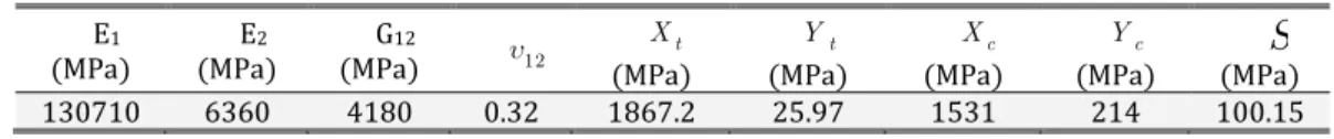
is the shear strength.Table 2: Mechanical properties of Hexcel’s HexPly M12(Debski, Kubiak and Teter, 2013b).
E1
(MPa) (MPa) E2 (MPa) G12 12 Xt
(MPa)
t
Y
(MPa)
c
X
(MPa)
c
Y
(MPa) (MPa)
S
130710 6360 4180 0.32 1867.2 25.97 1531 214 100.15
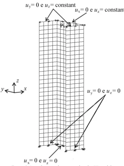
Figure 3: Boundary conditions used in the FE model.
The columns were discretized using 480 quadratic (8-node) shell elements with reduced integration (S8R). Three different symmetric layups were considered: L1 [0/-45/45/90]s, L2 [0/90/0/90]s and L3 [45/-45/90/0]s. An initial finite element model was proposed to represent the conditions of the tests performed by Debski, Kubiak and Teter (2013b). Thus, a concentrated load was applied to the centroid of the cross section and an additional constraint was considered at the top of the columns to make the axial displacement constant along the length. The transverse displacements along x-axis and y-axis were restrained in the flanges and web, respectively. The vertical displacement (z-axis) is constant in the nodes of the column upper end (Figure 3). This condition is enforced using multi-point constraint equations.
Columns are affected by initial imperfections related to the manufacturing and assembly tolerances, which reduce the load capacity of the structure. The FRP pultruded profiles present geometric imperfection in the form of out of straightness, twist, angularity, etc, and the presence of these imperfections have to be included in the model (Ascione, 2014)
Thus, in order to evaluate the behavior of real columns, the nonlinear analysis was performed considering initial geometric imperfections. Generally, the imperfect geometry of the structure is represented by linear combination of its buckling modes (i):
1
n imp perf i i
i
x x (27)
where
x
impandx
perf are the coordinates of the points that define the geometry in the imperfect and perfect configuration, respectively, and i is the amplitude of the imperfection related to the buckling modes i, sinceDebski, Kubiak and Teter (2013b) considered only the first buckling mode to represent the geometric imperfections, with an amplitude equal to 10% of the wall thickness (
0.1
h
). The same geometric imperfection was initially adopted in the present work. The nonlinear analyses were carried-out using the arc-length method (RIKS) (Nali and Carrera, 2012) in order to trace the complete equilibrium paths.4.1 Effect of the composite layup
Initially a series of linearized buckling analysis was carried-out and the obtained local buckling critical loads (Pcr) are presented in Table 3, along with the results of Debski, Kubiak and Teter (2013b). It can be noted that
there is an excellent agreement for all layups, since the largest difference observed was 4.2% for L1 column, while the differences for columns L2 and L3 were less than 1%.
Table 3: Critical loads.
Layup
Debski, Kubiak and Teter (2013b) Numerical
Difference (%)
,exp cr
P
(kN)P
cr FE,(kN)
, cr FE
P
(kN)
A B C C-A C-B
L1 2.8483 2.9772 2.9725 4.18 -0.158
L2 2.2748 2.2823 2.2749 0.004 -0.325
L3 4.3697 4.4024 4.4059 0.822 0.080
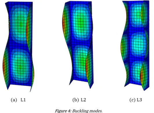
These results clearly show the influence of the column layup on critical load values, as critical load for L3 column being about 90% greater than that of the L2 column. The first buckling modes, obtained from the proposed model, for the three layups are presented in Figure 4. It is possible to observe that as the critical loads for L1 and L2 column are relatively close, their buckling modes are also similar, being composed of two half-waves.
Figure 4: Buckling modes.
proposed model is less stiff. A possible justification for this divergence is that Debski, Kubiak and Teter (2013b) used linear (4-node) shell elements with reduced integration (S4R), while quadratic elements (S8R) with the same mesh discretization were used in this work.
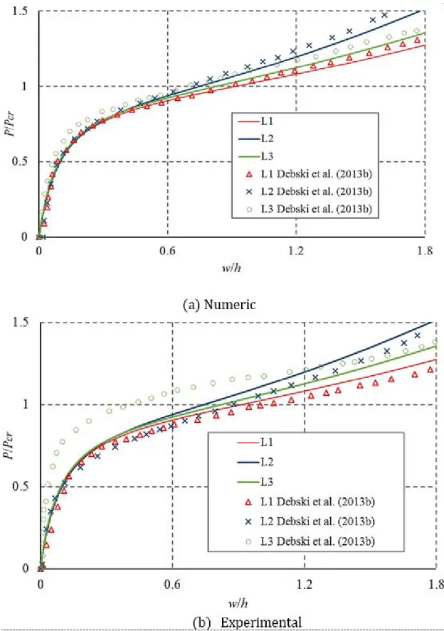
Figure 5: Equilibrium paths of the imperfect columns.
(angle-ply). This may be explained by the presence of terms D16 and D26 in the bending stiffness matrix of the angle-ply columns.
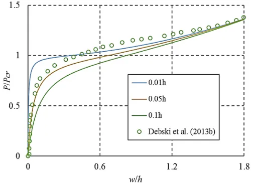
The nonlinear equilibrium paths of the L1 and L2 columns obtained in this paper are also in good agreement in relation to the experimental results of Debski, Kubiak and Teter (2013b), as depicted in Figure 5(b). However, it has been found that for column L3, the imperfection of 0.1h , adopted by the aforementioned authors, does not satisfactorily represent the actual column. In this way, a study of the sensitivity of the columns to geometric imperfections was carried out and the obtained results are presented in Figure 6. From the study, it was verified that the amplitude of L3 column is closer to 5% of the wall thickness (0.05h ). In addition, this analysis indicates that the local buckling of thin-walled laminated columns may be characterized as a stable symmetric bifurcation, with small imperfection sensitivity.
Figure 6: Effect of initial imperfections on L3 column.
4.2 Effect of the composite layup
The influence of the laminate thickness (
h
) was studied increasing the number of plies (n). This study was carried-out for the L1 and L2 columns, which presented the smaller critical loads. The buckling loads computed using the finite element model validated in the previous section is presented in Table 4.It can be observed that as the number of layers increases, the critical loads of the columns increases significantly. This was an expected result since the slenderness of the columns is considerably reduced when the wall thickness increases.
Table 4: Critical loads for different thicknesses.
Layup n
h
(mm) Pcr(kN)L1
8 1.048 2.97
16 2.096 27.83
24 3.133 92.64
32 4.192 210.98
L2
8 1.048 2.27
16 2.096 18.70
24 3.133 61.93
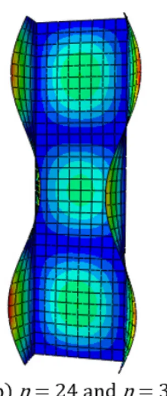
The buckling modes of L1 and L2 columns are shown in Figure 7 and Figure 8, respectively. It is interesting to note that the increase of the laminate thickness changes the buckling modes, with the number of half-waves increasing from 2 to 3.
Figure 7: Buckling modes of L1 column.
Figure 8: Buckling modes of L2 column.
(2013b). Thus, this amplitude was adopted for the following analyzes, maintaining the shape of the first buckling mode.
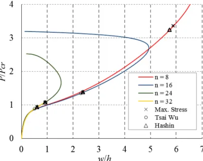
As the wall thickness increases, material failure may become an issue for column design. This effect was studied initially using the First Ply Failure (FPF) approach considering the Maximum Stress (Daniel and Ishai, 2006), Tsai-Wu (Tsai and Wu, 1972), and Hashin (1980) failure criteria.
The normalized load-displacement curves obtained for columns L1 and L2 are shown respectively in Figure 9 and Figure 10, where the symbols indicate where material failure occurred according to each criterion. The laminate thickness presents little influence in the normalized curves up to the buckling load (P / Pc r 1), but a large influence after that, with the structure presenting smaller transverse displacements.
Figure 9: Load-displacement curves for L1 columns.
Figure 10: Load-displacement curves for L2 columns.
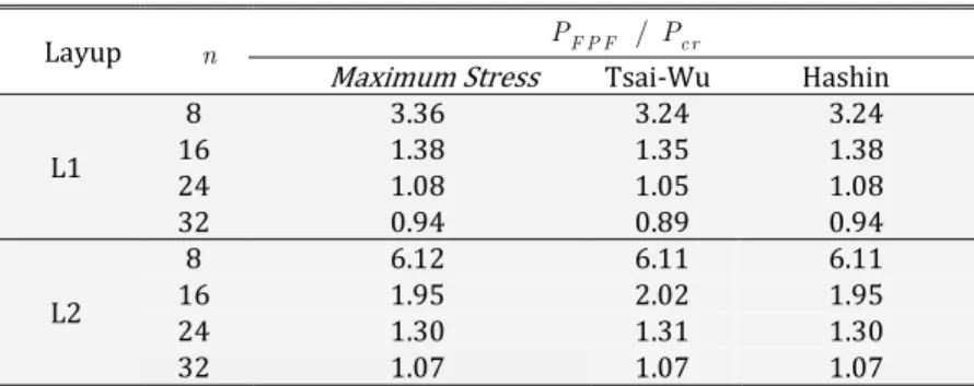
Table 5 presents the comparison of the load corresponding to FPF (PFPF) with respect to the critical buckling
load (Pcr). These results show that the different failure criteria considered in this work presented similar behavior
with negligible difference between them. In addition, it can be noted that in the L1 column (angle-ply), by doubling the number of plies to
n
16
, for example, post-critical resistance decreased approximately 40%, whereas for L2 column (cross-ply) the reduction was smaller (around 30%).As expected, as the wall thickness increases, material failure becomes more important, as the ratio PF P F / Pcr steadly decreases. However, the material failure became dominating over the stability only for the L1 column (angle-ply) with
n
32
. For L2 column (cross-ply) a larger thickness would be required to this occur. Therefore, stability is the major issue in the design of laminated columns.Table 5: PFPF /Pcr for different failure criteria.
Layup n PF P F / Pcr
Maximum Stress Tsai-Wu Hashin
L1
8 3.36 3.24 3.24
16 1.38 1.35 1.38
24 1.08 1.05 1.08
32 0.94 0.89 0.94
L2
8 6.12 6.11 6.11
16 1.95 2.02 1.95
24 1.30 1.31 1.30
32 1.07 1.07 1.07
Figure 11 and Figure 12 show the failure modes of L1 and L2 column with different thicknesses, with the red color indicating where the failure index is larger. It can be noted that the first ply failure occurred in the web for all cases considered in this work.
Figure 12: Failure modes of the L2 columns for different criteria.
4.3 Progressive Failure
In order to assess the importance of progressive failure in the load carrying capacity of composite channel columns, the First Ply Failure loads obtained from geometric nonlinear analyses will be compared with the ultimate failure loads obtained from nonlinear analyses considering the geometric and material nonlinearities. The same geometric imperfections with amplitude equal to 0.1h are used in both cases.
The material nonlinearity is represented by the continuous damage model for fiber-reinforced composites of ABAQUS (Simulia, 2012), which uses Hashin (1980) as the damage initiation criterion. The damage evolution model is based on the approach proposed by Camanho and Dávila (2002).
The damage model was used in L1 and L2 columns only with
n
32
(t 4.1 9 2m m ), since progressive failure is more important for thicker laminates. The T300/1034-C carbon fiber reinforced epoxy (Miamí et al, 2006), whose mechanical properties and fracture toughness are shown in Table 6 and Table 7, respectively, will be use in the analysis, since the damage parameters of the previous material are not known. In this paper, the viscosity coefficients were considered as1
e
5
for all analyses.Table 6: Mechanical properties of the T300/1034-C (Ascione, 2014).
E1
(GPa) (GPa) E2 (GPa) G12 12 t X
(MPa)
t
Y
(MPa)
c
X
(MPa)
c
Y
(MPa) (MPa)
S
146.80 11.47 6.10 0.29 1730 66.50 1379 268.2 58.2
Table 7: Fracture toughness of the T300/1034-C (Ascione, 2014)
Gft (J/m2) Gfc (J/m2) Gmt (J/m2) Gmc (J/m2)
89830 78270 230 760
Figure 13: Load-displacement curves for L1 and L2 columns with
n
32
.Additionally, the values of the buckling load, the First Ply Failure load using Hashin criterion and the ultimate load determined from the damage model are presented in Table 8. These results show that the increase in the failure load due the consideration of progressive failure depends on the column layup. However, even for moderately thick column with a large number of plies, the increase in the failure load is small and the consideration of the FPF approach is not overly conservative. It is important to note that the FPF approach is based on elastic analyses and do not require the evaluation of the complex material parameters of the continuum damage model.
Table 8: Ultimate failure load using the damage model.
Layup Pcr (kN) PFPF (kN) Pu (kN) Pcr / PF P F Pu /Pcr Pu / PF P F
L1 248.68 228.78 243.70 0.92 0.98 1.07
L2 174.67 160.70 188.64 0.92 1.08 1.17
4.4 Closed-form expressions for local buckling
The Finite Element Method is a powerful tool for research, analysis and design of complex structures, but simpler methods may be more practical for everyday use, including preliminary design. Therefore, the applicability of Eq. (11) and Eq. (12) and of the closed-form expressions proposed by Kollár (2003) and Cardoso (2014) will be assessed in the following. The numerical calculations performed in the determination of the critical loads by means of these expressions were implemented in MATLAB software.
The expressions used to determine local buckling of columns are functions of stiffness parameters based on elastic properties. For pultruded columns, obtaining these material parameters is simpler, but for laminated columns it becomes necessary to determine equivalent properties that depend on the column layup.
In this way, the equivalent properties (E1,E2,G1 2 , 12 and 21) may be obtained using two different
approaches, described in Section 3.1: The Stiffness Approach (SA), neglecting the terms D16 and D26, and the Flexibility Approach (FA), indirectly considering these terms.
Table 9 and Table 10 present the comparison of the local buckling critical loads determined from Eq. (11) and Eq. (12) and the expressions proposed by Kollár (2003) and Cardoso (2014) with the results obtained experimentally by Debski, Kubiak and Teter (2013b) for the L1 and L2 columns (0.5).
Table 9: Critical loads using the Stiffness Approach (SA).
Layup
cr
P (N)
Difference (%) Debski, Kubiak and Teter
(2013b) Eqs. (11) and (12) (2003) Kollár Cardoso (2014)
A B C D B-A C-A D-A
L1 2848.3 1848.2 2905.2 3279.4 -35.1 2.0 15.1
L2 2274.8 418.1 2299.1 2370.6 -78.9 1.1 4.2
Table 10: Critical loads using the Flexibility Approach (FA).
Layup
cr
P (N)
Difference (%) Debski, Kubiak and Teter
(2013b) Eqs. (11) and (12) Kollár (2003) Cardoso (2014)
A B C D B-A C-A D-A
L1 2848.3 1661.2 2658.8 2986.7 -41.7 -6.6 4.9
L2 2274.8 418.1 2299.1 2370.6 -78.9 1.1 4.2
With respect to the evaluation of the equivalent material properties, the results for column L2 were not influenced by the used approach, which was expected since the terms D16 and D26 are zero for the symmetric cross-ply laminates. On the other hand, for L1 (angle-cross-ply) column, the critical load was significantly reduced when these terms are considered using the Flexibility Approach (FA).
The results obtained using the Kollár (2003) equations were satisfactory for both columns, presenting differences less than 7% when compared to the experimental results of Debski, Kubiak and Teter (2013b). However, it is interesting to note that for column L1, when considering the terms D16 and D26, there was an increase in the difference between the calculated critical load and the load obtained experimentally. This increase was due to the reduction of the approximate critical load.
An important aspect that should be emphasized is that, in addition to the composite layup, the geometric relations of the cross section also strongly influence the accuracy of the approximate equations for local buckling load. Cardoso (2014) performed a comparison between the results determined from the equations proposed in his work and the Finite Strip Method. For pultruded channel sections, with typical commercial sections (
0.15
b
f/
b
w
0.53
), the mentioned author observed differences of up to 10%.In the present work, the applicability of Cardoso (2014) equations for L1 and L2 columns with 0.5was verified initially and the largest difference obtained was 15% for the L1 column by neglecting the terms D16 and D26 (Table 10). However, this difference was reduced to 5% when these terms were considered using the Flexibility Approach (FA).
Then, in order to verify the influence of the geometric relations of the cross section, finite element analyses were performed using the shell model validated in this paper for L1 and L2 columns with
0.20
b
f/
b
w
0.55
and the results obtained were compared with those determined from Eq. (11) and Eq.(12) and the expressions proposed by Kollár (2003) and Cardoso (2014).
Figure 14: Pcr versus
for column L1.Figure 14 also shows the local buckling critical loads determined from the equations of Kollár (2003) for L1 column (angle-ply) using the two approaches. The results obtained by the Flexibility Approach (FA) showed a better agreement with the numerical results, being the largest difference of approximately 12%. It is also important to note that for some geometric relations (
0.45
b
f/
b
w
0.55
) the results obtained by the Flexibility Approach are very close to the FE results, with differences smaller than 4%. On the other hand, larger errors were obtained (up to 19.5%) when the effects of D16 and D26were neglected (Stiffness Approach).In general, the Flexibility Approach (FA) presented better results for the evaluation of the local buckling load using both Cardoso (2014) and Kollár (2003) equations. Furthermore, it is interesting to note that this approach generally leads to more conservative results (smaller buckling loads) than the Stiffness Approach (SA), since there is a reduction of the critical load when considering the terms D16 and D26. Therefore, this approach is recommended for use with both Cardoso (2014) and Kollár (2003) equations. On the other hand, as the results obtained from Eq. (11) and Eq. (12) are already overly conservative, it seems more appropriate to use Stiffness Approach (SA) with these equations.
Figure 15: Pcr versus
for column L2.The results determined using Cardoso (2014) equations showed good agreement with the numerical results, with the largest difference being equal to 9% for 0.55. On the other hand, the results obtained by Kollár (2003)
equations for
0.20
b
f/
b
w
0.35
present quite significant differences, overestimating the buckling load up to 80%. However, these differences are significantly reduced as
b b
f/
wincreases, with lightly conservative results obtained for large
.The results indicate that when flange width (
b
f ) is very smaller than web width (bw ), the approximation ofthe elastic restraints on the edges of the adjacent plates that form the channel section are not accurately evaluated. This problem was observed for both columns, but was more pronounced for the angle-ply column (L2).
5 CONCLUSIONS
This work presented a study of the behavior, performance and failure of laminated columns with channel cross-sections. Initially, a shell finite element model was validated using experimental and numerical results available in the literature. As good agreement was obtained, this model was used in the subsequent studies.
The results highlighted the influence of the column layup on the local buckling loads, post-critical behavior and ultimate failure load, showing the importance of using optimization techniques in the design of laminated columns (Rocha et al., 2014; Barroso et al., 2017). With respect to the effect of laminate thickness and number of plies, the results showed not only the increase of the buckling load, but also changes in the shape of the buckling modes. In addition, the importance of the material failure increases with the number of plies and the post-critical behavior presents snap-backs due to mode jumps at smaller relative displacements. However, these mode jumps occurred for loads larger than the critical and material failure loads in all cases, with the structure exhibiting a stable symmetric bifurcation behavior.
Acknowledgements
The financial support by CNPq (Conselho Nacional de Desenvolvimento Científico e Tecnológico) and FUNCAP (Fundação Cearense de Apoio ao Desenvolvimento Científico e Técnologico) is gratefully acknowledged.
References
Akbulut H., Gundogdu O. and Sengül M. (2010) Buckling behaviors of laminated composite stepped flat columns. Finite Elements in Analysis and Design 46: 1061-1067.
Ascione F. (2014) Influence of initial geometric imperfections in the lateral buckling problem of thin walled pultruded GFRP I-profiles. Composite Structures 112:85-99.
Barbero E. J. and Tomblin J. (1994) A phenomenological design equation for FRP columns with interaction between local and global buckling. Thin-Walled Structures 18: 117-131.
Barbero E. J and DeVivo L. R. (1999) Beam-Column design equations for wide-flange pultruded structural shapes. Journal of Composite for Construction 3:185-191.
Barbero E. J. (2000) Prediction of Buckling-Mode Interaction in Composite Columns. Mechanics of Composite Materials and Structures 7: 269-284.
Barbero E. J. (2011) Introduction to composite materials design. 2nd ed. CRC Press, Boca Raton.
Barroso E. S, Parente Jr. E. and Melo A. M. C. (2017). A hybrid PSO-GA algorithm for optimization of laminated composites. Structural and Multidisciplinary Optimization 55: 2111-2130.
Camanho P. P. and Dávila C. G. (2002) Mixed-mode decohesion finite elements for the simulation of delamination in composite materials. NASA/TM-2002-211737, Langley; 2002.
Cardoso D. C. T., Harries K. A. and Batista E. M. (2015) Compressive Local Buckling of Pultruded GFRP I-Sections: Development and Numerical/Experimental Evaluation of an Explicit Equation. J. Composites Construction 19(2): 04014042-1-12.
Cardoso D. C. T., Harries K. A. and Batista E. M. (2014) Compressive strength equation for GFRP square tube columns. Composites: Part B 59:1-11.
Cardoso D. C. T. (2014) Compressive strength of pultruded glass-fiber reinforced polymer (GFRP) columns. Thesis, Universidade Federal do Rio de Janeiro.
CNR (2008), “CNR-DT 205/2007: Guide for the design and construction of structures made of FRP pultruded elements”, Rome.
Daniel I. M. and Ishai O. (2006) Engineering mechanics of composite materials. 2nd ed. Oxford University Press, New York.
Debski H., Kubiak T. and Teter A. (2013a) Buckling and postbuckling behavior of thin-walled composite channel section column. Composite Structures 100:195-204.
Debski H., Kubiak T. and Teter A. (2013b) Experimental investigation of channel-section composite profiles behavior with various sequences of plies subjected to static compression. Thin-Walled Structures 71:147-154.
Hashin Z. (1980) Failure criteria for unidirectional fiber composites. Journal of Applied Mechanics 47:329-334.
Jones R. M. (1999) Mechanics of composite materials. 2nd ed. Taylor & Francis.
Knight N. F. (2006) User-defined material model for progressive failure analysis. NASA/TM-2006-214526, Virginia.
Kollár L. P. (2002a) Buckling of unidirectionally loaded composite plates with one free and one rotationally restrained unloaded edge. Journal of Structural Engineering 128(9):1202-1211.
Kollár L. P. (2002b) Discussion of “Local buckling of composite FRP shapes by discrete plate analysis” by Pizhong Qiao, Julio F. Davalos, and Jialai Wang. Journal of Structural Engineering 128(8):1091-1093.
Kollár L. P. (2003) Local buckling of fiber reinforced plastic composite structural members with open and closed cross sections. Journal of Structural Engineering 129(11):1503-1513.
Kollár L. P. (2014) Buckling of rectangular composite plates with restrained edges subjected to axial loads. Journal of Reinforced Plastics and Composites 33(23): 2174–2182.
Kubiak T. and Mania R. J. (2016) Hybrid versus FR laminate channel section columns – Buckling and post buckling behavior. Composite Structures 154:142-149.
Lapczyk I. and Hurtado J. A. (2007) Progressive damage modeling in fiber-reinforced materials. Composites Part A: Applied Science and Manufacturing 38:2333–2341.
Miamí P., Camanho P. P., Mayugo J.A. and Dávila C.G. (2006) A thermodynamically consistent damage model for advanced composites. NASA/TM-2006-214282, Virginia.
Nali P. and Carrera E. (2012) A numerical assessment on two-dimensional failure criteria for composite layered structures. Composites: Part B: Engineering 43:280-289.
Nunes F., Silvestre N. and Correia J. R. (2016a)Structural behaviour of hybrid FRP pultruded columns. Part 1: Experimental study. Composite Structure 139:291-303.
Nunes F., Silvestre N. and Correia J. R. (2016b)Structural behaviour of hybrid FRP pultruded columns. Part 2: Numerical study. Composite Structure 139:304-319.
Puente I., Insausti A. and Azkune M. (2006) Buckling of GFRP Columns: An Empirical Approach to Design. Journal of Composites for Construction 10:529-537.
Qiao P., Davalos J. F. and Wang J. (2001) Local buckling of composite FRP shapes by discrete plate analysis. Journal of Structural Engineering 127(3):245-255.
Qiao P. and Shan L. (2005) Explicit local buckling analysis and design of fiber-reinforced plastic composite structural shapes. Composite Structures 70:468-483.
Reddy J. N. (2004) Mechanics of laminated composite plates and shells: Theory and Analysis. 2nd ed, Boca Raton; CRC Press.
Rocha I. B. C. M, Parente Jr. E. and Melo A. M. C. (2014) A hybrid shared/distributed memory parallel genetic algorithm for optimization of laminate composites. Composite Structures 107: 288-297.
Sleight D. W. (1999) Progressive failure analysis methodology for laminated composite structures. NASA/TP-1999-209107, Langley.
Tsai S. W. and Wu E. M. (1972) A general theory of strength for anisotropic materials. Technical report. Air Force Materials Laboratory.
Turvey G. J. and Zhang Y. (2006) A computational and experimental analysis of the buckling, postbuckling and initial failure of pultruded GRP columns. Computers and Structures 84:1527-1537.