Stress distribution in a photoelastic model
resulting from intrusion of mandibular incisors
using Ricketts utility arch
Cristiane Aparecida de Assis Claro*, Jorge Abrão**, Sílvia Augusta Braga Reis***, Dalva Cruz Laganá****
Objective: This study aimed to investigate stress distribution in a photoelastic model generated by Ricketts Utility Arch (RUA), also known as Ricketts base arch, for intrusion of mandibular incisors. Stresses in the root thirds of each incisor were compared and the existence of differences in the concentration of stresses between the incisors was also examined. Methods: Fifteen intrusion RUAs were fabricated. Activation force was set at 50 gf in the midline region. The photoelastic model was observed in a circular polariscope in dark field configuration and photographed. Frontal view photographs were analyzed and fringe orders recorded in each region. Weighted Kappa analysis was used to identify method repeatability. Comparison between stresses was performed by Kruskal-Wallis test and complemented by Dunn’s test at 5% alpha level. Results and Conclusions: Results showed that the major stress magnitudes were found in cervical regions. By comparing fringe orders between teeth the major stress magnitudes were found to be in the central incisors. Cervical regions and central incisors may therefore be more prone to resorption given their greater stresses.
Abstract
Keywords: Photoelasticity. Intrusion. Biomechanics. Root resorption.
* PhD in Orthodontics, Dental School, University of São Paulo. Assistant Professor, Discipline of Orthodontics, Department of Dentistry, University of Taubaté.
** Head Professor, Discipline of Orthodontics, Dental School, University of São Paulo.
*** PhD in Orthodontics, Dental School, University of São Paulo. MSc in Orthodontics, Metodista University of São Paulo. **** Head Professor, Discipline of Removable Prosthesis, Dental School, University of São Paulo.
INtROduCtION
Ricketts utility arch (RUA), also known as base arch, has been described as a resource to promote the intrusion of incisors in correcting overbite, mainly in the Bioprogressive technique.17,21 RUA effectiveness in obtaining real incisor intrusion has been confirmed.1,18 There have been reports,
however, that intrusion is but one contributing factor among others, such as incisor proclination and molar extrusion, which occur during overbite correction using RUA.
RUAs are usually made out of blue temper chro-mium-cobalt alloy (Elgiloy®), whose properties re-semble those of steel, but with increased formability.
How to cite this article: Claro CAA, Abrão J, Reis SAB, Laganá DC. Stress
distribution in a photoelastic model resulting from intrusion of mandibu-lar incisors using Ricketts utility arch. Dental Press J Orthod. 2011 Sept-Oct;16(5):89-97.
» The authors report no commercial, proprietary, or inancial interest in the
Elgiloy composition comprises 40% cobalt, 20% chromium, 15% nickel, 15.8% iron, 7% molyb-denum, 2% manganese, 0.16% carbon and 0.04% beryllium.13 After RUA fabrication heat treatment is not recommended as it would lead to increased force generation by the arch.16,17
RUAs are double binary intrusion arches fea-turing a greater moment in molars due to a caudal angle, and another moment in the anterior region, caused by lingual torque in the incisors. Given that the moments occur in the same direction, balance forces are summed. However, if anterior torque is applied buccally, moment will be cre-ated in opposition to the molar. Therefore, since molar and incisor moments will be in opposite directions, intrusion force will be diminished in the anterior region. If anterior buccal torque mo-ment is greater than molar momo-ment, incisors may undergoextrusion.3
Stress distribution resulting from intrusion RUAs was verified by another study,19 which iden-tified the formation of photoelastic fringes around incisor roots and uniform results between teeth. Considering that the aforementioned study made use of a 4x2 system and a stainless steel RUA, the authors of this study decided to examine the stress-es produced by an intrusion RUA fabricated with chromium-cobalt alloy, with the aid of posterior anchorage, using a rectangular sectional archwire.
This study analyzed stress distribution in a photoelastic model resulting from an intrusion RUA, compared stress magnitudes in root third regions and checked stress uniformity in the four mandibular incisors.
MAtERIAL ANd MEtHOdS
Firstly, brackets (Ovation/Dentsply GAC In-ternational, New York, USA) were bonded with Super Bonder glue (Loctite, Barueri, Brazil) to artificial teeth (B2-306/Kilgore, Nissin, Kilgore International, Michigan, USA), and bands (Roth prescription / “A” company - San Diego, USA) were cemented to molars.
To simulate mandibular incisor overeruption, a rectangular 0.021 x 0.025-in stainless steel archwire was inserted with a pronounced 4 mm curve of Spee in the premolar region, in a method relatively similar to that of a previous study.7 A 0.021 x 0.025-in cross-section wire was used to ensure a reduction in the play of the wire in the bracket/tube slots.
A metal strip was shaped like a horseshoe and adapted onto a caulked glass plate so as to allow liquid wax #7 to be poured with the same width along the entire arch. This procedure was per-formed due to the fact that model thickness has a bearing on fringe formation:
Fringe order = δ/λ, where: » δ = relative delay, » λ = wave length.
And relative delay = δ = Kt(ε1–ε2) = (n1–n2)t, where:
» K = optical stress constant,
» ε1 – ε2 = difference between the principal strains,
» n1 – n2 = difference between refraction indices (birefringence),
» t = thickness of the material.
The set was bonded with Super Bonder glue inside a plastic pot. Blue silicone rubber (ASB-10 Blue/Polipox, São Paulo, Brazil) (300 ml) was mixed slowly with the catalyst (21 ml) to prevent the inclusion of air bubbles, and poured until the set was completely covered.
After 48 hours the wax was removed with hot water and detergent. To complete wax removal, a product called Remox (Vipi, Pirassununga, Bra-zil) was used. The cast was then washed and dried with compressed air.
with the aid of a glass rod, once again placed in the vacuum chamber for 30 minutes and allowed to rest for 24 hours.
After 72 hours the specimen was removed from the cast. It was, therefore, necessary to cut the cast in the cervical region of the crowns. Af-ter fabrication of a photoelastic patAf-tern, the arch was removed and a silicone impression of the crowns with brackets on was performed to serve as guidance in rebonding, in case any items fell off during the experiment.
Fifteen RUAs were fabricated, contoured with the help of diagrams (Tru arch form, “A” Com-pany, San Diego, USA) in the largest size of the mandibular arch. In Ricketts mechanics, RUAs are usually made of Blue Elgiloy® 0.016 x 0.016-in wire (Rocky Mountain, Denver, USA) since in the Bioprogressive technique bracket slot dimensions are 0.018 x 0.030-in.
Blue 0.016 x 0.022-in Elgiloy® wires (Rocky Mountain, Denver, USA) were utilized, since the slots of the brackets used in this study (Ova-tion/Dentsply GAC International, Bohemia, NY, USA) were 0.022 x 0.028-in. Brackets with 0.019 x 0.019-in slots could have been used. In-stead, however, since the author of another study19 had used 0.016 x 0.022-in slot brackets, using the same wire size would ultimately facilitate a com-parison between results.
The archwire form had 45° distal tipping, 15º distolingual rotation, 30º posterolingual torque, vertical deviation on the mesial side of the first molar tube and on the distal side of the lateral incisor,16 as well as anterior lingual torque.3,17
The steel 0.021 x 0.025-in archwire used to simulate the malocclusion was cut into two pos-terior sections (from distal side of second molars to mesial side of first premolars) and one anterior section (from distal right of lateral incisor to dis-tal side of left lateral). The posterior sections were kept as posterior anchorage.
A tension gauge (250/Correx, Haag-Streit AG, Koeniz, Switzerland) was used to measure the
forces in the intrusion arches. Gradation begins at 25gf and ends at 250gf. Initially, all intrusion arches should generate 50gf. Those that failed to exhibit such force had their caudal angles adjust-ed so that the force would reach 50gf.
After arch insertion, the model was studied in a circular polariscope (Eikonal Intrumentos Óp-ticos, São Paulo, Brazil) (Fig 1) set up with the following elements: Light source, light diffuser, polarizer, quarter wave plate, photoelastic pat-tern, quarter wave plate and analyzer. A camera (D70 Nikon, Melville, NY, USA) was mounted on a tripod and positioned in front of the analyz-er. The photoelastic pattern was embedded in a stress-free acrylic container containing mineral oil and placed on a turntable with markings to allow proper repositioning of the model.
The cubic container, built from virgin acrylic, was previously observed in the polariscope to as-certain the absence of residual stress, which might interfere with the observation of fringes in the model. After the absence of stress in the container had been verified, it was filled with mineral oil as it favors the observation of fringes in complex mod-els. For each arch replacement, removal of model from the container was carried out with the ex-aminer wearing gloves to avoid oil contamination.
After insertion of each arch, photographs were taken in frontal view. The photographs were tak-en by following certain criteria so that any com-parisons between them would not be affected by other variables.
During the experiment: (a) The same distance was kept between all polariscope components as they remained in position until the end of the ex-periment, (b) The angle between the photoelas-tic model and the camera lens was maintained, as well as (c) The aperture (f=8), speed (v=1/400s) and framework (0.45) of the camera.
In order for the model to be repositioned in the same location after insertion of every new arch, pre-existing markings on the turntable were positioned in such a way that the mesial surfaces of the first molars were made to coincide with the horizontal line while the midline coincided with the center line perpendicular to the aforementioned line.
The photographs were always taken at the same location while maintaining the same lighting conditions in the environment. The digital pho-tographs were exported to a computer and ana-lyzed using the zoom feature. Considering Table 1, fringe orders were recorded for all images and recorded in spreadsheets separated by tooth (42, 41, 31 and 32), apical, middle and cervical root thirds, mesial and distal surfaces.
Figure 2 shows one of the photographs of stresses generated by the arch and analyzed in the experiment.
Statistical method
In order to assess intraobserver agreement (re-peatability) of the method, five photographs were selected and all areas reassessed with a one-week interval. The values of fringe orders arising from such assessment were used along with the first analysis to calculate weighted Kappa statistics. Calculation of weighted Kappa coefficient was performed using Microsoft Excel spreadsheets.
To compare the fringe orders between root
thirds the Kruskal-Wallis test was employed. A 5% FIGURE 2 - One of fifteen photographs of stresses caused by RUAs and analyzed in this experiment. TABLE 1 - Sequence of colors produced in polariscope with white light in a dark field configuration. Sources: ASTM D4093-95 (re-approved 2001) and www.vishay.com.
Color Relative delay (Nm)
Fringe order
(δ/λ)
Black 0 0
Grey 160 0.28
White 260 0.45
Light yellow 350 0.6
Orange 460 0.79
Intense red 520 0.9
Red-blue transition 577 1
Intense blue 620 1.06
Blue-green 700 1.2
Green-yellow 800 1.38
Orange 940 1.62
Pinkish red 1050 1.81
Red-green transition 1150 2
Green 1350 2.33
Green-yellow 1450 2.5
Red 1550 2.67
Red-green transition 1730 3
Green 1800 3.1
Pink 2100 3.6
Pink-green transition 2300 4
42 Cdi 42 Cme 42 Mdi 42 Mme 42 A 41 Cdi 41 Cme 41 Mdi 41 Mme 41 A 31 Cdi 31 Cme 31 Mdi 31 Mme 31 A 32 Cdi 32 Cme 32 Mdi 32 Mme 32 A
significance level was adopted. The hypotheses un-der test were:
» Null hypothesis: Fringe orders in the areas of root thirds had the same distribution.
» Alternative hypothesis: At least two fringe orders in the areas of root thirds exhibited differ-ent distributions.
To compare the fringe orders between root thirds the Kruskal-Wallis test was also employed.
» Null hypothesis: Fringe orders in the teeth being compared had the same distribution.
» Alternative hypothesis: At least two fringe orders in the teeth being compared exhibited dif-ferent distributions.
The Kruskal-Wallis and Dunn tests were per-formed using SigmaStat statistical software while Minitab statistical software was used to identify the mean rankings.
RESuLtS
Weighted Kappa values indicated agreement between the first and second examinations in each region in each patient, ranging from substantial to almost perfect (Cdi=0.61 to 0.82, Cme= 0.73 to 0.86; Mdi=0.61 to 1, Mme=0.70 to 1, and Api-cal=0.61 to 1).
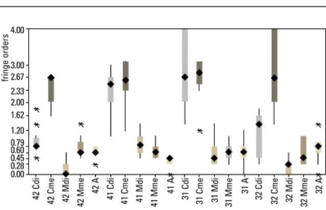
Figure 3 identifies the descriptive statistics consisting of median, first quartile and third quar-tile, maximum and minimum fringe order values resulting from the use of RUAs in the following regions: Cervicodistal (Cdi), cervicomesial (Cme), mid-distal (Mdi), mid-mesial (Mme) and apical (A) of mandibular right lateral (42), right central (41), left central (31) and left lateral (32) incisors.
Table 2 depicts the results of the Kruskal-Wal-lis and Dunn tests for fringe orders between the cervical, middle and apical regions, and between the teeth, using RUAs.
Figure 4 illustrates percentages of the major stress magnitudes related to the statistically sig-nificant differences found between root thirds, re-sulting from intrusion RUAs.
When using RUAs, the major stress magnitudes
were observed in cervical regions, with 56.6% of differences identified on the mesial and distal sur-faces and 34.8% on the distal sursur-faces, and 4.3% in the middle third of mesial surfaces and 4.3% in the apical third.
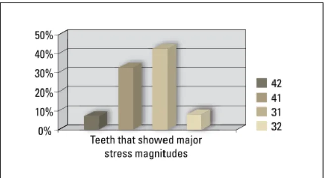
Figure 5 illustrates the percentages of the ma-jor stress magnitudes related to the statistically significant differences found between the teeth for each intrusion archwire.
By comparing fringe orders between the teeth in each root third, the major stress magnitudes were observed in central incisors, with 45.4% of the differences identified in the left central incisor and 36.4% in the right central incisor, and 9.1% in each lateral incisor.
Teeth Cdi Cme Mdi Mme Apical
Median Median Median Median Median
42 A,B0.79b A2.67a C0.0b B0.6a B,C0.6a
41 A2.5a A2.67a B0.79a B,C0.6a C0.45b
31 A2.67a A2.67a B0.45a B0.6a B0.6a
32 B1.2b A2.67a C0.28b B,C0.45a B,C0.79a
TABLE 2 - Results of Kruskal-Wallis and Dunn tests for fringe orders in the cervical, middle and apical regions using Ricketts mechanics.
Capital letters (A, B, C) differ horizontally (difference between regions in each tooth root), and lowercase letters (a, b) differ vertically (difference between teeth in each root region).
FIGURE 3 - Descriptive statistics for the fringe orders from the use of the Ricketts Base Arch.
4.00
3.00 2.67 2.33 2.00 1.62 1.20 0.79 0.60 0.45 0.28 0.00
60% 50% 40% 30% 20% 10% 0%
50%
40%
30%
20%
10%
0%
The use of gelatin appears to be quite conve-nient in research where, in addition to force distri-bution, tooth movement is also investigated, since gelatin exhibits enough creep (strain undergone by a given material over time when subjected to constant load or voltage) to accomplish tooth movement.2,7
Any comparison between the results achieved in this study and those found in the literature would be quite limited given the scarcity of stud-ies that assess intrusive mechanics using pho-toelasticity and the peculiarities inherent in the methodology.
There are reports,19 for example, on the anal-ysis of stress distribution of RUAs in the mandib-ular arch using the same wire cross-section size (0.016 x 0.022-in) and amount of force (50gf) employed in this study. However, studies differ in several aspects, among them the fact that the above study19 used stainless steel instead of chro-mium-cobalt alloy, did not use posterior anchor-age, used different photoelastic materials (gela-tin, as opposed to resin, which was used in the present study) as well as the polariscopes (plane polariscope in the aforementioned study19 vs. cir-cular polariscope in this study) and the manner in which fringes were analyzed. Although any comparison between the results can be regarded as mere speculation, the homogeneity of stresses found between the incisors in the above study19 differs from the present study, which identifi ed greater stresses in the distocervical and mid-distal surfaces of central incisors, whereas in the apical region results indicated greater stresses in lateral incisors. These results are probably related to the moment generated by the force as it dis-sipated from the distal side to the midline.
In this study, the root area of the left lateral in-cisor used in the experiment appears to be smaller than the right lateral, which might have infl u-enced stress distribution. There were, however, no signifi cant differences between the fringe orders of these teeth.
FIGURE 4 - Percentages of major stress magnitudes related to the statis-tical differences found between the apical, middle and cervical regions, mesial and distal surfaces.
FIGURE 5 - Percentage of major stress magnitudes related to statistical differences found between teeth.
dISCuSSION
Although the literature reports19 a study of fi fteen intrusion arches using the same pattern in gelatin, in this study the use of a composition of gelatin/glycerin/water was rejected after a pi-lot study was performed because when replacing the arches the integrity of the photoelastic mate-rial became gradually impaired. It was decided, therefore, that photoelastic resin would be used instead, but with an elastic modulus similar to that of gelatin, so that the light forces delivered by the intrusion arches would be capable of gen-erating internal stresses and thus be visible to photoelastic analysis.
Cervicodistal
Regions that showed major stress magnitudes
Teeth that showed major stress magnitudes
Cervicomesial Mid-distal Mid-mesial Apical
Root anatomy affects stress distribution and the key factor in determining force distribution is the apical area. Those teeth that taper from cervi-cal to apicervi-cal feature a lateral compression that in-fluences the force magnitude required to produce the same strain in cylindrical and tapered roots from apical to cervical.6
Root structure configuration and direction of force application are straightly related to stress distribution. Intrusive forces delivered along the axis induce the formation of symmetrical fringes at the apex, and tend to be more intense in teeth with smaller root areas.14
The fact that RUAs generated stresses in the apical region suggests that forces resulting from this type of arch show an axial direction. This result is consistent with a clinical18 trial that compared various intrusive mechanics and identified greater effectiveness in the intrusion of incisors with the aid of RUAs and Burstone intrusion arches.
Clinical result extrapolation should be consid-ered with caution since the photoelastic method does not accurately reproduce the role of the peri-odontal ligament.6 Natural periodontium fibers are oblique and thus prevent compression of the apex so that the distribution of axial forces is uniform along the root walls.6,10 Apparently, the tensile force in these oblique fibers induces the formation of inclined bone spicules.22 However, other authors6 argue that root form influences stimulus type. In tapered roots, pressure stimulus occurs even in the presence of axial forces while in cylindrical roots the physiological movement of intrusion can be supported by periodontal ligament fibers, which transform into tensile forces in the alveolar wall.
It has been argued that intrusive forces may be absorbed mostly by the cervical and middle areas when applied to tapered tooth roots covered with photoelastic material.8
Studies20,23 using finite element identified in the cervical region a higher stress concentration when applying intrusive forces, regardless of root form.20 Nevertheless, another study11 with finite
element found higher levels of pressure in the subapical and apical regions.
Intrusion is just one factor in the reduction of overbite using RUAs,12 as no correlation was found between amount of intrusion and reduced overbite (Kendall’s tau = 0.14), whereas correlation was found between overbite and increased lower ante-rior facial height (Kendall’s tau = 0.46) and molar extrusion (Kendall’s tau = 0.32). In the aforemen-tioned study no stabilizing segment was used in the posterior sector, so probably there was a greater extrusion of mandibular molars with a consequent increase in lower anterior facial height.
In this study a 0.021 x 0.025-in stabilizing arch was maintained in the posterior sector of all arches. Thus, the effects of the arches were more restricted to the anterior teeth.
Stresses generated by RUAs are the result not only of an intrusion activation force of 50gf, but also of an anterior lingual torque placed in the arch since the presence of anterior lingual torque also tends to increase intrusion forces.3,4,5 Moreover, the greater stresses in the mesial middle third compared to the distal middle third, found in the present study, could probably be explained5 by the fact that the presence of the wire inside the incisor brackets could displace the roots mesially. Dake and Sinclair9, in a clinical study, observed a “fan” movement in the lower inci-sors, in the group using RUAs.
It should also be stressed that the arch was built from chromium-cobalt alloy (blue Elgiloy), which features a high elasticity modulus, simi-lar to stainless steel,15 with a high load/deflec-tion ratio, thus tending to release high loads for short periods. In addition, the system of forces in RUAs is statically indeterminate, which therefore renders the calculation of acting forces and mo-ments a complex task.
The results found in this study allowed the authors to visualize and understand the effects of the use of RUAs on the lower incisors as well as identify the teeth and areas of greater stress concentration and therefore more prone to resorption. Regarding resorption, even more important than force magnitude and type is the manner in which such force is distributed around the root.8 Given the originality of this study, however, results should be viewed with caution while further investigation is warranted to confirm reproducibility. Future studies will likely contribute to an analysis of other
con-founding factors related to incisor intrusion, such as the influence of lingual torque, bracket slot angulation, wire thickness and a compari-son between different intrusive mechanics.
CONCLuSIONS
Considering the conditions under which the study was conducted, it can be concluded that:
1) Results showed that the highest stress mag-nitudes were observed in cervical regions.
Contact address
Cristiane Aparecida de Assis Claro Av. Tiradentes, 477, apto 34, Centro CEP: 12.030-180 – Taubaté/SP, Brazil E-mail: [email protected]
1. Amasyali M, Sagdiç D, Olmez H, Akin E, Karaçay S. Intrusive effects of the Connecticut intrusion arch and the utility intrusion arch. Turkish J Medical Sci. 2005;35(6):407-15. 2. Badran SA, Orr JF, Stevenson M, Burden DJ. Photo-elastic
stress analysis of initial alignment archwires. Eur J Orthod. 2003;25(2):117-25.
3. Brito AD, Isaacson RJ. Como agem os aparelhos ortodônticos. In: Bishara SE. Ortodontia. 2ª ed. São Paulo: Ed. Santos; 2004. p. 208-31.
4. Burstone CJ. Deep overbite correction by intrusion. Am J Orthod. 1977;72(1):1-22.
5. Burstone CJ. Biomechanics of deep overbite correction. Semin Orthod. 2001;7(1):26-33.
6. Campos A Júnior, Passanezi E, Nahás D, Chiapinotto GA,
Lopes ES. A fotoelasticidade em Odontologia: inluência da
base apical de sustentação. Rev Odontol Univ São Paulo. 1989;3(4):470-5.
7. Clifford PM, Orr JF, Burden DJ. The effects of increasing the reverse curve of Spee in a lower archwire examined using a dynamic photo-elastic gelatine model. Eur J Orthod. 1999;21(3):213-22.
8. Consolaro A. Reabsorções dentárias nas especialidades clínicas. 2ª ed. Maringá: Dental Press; 2005. p. 353-401. 9. Dake ML, Sinclair PM. A comparison of the Ricketts
and tweed-type arch leveling techniques. Am J Orthod Dentofacial Orthop. 1989;95(1):72-8.
10. Fantini SM. Características estáticas e dinâmicas da oclusão ideal. In: Interlandi S. Ortodontia: bases para a Iniciação. 4ª ed. São Paulo: Artes Médicas; 1999. p. 149-200.
11. Geramy A. Initial stress produced in the periodontal membrane by orthodontic loads in the presence of varying
loss of alveolar bone: a three-dimensional inite element
analysis. Eur J Orthod. 2002;24(1):21-33.
REfERENCES
12. Greig DGM. Bioprogressive therapy: overbite reduction with the lower utility arch. Br J Orthod. 1983;10:214-6.
13. Gurgel JA, Ramos AL, Kerr SD. Fios ortodônticos. Rev Dental Press Ortod Ortop Facial. 2001;6(4):103-14. 14. Hayashi RK, Chaconas SJ, Caputo AA. Effects of force
direction on supporting bone during tooth movement. J Am Dent Assoc. 1975;90(5):1012-7.
15. Kapila S, Sachdeva R. Mechanical properties and clinical applications of orthodontic wires. Am J Orthod Dentofacial Orthop. 1989;96(2):100-19.
16. Langlade M. Terapêutica ortodôntica. 1ª ed. São Paulo: Ed.
Santos; 1993. p. 122-46.
17. McNamara JA, Brudon WL. Orthodontics and dentofacial Orthopedics. Ann Arbor: Needham; 2001.
18. Melsen B, Agerbaek N, Markenstam G. Intrusion of incisors in adult patients with marginal bone loss. Am J Orthod Dentofacial Orthop. 1989;96(3):232-41.
19. Mota LM. Estudo fotoelástico da intrusão de dentes anteriores na técnica do arco segmentado [dissertação]. Campinas (SP): Centro de Pesquisas Odontológicas São Leopoldo Mandic; 2005.
20. Oyama K, Motoyoshi M, Hirabayashi M, Hosoi K, Shimizu N. Effects of root morphology on stress distribution at the root apex. Eur J Orthod. 2007;29(2):113-7.
21. Ricketts R. Bioprogressive therapy as an answer to orthodontic needs. Part II. Am J Orthod. 1976;70(4):241-68. 22. Reitan K, Rygh P. Princípios e reações biomecânicas. In: Graber TM, Vanarsdall RL Jr. Ortodontia: princípios e técnicas atuais. 2ª ed. Rio de Janeiro: Guanabara Koogan; 1996. p. 88-174. 23. Wilson AN, Middleton J, Jones ML, McGuinness NJ. The
inite element analysis of stress in the periodontal ligament
when subject to vertical orthodontic forces. Br J Orthod. 1994;21(2):161-7.
Submitted: May 7, 2008