Abstract
The present paper is concerned with the analysis of the effect of the loading rate in a particular class of single lap joints used in the oil industry. The adhesive/adherend system consists of ASTM A36 steel plates bonded with an epoxy/ceramic composite. The loading rate sensitivity is analysed considering two different situa-tions: (i) strain controlled quasi-static rupture tests and (ii) appli-cations in which the joint may oscillate like a spring. This second situation is motivated by a specific application: the transport of an ethanol reservoir by a crane using a special truss lifting system attached to the tank through bonded joints. Quasi-static tensile tests allow observing a rate-dependent behaviour of the joint with higher strengths for higher cross-head velocities. An algebraic equation is proposed to predict the dependence of the rupture force on the elongation rate in tensile tests and the model predictions are in good agreement with experimental results. However, in the case of the transport of a tank with mass M (situation (ii)), the lifting system cannot be only designed to resist the static load (the weight). Fast loading may induce vibration. Like in a spring-mass system, even a very small oscillation of the joint induces a dynam-ic load that is higher than the statdynam-ic load. A simple analysis allows proposing conditions for a safe operation in this case.
Keywords
Bonded joints; Epoxy/ceramics composites, Quasi-brittle behav-iour; Rate-dependency; Vibration
Load Rate Effects in Adhesive Single Lap Joints
Bonded with Epoxy/Ceramic Composites
1 INTRODUCTION
Some specific materials and composite structures present a quasi-brittle behaviour. In a monotonic tensile test, the elastic properties are statistically rate-insensitive, the inelastic deformation is almost negligible, but the rupture force is rate-dependent (Costa Mattos et al. (1992), Costa Mattos and
Heraldo da Costa Mattos a Luiz Carlos da Silva Nunes a Antonio Henrique Monteiro a,b a Universidade Federal Fluminense,
Graduate Program in Mechanical Engineering,Laboratory of Theoretical and Applied Mechanics (LMTA), 24210-240 Niterói, RJ, Brazil
[email protected] [email protected]
bPETROBRAS - Petróleo Brasileiro
S.A., Research Center CENPES), 21941-915 Cidade Universitária - Ilha do Fundão, Rio de Janeiro, RJ, Brazil [email protected]
http://dx.doi.org/10.1590/1679-78252818
Sampaio (1995), Bazant and Planas (1997), Gary and Bailly (1998), da Costa Mattos et al. (2009), Nunes et al. (2011), Reis et al. (2013), Reis et al. (2014), Gesualdo and Monaco (2015), Xenos et al. (2015), for instance). In the case of bonded joints, commercial adhesives may range from brittle to ductile (Fernandes et al., 2015) and the basic requirement is that each one must possess adequate mechanical properties for a specific application.
The present work is concerned with the analysis of load rate effects in quasi-brittle adhesive single lap joints bonded with epoxy/ceramic composites. The use of bonded joints with quasi-brittle behaviour is not new, but still a very active area of research (Pelissou and Lebon (2009), Giuliese et al. (2013, 2015), Leuschner et al. (2015), Gang Li and Chun li (2015)). However, there are few ex-perimental investigations on the structural rate-dependent behaviour of this kind of joint (Essersi et al., 2009), since most of the studies concerned with the rate-dependency analysis considers joints with inelastic behaviour. In these cases, the rate-dependent behaviour is viscoelastic or elasto-viscoplastic, and the papers are generally focused on new adhesives for the automobile and aero-nautics industries (such as rubber nanocomposites), on impact loading, and on the joint cyclic ine-lastic behaviour and long-term behaviour (ratcheting, shakedown and fatigue, creep and ageing: da Costa Mattos and Martins (2013), Yang et al. (2015), Chowdhuri and Xia (2013), Reis et al. (2015) , for instance).
This paper is the continuation of a series of studies on the failure analysis of quasi-brittle adhe-sive joints using a global approach (Costa-Mattos et al., 2010, da Costa Mattos et al., 2011, 2012a, 2012b, 2013). The analysis is valid for general adhesives with quasi-brittle behaviour and highly resistant adherends but the adhesive/adherend system consists of ASTM A36 steel plates bonded with an epoxy/ceramic composite often used in oil industry for the repair and protection of metal surfaces that is also being used as adhesive in some applications in strongly corrosive environments. Although the analysis can be performed using more complex approaches (a more detailed numerical analysis, either based on multiscale models, continuum damage models, cohesive zone models or on the extended finite element method (Kulkarni et al., 2010, and Fernandes et al., 2015, for instance), the idea is to present simple procedures for designers to decide if a given loading rate is more con-venient or not for a given engineering application. These simplified procedures would allow a pre-liminary integrity analysis before a more expensive and time-consuming numerical simulation.
Quasi-static tensile tests were performed using different cross-head velocities. Statistical analysis shows that the velocity has indeed an effect on joint resistance. A simple equation is proposed to predict the dependence of the rupture force on the elongation rate (assumed to coincide with the cross-head velocity) of the joint in tensile tests and the model predictions are in good agreement with experimental results.
geometries using a shape factor. Using this shape factor, a preliminary estimate of the necessary bonded area for an arbitrary problem can be made from simple rupture test in standard joints.
The present study is concerned with including the effect of the loading rate in the simplified methodology proposed in da Costa Mattos et al. (2012a). Two kinds of effects are accounted: the structural rate-dependency and the oscillatory movements. Knowing adhesive properties is funda-mental for and adequate design of the bonded joints. However, the lifting system cannot be de-signed only to resist the static load (the weight of the tank). In the present paper, this is shown through a very simple vibration analysis where the lift system is modelled as a quasi-brittle spring and the tank as a concentrated mass. The analysis shows that even a very small oscillation of the system induces a dynamic force that is much higher than the static load (like in a spring-mass sys-tem). These oscillations depend on different factors, but, in many cases, cannot be avoided. It is shown that even a constant lifting velocity may induce a vibration that can lead the system to fail-ure.
A second order ordinary differential equation relates the crane movement with the system vi-bration (joints and truss lifting system). This equation, combined with the expression proposed to model the dependence of the joint rupture force on the elongation rate, allows the definition of con-ditions for a safe operation in the dynamic case (connecting crane operating speed, mass of the tank and rate-dependent strength of the bonded joint). An illustrative example of how this methodology may be used by designers for a preliminary estimate of the necessary glued area for a given ad-herend/adhesive system is also presented and analysed.
2 MATERIALS AND METHODS
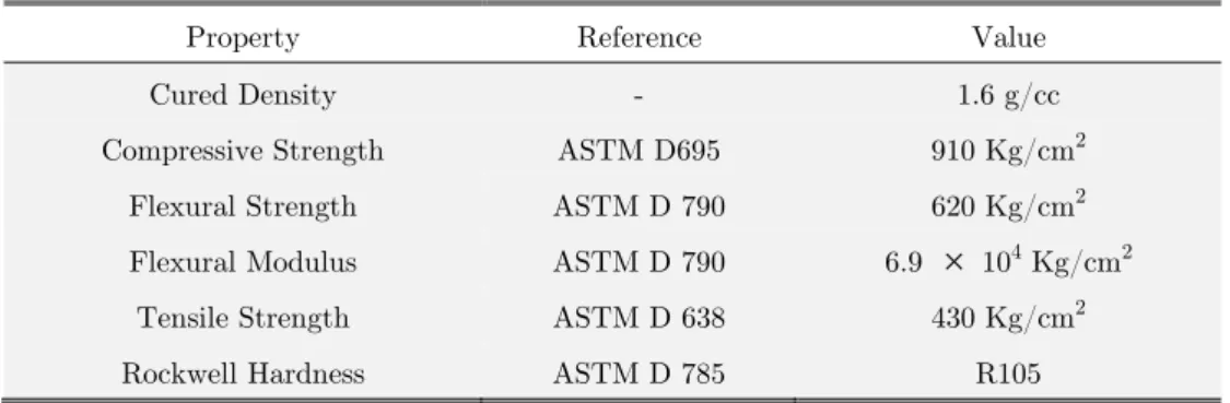
In the present study, the adhesive/adherend system consists of SAE 1020 steel plates (with Young’s modulus 170 GPa, yield stress 210 MPa, ultimate strength 380 MPa and Poisson´s ratio 0.3) bonded with a commercial epoxy/ceramic composite: a mixture of ceramic particles and a two com-ponent, crystallization resistant, modified epoxy resin structure reacted with an aliphatic curing agent). Further technical data about this composite is presented in Table 1.
Property Reference Value
Cured Density - 1.6 g/cc
Compressive Strength ASTM D695 910 Kg/cm2
Flexural Strength ASTM D 790 620 Kg/cm2
Flexural Modulus ASTM D 790 6.9
104 Kg/cm2Tensile Strength ASTM D 638 430 Kg/cm2
Rockwell Hardness ASTM D 785 R105
Table 1: Adhesive properties.
mechanical but also to chemical treatment. The mechanical treatment consisted of surface grit blasting, producing an average roughness parameter Rt between 81 and 104 μm. This roughness level is a recommendation made by the manufacturer to the use of the epoxy/ceramic composite as adhesive. Chemical treatment consisted on surface spraying silanisation. Bonding was performed under controlled conditions (25°C and 50% R.U.) and followed by a curing process for 24h at 40°C.
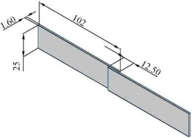
Figure 1: Specimen geometry.
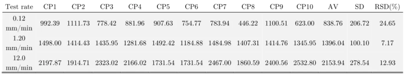
To check the influence of the cross-head velocity on the rupture force, initially tests were per-formed at three elongation rates: 0.12 mm/min, 1.2 mm/min and 12.0 mm/min (10 specimens for each loading rate). After these tests, a new batch of adhesives (ageing is also important in this case) was used to perform new tests at five different rates 0.12 mm/min, 0.6 mm/min, 1.2 mm/min, 6.0 mm/min, 9 mm/min and 12.0 mm/min.
3 RESULTS AND DISCUSSION
3.1 Quasi Static Tensile Tests
Test rate CP1 CP2 CP3 CP4 CP5 CP6 CP7 CP8 CP9 CP10 AV SD RSD(%) 0.12
mm/min 992.39 1111.73 778.42 881.96 907.63 754.77 783.94 446.22 1100.51 623.00 838.76 206.72 24.65 1.20
mm/min 1498.00 1414.43 1435.95 1281.68 1492.42 1184.88 1484.98 1407.31 1414.76 1345.95 1396.04 100.10 7.17 12.0
mm/min 2197.87 1914.71 2323.02 2166.02 1731.54 1731.54 2467.00 1860.59 2400.56 2532.80 2153.94 278.54 12.93
Table 2: Rupture force for different cross-head velocities (N).
Figure 2: Tensile tests with different cross-head velocities. Quasi-brittle behaviour.
After these tests, a new batch of joints was used to perform new tests at five different rates. Ageing is important in this case since the properties of the non-cured epoxy/ceramic composite change in contact with air. The new joints properties correspond to the same (non-cured) adhesive aged after a few weeks. Table 3 present the average rupture force for the joints considering different elongation rates.
Elongation rate (mm/min) average rupture Force (N)
0.12 2539.2
0.6 2994.0
1.2 3193.3
6.0 3413.7
9.0 3963.0
12.0 4070.82
Table 3: Mean rupture forces for different tests velocities.
[(1 exp(
)]
r o
F
=
F
+
a
-
-
b
d
(1)o
F
, a andb
are material constants (see Fig.3). From eq. (1) it is simple to verify thatmax
( )
F
rlim( )
F
r(
F
oa
)
d
=
=
+
¥
and0
r
dF
ab
d
d d
=
=
(2)Figure 3: Rupture force. Definition of the constants Fo, a and b.
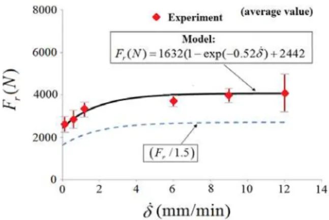
Table 4 presents the material constants identified experimentally for this class of joints and Fig. 4 shows the comparison between predicted and experimental rupture forces for different elongation rates. Despite the scatter of the experimental results, the use of expression (1) and a safety factor of 1.5 is enough for a safe prediction. It is interesting to remark that the mean rupture force varies significantly from
F
o= 2242 N to(
F
o+
a
)
= 4074 N. The maximum mean rupture force is 1.67(obtained using higher loading velocities) of the minimum one.
Fo(N) a(N) b(min/mm)
2442 1632 0.52
Table 4: Joint parameters.
3.2 Vibration Induced by the Loading Process
In some particular situations, the mechanical system may behave like a spring-mass system. In this case, even a very small oscillation of the joint induces a dynamic load, which can be higher than the static load. The motivation for this analysis is a practical problem that has already been analyzed in da Costa Mattos et al. (2012a): the transport of an ethanol reservoir by a crane using a special truss lifting system attached to the tank through bonded joints as shown in Fig. 5. Fast loading may induce vibration and the lifting system cannot be only designed to resist the static load.
Figure 5: Transport of an ethanol reservoir by a crane using a special truss lifting system attached to the tank through bonded joints.
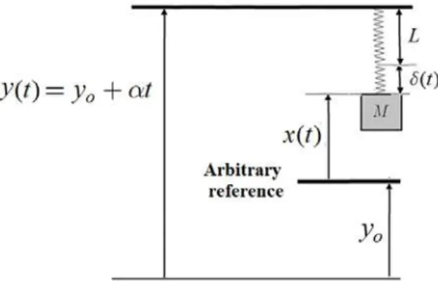
In order to perform a simplified analysis, the joints and truss lifting system is treated as a qua-si-brittle spring (constant stiffness but the rupture depends on rate of elongation. Damping is negli-gible). Therefore, the problem is reduced to an undamped vibration analysis (Figs. 6 and 7).
L
is the length of the undeformed spring.M
is the mass of the tank andK
the stiffness of the spring.g
is the acceleration of gravity. Only a vertical displacementy
=
y
o+
a
t
from the ground is takeninto account.
x t
( )
is the position of the tank from an arbitrary fixed referencey
o. This expressionwas chosen to eliminate any acceleration of the crane movement (
y
=
0
). The goal is to show that vibration is induced even in this case, that the force acting on the spring is different from the ob-tained in the equilibrium problem, and that this force depends directly on the velocitya
.Figure 7: Problem modelled as a spring-mass system.
The basic equation governing of this problem is very simple (
d
=
(
a
t
- -
x
L
)
is the spring elongation)(
)
Mx
= -
Mg
+
K
a
t
- -
x
L
(3)The solution of this initial value problem formed by eq. (3) and the following arbitrary condi-tions
x t
(
=
0)
=
x
oandx t
(
=
0)
=
x
ois( )
a
sin( )
b
cos( )
Mg
x t
t
wt
wt
L
w
w
K
a
é
ù
=
-
ê
+
+
+
ú
ê
ú
ë
û
(4)with
K
w
M
=
, oMg
b
w x
L
K
é
ù
= -
ê
+
+
ú
ê
ú
ë
û
,a
= -
a
x
o (5)w
is the characteristic (or natural) angular frequency of the system. The forceF t
( )
acting on the spring (joints and truss lifting system) is( )
(
)
a
sin( )
b
cos( )
F t
K
t
x
L
K
wt
wt
Mg
w
w
a
æ
ç
ö÷
=
- -
=
ç
çè
+
÷
÷
ø
+
(6)From eq. (6), it is clear that the maximum dynamic force can be higher than the static force
Mg
provideda
¹
0
orb
¹
0
.3.2.1 Particular Choices of Initial Conditions
The behaviour of the spring-mass system is strongly dependent of the initial conditions. In this sec-tion, a few examples are presented to show that small perturbations can strongly affect the force acting on the system. Three different initial conditions are analysed.
o
Mg
x
L
K
é
ù
= -
ê
+
ú
ê
ú
ë
û
andx
o=
a
(7)In this particular case, the tank is initially in equilibrium (the static elongation is (
Mg
/
K
) = 2/
g w
, see Fig. 8) and is lifted from the reference point with the positionx t
( )
given by the follow-ing expression( )
Mg
x t
L
t
K
a
é
ù
= -
ê
+
ú
+
ê
ú
ë
û
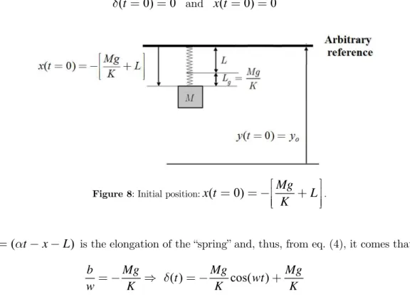
(8)Any other set of initial conditions implies an oscillatory movement of the system. An alternative set of initial conditions is to assume that the spring is initially undeformed and the rate
x
is zero (this is probably the most common initial condition).(
t
0) 0
d
=
=
andx t
(
=
0) 0
=
(9)Figure 8: Initial position:
x t
(
0)
Mg
L
K
é
ù
=
= -
ê
+
ú
ê
ú
ë
û
.(
t
x
L
)
d
=
a
- -
is the elongation of the “spring” and, thus, from eq. (4), it comes that( )
cos( )
b
Mg
Mg
Mg
t
wt
w
= -
K
d
= -
K
+
K
(10)Therefore, the maximum elongation
d
maxismax
2
Mg
K
d
=
(11)and the maximum force
F
maxis twice the static (equilibrium) force stMg
F
K
=
max max
2
2
stMg
F
K
F
K
d
As it can be verified, due to the oscillatory movement, the maximum dynamic load is twice the static load, independently of the stiffness of the system and of the lifting velocity
a
.In a second example, the system is in equilibrium and a perturbation is induced by the lifting velocity:
x t
(
=
0)
=
a
.(
0)
Mg
x t
L
K
é
ù
=
= -
ê
ê
+
ú
ú
ë
û
,x t
(
=
0)
=
a
(13)From eq. (4), it is possible to verify that the solution of this initial value problem is
( )
sin( )
Mg
x t
t
wt
L
w
K
a
a
é
ù
=
-
ê
+
+
ú
ê
ú
ë
û
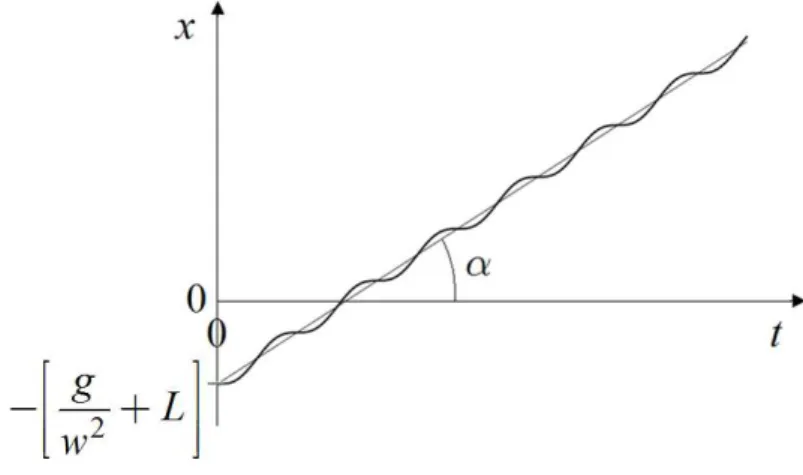
(14)Fig. 9 presents the evolution of the variable
x
in this case. The spring elongationd
ismax
sin( )
Mg
Mg
t
x
L
wt
w
K
w
K
a
a
d
=
a
- - =
+
d
=
+
(15)and the force
F t
( )
acting on the spring (joints and truss lifting system) ismax
( )
sin( )
F t
=
K
d
=
a
KM
wt
+
Mg
F
=
a
KM
+
Mg
(16)Figure 9: Oscillatory evolution of the position
x
.In this case, the maximum intensity will depend on the stiffness of the system and on the lift velocity
a
. It is interesting to observe that higher forces are obtained (for a fixed massM
) for higher values of the stiffness.maximum dynamic force is higher than the static one and the difference is more important for high-er lifting velocities
a
.3.2.2 Transport of Cylindrical Reservoirs for Ethanol Storage - An Illustrative Example Accounting Oscillatory
Movements
In this section, it is shown how this methodology can be used by designers as a preliminary estimate of the adequate adhesive area in the transport of ethanol storage tanks. In [26] a simple methodolo-gy was proposed to define the necessary bonded area for an arbitrary static load for a joint with quasi-brittle behaviour under quasi-static conditions. The rupture force
F
maxfor an arbitrary jointwith quasi-brittle behaviour can be estimated from the rupture force
F
maxref of a reference joint (such as a the single lap joint depicted in Fig. 1) by correcting it through a shape factorh
that accounts for geometric effects.h
=
max max
ref
F
F
withref ref
W L
W
L
h
=
(17)W
is the overlap width andL
the overlap length. An ASTM single lap joint (W
=
25 mm andL
=
12.5 mm, Fig. 1) with the same surface preparation that would be adopted in the field can be used as the Reference Joint. For a conservative analysis, it is suggested to considerF
maxref the minimum value ofF
r in eq. (1): maxref =o
F F . Due to the scatter of the results (see Fig. 4), it is also
suggested use a safety factor
V
higher that 1.5.h
V
³
max o
F
F
withref ref
W L
W
L
h
=
(18)The dynamic nature of the problem is accounted in the methodology simply by correcting the static loading. In the case of a oscillatory movement, if the first set of boundary conditions analysed in the previous section is considered (load initially at rest and spring not in tension), the maximum load acting on the system is equal to
2
Mg
, independently of the stiffness of the lifting system.In order to have a reasonable balance during transportation, the lifting system is fixed in the tank trough n joints distributed around the external surface of the tank. The maximum tensile load acting on each joint is obtained dividing the total maximum load by the number of joints.
Taking
F
max=
(2
Mg
/ )
n
, maxref = oF F = 2442N,
W
ref=25 mm,L
ref =12.5 mm, it resultsfrom eq. (18) that
V
V
=
æ
ç
ç
ç
ö÷
÷
÷
=
÷÷
çè
ø
max max2
ref ref ref o ref refW L
Mg
F
F
W
L
W L
n
F
W
L
(19)V
æ ö÷
ç ÷
ç ÷÷
çè ø
18821.43
=
W L
n
(20)Therefore, the geometry of the joint area (values of the overlap width
W
and of the overlap lengthL
) can be computed using eq. (20) and assuming a fixed relationa
betweenW
andL
(W
=
l
L
) as followsif
V
l
l
æ
ö÷
ç
=
ç
÷
÷÷
=
çè
ø
0.67
18821.43
,
L
W
L
n
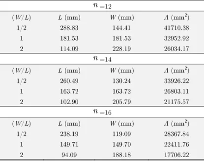
(21)Table 5 shows the computed values of
W
andL
using a safety factor V = 1.5for different rates(
W
/ )
L
. As it can be verified, joints withW
>
L
tends to have a higher strength (and, consequently, they require a smaller bonding area). For practical purposes [26] it is suggested the following empirical relations for such kind of preliminary study: (i)0.5
£
(
W
/ )
L
£
2.0
and (ii)max{ , }
W L
£
200
mm
.n
=12(W/L) L (mm) W (mm) A (mm2)
1/2 288.83 144.41 41710.38
1 181.53 181.53 32952.92
2 114.09 228.19 26034.17
n
=14(W/L) L (mm) W (mm) A (mm2)
1/2 260.49 130.24 33926.22
1 163.72 163.72 26803.11
2 102.90 205.79 21175.57
n
=16(W/L) L (mm) W (mm) A (mm2)
1/2 238.19 119.09 28367.84
1 149.71 149.70 22411.76
2 94.09 188.18 17706.22
Table 5: Predicted necessary glued area for each joint.
4 CONCLUSIONS
higher for higher loading rates in tensile tests (ranging from a minimum rupture force
F
oto amax-imum
F
rmax»
1.67
F
o - above a certain velocity level, this effect is negligible and the joint becamerate-insensitive), attention must be taken in some real problems due to the dynamic nature of the problem.
The current investigation showed that in specific applications, such as the transport of an etha-nol reservoir by a crane using a special truss lifting system attached to the tank through bonded joints, the problem behaves like a spring-mass system and oscillations induce higher forces on the joints what can lead to unexpected failures or affect the crane stability. It was not the goal to per-form a precise vibration analysis of the system, but to show that even in a situation with very small oscillation amplitude, the maximum tensile force applied on the joint is higher than the static load.
The purpose of this work was also to provide a method to easily perform the failure analysis of a class of single-bonded lap-joints with arbitrary glued area. A simple procedure to design the ade-quate bonded area is proposed, extending the study proposed in da Costa Mattos et al. (2012a) in the case of static loading. In such a procedure, it only necessary to perform tests using standard ASTM joints (a minimum of 3 tests with different loading rates). Due to the huge variation of the strength when the joint is prepared in the field, a shape factor may be used to obtain a preliminary estimate of the adhesive area (always brittle-elastic adhesives) before a more adequate (but com-plex) finite element computation.
References
Bazant, Z.P., Planas, J., editors (1997). Fracture and Size Effect in Concrete and Other Quasibrit-tle Materials. CRC Press.
Chowdhuri, M.A.K., Xia Z. (2013). Interface bonding strength measurement of a joint between elastic and viscoelastic materials. Composites Part B: Engineering 44:253-259.
Costa Mattos, H., Fremond, M., Mamiya. E.N. (1992). A simple model of the mechanical behavior of ceramic-like materials. International Journal for Solids and Structures 29:3185-3200.
Costa Mattos, H.S., Sampaio, R. (1995). Analysis of the Fracture of Brittle Elastic Materials Using a Continuum Damage Model. Structural Engineering and Mechanics 3:411 – 427.
Costa-Mattos, H.S., Monteiro, A.H., Sampaio, E.M. (2010). Modelling the strength of bonded butt-joints. Composites Part B: Engineering 41:654–662.
da Costa Mattos H.S., Sampaio, E.M., Monteiro, A.H.(2013). Static failure analysis of adhesive corner joints. International Journal of Adhesion and Adhesives 47:110–116.
da Costa Mattos, H.S., Domingues, M.P., Rochinha, F.A. (2009). Structural failure prediction of quasi-brittle structures: modeling and simulation. Computational Materials Science 46 :407 – 417. da Costa Mattos, H.S., Monteiro, A.H., Palazzetti, R. (2012). Failure analysis of adhesively bonded joints in composite materials", Com A.H. Monteiroe R. Palazzetti. Materials and Design 33: 242-247.
da Costa Mattos, H.S., Sampaio, E.M., Monteiro, A.H. (2012). A simple methodology for the design of metallic lap joints bonded with epoxy/ceramic composites. Composites Part B: Engineering 43:1964–1969.
da Costa Mattos, H.S., Martins, A.S. (2013). Plastic behaviour of an epoxy polymer under cyclic tension. Polymer Testing 32:1-8.
Essersi, O, Tarfaoui, M., Boyd, S.W., Meraghni, F., Shenoi, R.A. (2009). Dynamic study of adhe-sively bonded double lap composite joints. In, 17th International Conference on Composite Materi-als (ICCM-17),Edinburgh, UK, p. 27 - 31.
Fernandes, T.A.B., Campilho, R.D.S.G, Banea, M.D., da Silva L.M.F. (2015). Adhesive selection for single lap bonded joints: experimentation and advanced techniques for strength prediction. The Journal of Adhesion 91:841-862.
Gang Li, Chun Li. (2015). Assessment of debond simulation and cohesive zone length in a bonded composite joint. Composites Part B: Engineering 69:359–368.
Gary G, Bailly, P. (1998).Behaviour of quasi-brittle material at high strain rate. Experiment and modelling. European Journal of Mechanics - A/Solids 17:403–420.
Gesualdo, A., Monaco, M. (2015). Constitutive behaviour of quasi-brittle materials with anisotropic friction. Latin American Journal of Solids and Structures 12:695-710.
Giuliese, G., Palazzetti, R., Moroni, F., Zucchelli, A., Pirondi, A. (2013) A numerical investigation on the interlaminar strength of nanomodified composite interfaces. Composites Part B: Engineering 55:635-641.
Giuliese, G., Palazzetti, R., Moroni, F., Zucchelli, A., Pirondi, A. (2015). Cohesive zone modelling of delamination response of a composite laminate with interleaved nylon 6,6 nanofibres. Composites Part B: Engineering 78:384-392.
Kulkarni, M.G., Matouˇs, K., Geubelle, P.H. (2010). Coupled multi-scale cohesive modeling of fail-ure in heterogeneous adhesives. International Journal for Numerical Methods in Engineering 84:916– 946.
Leuschner, M., Fritzen, F., van Dommelen, J.A.W., Hoefnagels, J.P.M. (2015). Potential-based constitutive models for cohesive interfaces: Theory, implementation and examples. Composites Part B: Engineering 68:38–50.
Nunes, L.C.S., Reis, J.M.L., da Costa Mattos, H.S. (2011). Parameters identification of polymer concrete using a fracture mechanics test method and full-field measurements. Engineering Fracture Mechanics 78:2957-2965.
Pelissou, C., Lebon, F. (2009). Asymptotic modeling of quasi-brittle interfaces. Computers and Structures 7:1216–1223.
Reis, J.M.L, Amorim, F.C., da Silva, A.H.M.F.T., da Costa Mattos, H.S. (2015). Influence of tem-perature on the behavior of DGEBA (bisphenol A diglycidyl ether) epoxy adhesive. International Journal of Adhesion and Adhesives 58:88-92.
Reis, J.M.L., Coelho, J.V.L., da Costa Mattos, H.S. (2013). A continuum damage model for glass/epoxy laminates in tension. Composites Part B: Engineering 52:114-119.
Xenos, D., Grégoire, D., Morel, S., Grassl, P. (2015). Calibration of nonlocal models for tensile frac-ture in quasi-brittle heterogeneous materials. Journal of the Mechanics and Physics of Solids 82:48– 60.