SHAPE CONTROL OF LAMINATED PANELS USING
PIEZOELECTRIC ACTUATORS
José M. Simões Moita1*, Cristóvão M. Mota Soares2, Carlos A. Mota Soares2 and José Herskovits3
1:Escola Superior de Tecnologia Universidade do Algarve Campus da Penha, Faro, Portugal.
2:Departamento de Engenharia Mecânica Instituto Superior Técnico
Universidade Tecnica de Lisboa
Av Rovisco Pais, 1049-001, Lisboa Codex, Portugal.
[email protected],[email protected]
3:COPPE/UFRJ
Universidade Federal do Rio de Janeiro
Caixa Postal 68503, 21945-970, Rio de Janeiro, Brazil.
Keywords: Finite Elements, Piezoelectric Actuators, Optimization.
Abstract. This paper presents a finite element formulation based on the classical laminated
plate theory for laminated structures with integrated piezoelectric layers or patches, acting as actuators. The finite element model is a single layer triangular nonconforming plate/shell element with 18 degrees of freedom for the generalized displacements, and one electrical potential degree of freedom for each piezoelectric element layer or patch. An optimization of the electric potential distribution is performed, in order to reach the specified structure transverse displacement distribution, minimizing an error function (shape control). A gradient based algorithm is used for this purpose. Results are presented and discussed.
1. INTRODUCTION
Composite structures incorporating piezoelectric sensors and actuators are increasingly becoming important due to the offer of potential benefits in a wide range of engineering applications such as vibration and noise suppression, shape control and precision positioning. The optimal location of the piezoelectric patches, in order to maximize the piezoelectric actuators efficiency, is one of the tasks to be considered in the analysis of the piezolaminated structures.
A significant number of works in the fields of analysis, control and optimization in composite structures integrating piezoelectric material had been carried out. One of the pioneering works is due to Allik and Hughes [1] who carried out the variational formulation and developed a solid finite element for vibration analysis. Tzou and Tseng [2] presented a finite element formulation for plates and shells containing integrated distributed piezoelectric sensors and actuators applied to control advanced structures. In more recent works Chen et al. [3] developed a finite element based on the first order displacement field for dynamic analysis of plates where the vibration active control is obtained with the actuators potential been given by an amplified signal of the sensors potential which arises an active damped system, and Samanta et al. [4] developed an eight-nodded finite element for the active vibration control of laminated plates with piezoelectric layers acting as distributed sensors and actuators. The active control capability is studied using a simple algorithm with negative velocity feedback. Also Lam et al. [5] and Moita et al. [6] developed finite element models based on the classical laminated theory and higher order shear deformation theory, respectively, for the active control of composite plates containing piezoelectric sensors and actuators using the Newmark method, Bathe [7], to calculate the dynamic response of laminated structures. Active vibration control is obtained through actuators potential, which is given by an amplified signal of the sensors potential. Most of past work in the area of adaptive structures has focused on the analysis of structures with sensors and actuators, and the corresponding associate control system.
Very few works have focused on the development of methodologies for the optimization of laminated structures incorporating sensors and actuators, to enhance their performance. A model for the optimization of the induced-strain actuator location and configuration for active vibration control had been proposed by Liang et al. [8]. Batra and Liang [9] used a three-dimensional linear theory of elasticity to find the optimal location of an actuator on a simple-supported rectangular laminated plate with embedded PZT layers. The optimal design is obtained by fixing the applied voltage and the size of the actuator and moving it around in order to find the maximum out-of-plane displacement. More recently, Franco Correia et al. [10] presented refined finite element models based on higher order displacement fields applied to the optimal design of laminated composite plates with embedded or surface bonded piezoelectric actuators and sensors, and Achuthan et al. [11] study the shape control of composite laminated beams with nonlinear piezoelectric patch actuators developing a finite element model.
In the present work a discrete model based on the classical laminated plate theory is developed. A three-nodded flat triangular finite element is used, with 18 mechanical degrees of freedom
and one electric degree of freedom per piezoelectric layer or patch of the finite element. The optimal electric potential distribution to perform the structure shape control is carried out using a gradient-based algorithm methodology, in association with algorithm FAIPA, Herskovits et al. [12]. The model is applied in the optimization of illustrative laminated plate cases, and the results are presented and discussed.
2. PIEZOELECTRIC LAMINATES. CONSTITUTIVE EQUATIONS.
Assuming that a piezoelectric composite plate consists of several layers, including the piezoelectric layers, the constitutive equation for an orthotropic layer of the laminate substrate, is
ε
σ=Q (1)
and the constitutive equations of a deformable piezoelectric material, coupling the elastic and the electric fields are given by, Tiersten [13]
E e Qε σ= − (2) E p e D= T ε + (3)
where σ=
[
σxx σyy σxy]
Tis the elastic stress vector and[
]
T xy yy xx
= ε ε γ
ε the elastic strain
vector, which components are associated with the displacement field of the classical laminated plate theory, Q the elastic constitutive matrix, e the piezoelectric stress coefficients matrix,
[
]
T z y x E E E =E the electric field vector, D=
[
Dx Dy Dz]
T the electric displacement vector and p the dielectric matrix, in the element local system (x,y,z) of the laminate.Qij,eij,pij are functions of ply angle α for the kth layer, and are given explicitly in Reddy [14].The electric field vector is the negative gradient of the electric potentialφ, which is assumed to be applied in the thickness t direction, where it can vary linearly, i.e. k
φ −∇ = E ; E=
{
0 0 Ez}
T (4) where k z /t E =−φ (5)The constitutive equations (2) and (3) can be written in the form
ε ε σ ˆ ˆ E p -e e Q D σ ˆ T =C − = = (6)
The flat triangular finite element model has three nodes and six degrees of freedom per node, the displacements u0, v0, w0 and rotations θx,θy,θz. The introduction of fictitious stiffness coefficients Kθz,corresponding to rotationsθz, to eliminate the problem of a singular stiffness matrix, for which the elements are coplanar or near coplanar, is required. The element local displacements, slopes and rotations are expressed in terms of nodal variables through shape functions N given in terms of area co-ordinates, Zienckiewiczi [15]. The displacement field can be represented in matrix form as:
a N Z d N Z u= ( i)= 3 1 = i i
∑
; d= N di =Na 3 1 = i i∑
(7) with{
}
T zi yi xi i 0 i 0 i 0 i = u v w θ ,θ ,θ d ; a={
d1 d2 d3}
T (8) − = 0 0 0 1 0 0 0 0 0 1 0 0 0 0 0 1 z z Z (9)and the strain field as follows
{ } {
z}
(
z)
di mb a 3 1 i b i m i b m B B =B + = ε + ε = ε∑
= (10)The electric field is given by
φ −
= Bφ
E (11)
where Bφ is the electric field – potential relations matrix given by
= φ NPL 1 1/t 0 0 1/t L M O M L B (12)
From the virtual work principle, we obtain the static equations of a laminated composite plate:
0 dS dS dV dA dz ˆ Cˆ ˆ S i i i S N 1 = K A V h h e L t k T e k 1 -k − δ + δ + δ + δφ = δ ∫ ∑ ∫ ∑ ∫ ∫ ε ε ∫f u T u F u Q (13)
{ }
a dV{ }
a dS{ }
a{ }
dS 0 dA dz a 0 0 0 0 a S S c T V T N 1 K A mb T T mb T h h T T T k 1 -k = φ δ + δ + δ + δ + − φ − φ δ ∫ ∫ ∫ ∑ ∫ ∫ = φ φ Q F T N f N p e e Q B B B B (14)To the first term of Eq. (13), corresponds the element stiffness, which is defined by:
∑ ∫ ∫ − = = φ φ φφ φ φ N 1 = K A h h mb k T T mb u u uu k 1 -k dA dz 0 0 0 0 K K K K B B B B p e e Q K (15)
To the second term of Eq. (13), corresponds the external mechanical force vector Fextmec and the applied electric charge vector Fele.
The element stiffness matrix as well as external load vector are initially computed in the local coordinate system attached to the element. To solve general structures, local - global transformations are needed, Zienckiewicz [15]. After these transformations the assembled system of equations for laminated structures with integrated piezoelectric layers or patches, acting as actuators, is:
= φ φφ φ φ ele mec ext u u uu F F K K K K q (16)
This system of equations can be written in the following form:
[
Kuu]{ }
q ={
Fextmec −Kuφφ}
(17)[ ]
Kφu{ }
q +[ ]
Kφφ{ }
φ ={ }
Fele (18) In practice, voltage is specified as input to the actuators, and we than write:[ ]{ }
K q{
Fmec F( )A}
ext
uu = − (19)
where
{ }
F( )A ={
-Kuφφ}
is an additional force due to the voltage applied to the actuators.4. OPTIMAL DESIGN
A general structural optimization problem can be stated as
{
Ω(b)}
min subject to:
n ,..., 1 i b b bli ≤ i ≤ iu = m ,..., 1 j 0 ) , ( j ≤ = Ψ q b (20)
where Ω(b) is the objective function, b is the vector of design variables b , i Ψj(q,b) are the
m inequality behavioural constraint equations, b and li b are respectively, the lower and upper iu limits of the design variables and n is the total number of design variables.
In this work, the constraint normalized effective stress of Tsai-Hill is considered:
ψ−1≤0 with σ σ σ − σ σ + σ σ + σ σ = ψ 2 U 11 22 11 2 U 12 12 2 U 22 22 2 U 11 11 (21)
If the objective function and/or the constraint equations are continuous functions of the design variables, mathematical programming techniques, Herskovits et al. [12], requiring only the computation of Ω(b), Ψj( bq, ) and their gradients, provides a general, flexible and efficient formulation for engineering design problems. Here the optimization problems are solved by using a feasible directions non-linear interior point algorithm FAIPA, Herskovits et al. [12]. In this work, we search for optimal voltage distribution that minimizes a specific objective function. We consider that the patches can only assume the positions corresponding to the finite element mesh discretization. The present approach assumes that the shape of plate/shell structure is described by the transverse displacement w. Let
i d w and i a w , respectively, represent the desired transverse displacement and the actual transverse displacement corresponding to node i. In order to control the shape of the plate structure, we minimize an objective function defined by the mean-squared error between the desired and the achieved shape, defined by the transverse displacement w in a certain number of nodes, np:
(
)
∑
= − = Ω np 1 i 2 a di w i w ) (b (22)For this type of optimization, the design variables are the voltages of each piezoelectric patch. Thus we have
(
−)
∂∂φ − = φ Ω∑
= w w w 2 d d i i i a np 1 i a d (23)From equation (17)
[
Kuu]{ }
q ={
Fextmec −Kuφφ}
, the analytical sensitivity of component q of jdisplacement vector is given by, Moita et al. [16]
{ }
φ =[ ]
−[ ]
φ ∂ ∂ u K K Z q 1 uu T j (24)where = ≠ = ∂ ∂ = j k if 1 j k if 0 q q Z k j (25)
Then, the analytical sensitivity of a specific displacement of vector
{ }
q ,wa qji = , is given by:
{ }
φ =[ ]
−[ ]
φ ∂ ∂ u K K Z w 1 uu T ai (26)and the derivatives of objective function in order to the design variables are obtained as follows:
(
)
[ ]
−[ ]
φ =∑
− − = φ Ω u K K Z w w 2 d d 1 uu np 1 i T a di i (27) 5. NUMERICAL APPLICATIONS5.1 Simply-supported square plate subjected to uniform distributed load.
A simply-supported square (a×a) laminated plate, having the initial lamination sequence of
[
45º/−45º/45º]
, integrating piezoelectric actuator patches made of PZT, bonded on upper surface, is considered. The material properties of the substrate layers are: E1 =172.5GPa,GPa, 6.9
E2 = G12 =3.45GPa, σ1U =760MPa,σ2U =28MPa,σ12U =70MPa, ν12 =0.25. The material and piezoelectric properties of PZT are E1 =E2 =63 GPa, G12=24 GPa,
, MPa 80
U 1 =
σ σ2U =80MPa, σ12U =46MPa, ν12 =0.30, e31 = e32 =−22.86C/m2, and F/m 10 x 5 . 1
p33 = -8 . The side dimension is a = 0.18 m and the thickness of the substrate layers and PZT are 0.002 m and 0.0001 m, respectively. The plate is modelled by a (6x6) element mesh, 72 triangular elements. The plate, Figure 1, is divided in 9 groups of elements, each one with 8 triangular elements. Each pair of contiguous triangular elements forms a piezoelectric match, and in the present model the actuators are considered as patches with very small distances (here neglected) between them, covering or not an entire layer. By using a feasible directions non-linear interior point algorithm, we search for the optimal voltage distribution, which leads to the minimum of the error function. In order to control the shape of the plate, making use of all patches, the optimal voltage distribution is given in Table 1.
Group nº 1 2 3 4 5 6 7 8 9
Voltage -169.1 -139.6 -186.6 -160.6 -139.6 -273.3 -366.4 -436.9 -531.5
Figure 1. Plate divided into 9 groups of elements.
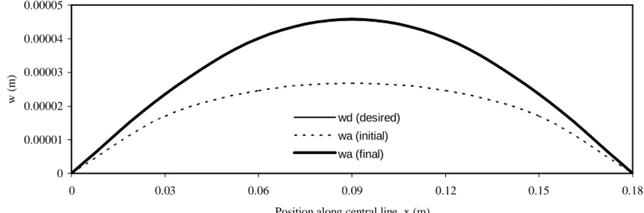
In Figure 2 are shown the central line deflection for mechanical load of 15000 N/m2 (desired curve), the central line deflection for initial actuation with all the patches with same voltage (-180 V), and the achieved central line deflection obtained with the voltage distribution given in Table 1. 0 0.00001 0.00002 0.00003 0.00004 0.00005 0 0.03 0.06 0.09 0.12 0.15 0.18
Position along central line, x (m)
w
(m)
wd (desired) wa (initial) wa (final)
Figure 2. Central line deflections. 5.2 Rectangular panel subjected to uniform distributed load.
A rectangular plate made of S-Glass/Epoxy with the lamination sequence of [0º/45º/-45º/0º] with piezoceramic actuator patches PC5K (lead zirconate titanate), is considered. The plate is simply supported along the shorter sides and free at the longer sides, and is subjected to a
uniformly distributed load. The material properties of the S-Glass/Epoxy layers are GPa,
55
E1 = E2 =16GPa, G12 =7.6GPa, ν12 =0.25, σ1U =1620MPa, σ2U =40MPa, .
MPa 80
U 12 =
σ The thickness of outside layers is 1 mm each and the thickness of inside layers is 0.5 mm each. The material and electric properties of PC5K are E1=E2=60.24 GPa,
GPa, 23
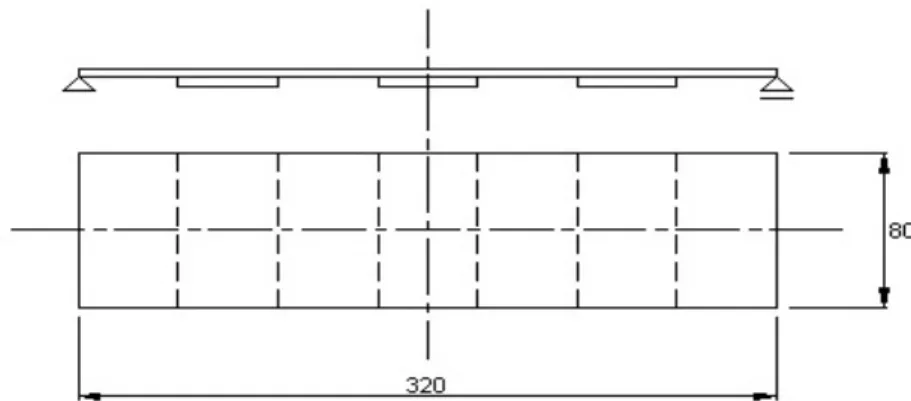
G12= ν12 =0.31, e31 = e32 =-26.72C/m2, p33 =5.04 x 10⁻⁸ F/m, and the yield strengths are the same of the previous application. The thickness of the piezoceramic patches is 0.5 mm. The plate is divided in 7 groups of elements. Here two cases are considered: in the first one for each group of elements correspond an actuator patch, and for the second case only three actuator patches are bonded to the core of the laminated as represented in Figure 3. The shape of the plate is defined by the transversal displacements wi along the longer central
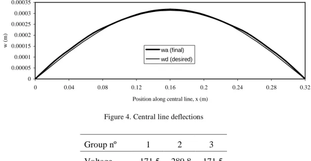
line of the plate. The objective is to find the appropriate electric voltages that should be applied to the seven or three actuators patches in order to minimize the mean-squared error between the actual shape and the desired shape of the plate. The results obtained for the first case are shown in Figure 4 where the central line deflection corresponding to a mechanical load of 500 N/m2 (desired curve), and the achieved central line deflection obtained with the voltage distribution given in Table 2, are represented.
Figure 3. Rectangular panel with three piezoelectric actuator patches
Group nº 1 2 3 4 5 6 7
Voltage -115.1 -78.5 -167.0 -222.4 -167.0 -78.5 -115.1
Table 2. Voltage distribution
For the second case, in Figure 5 are shown the central line deflection corresponding to a mechanical load of 250 N/m2 (desired curve), and the achieved central line deflection obtained with the voltage distribution given in Table 3.
0 0.00005 0.0001 0.00015 0.0002 0.00025 0.0003 0.00035 0 0.04 0.08 0.12 0.16 0.2 0.24 0.28 0.32
Position along central line, x (m)
w
(
m)
wa (final) wd (desired)
Figure 4. Central line deflections
Group nº 1 2 3
Voltage -171.5 -289.8 -171.5
Table 3. Voltage distribution for three actuators patches
0 0.00005 0.0001 0.00015 0.0002 0.00025 0 0.04 0.08 0.12 0.16 0.2 0.24 0.28 0.32
P osit ion along central line x (m)
w
(m)
w a (final) w d (desired)
Figure 5. Central line deflections 5.3 Cylindrical panel subjected to a point load.
A fixed-free symmetric cylindrical panel (Figure 6), with lay-up
[
0º/90º/0º]
integrating piezoelectric actuator patches made of PZT, bonded on lower surface, subjected to a point load, is considered. The geometry of the panel is R = 2540 mm, L = 508 mm, h = 6.1 mm, θ = 0.1 rad, and the material properties and the thicknesses are the same of the first application. The straight edges are fixed and the curved edges are free. A model discretization with (6x6) element mesh is used, and is also divided in the same 9 groups of elements, each one with 8 triangular elements, as in the first application. Each pair of contiguous triangular elementsforms a piezoelectric patch, which cover the entire panel. The optimal voltage distribution is given in Table 4.
Figura 6. Cylindrical panel.
Group nº 1 2 3 4 5 6 7 8 9
Voltaje 153.8 -3.6 -88.3 -147.6 -151.0 -94.7 -12.0 35.5 -443.4 Table 4. Optimal voltage distribution
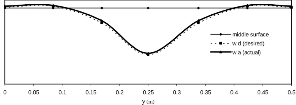
In Figures 7 and 8, are shown the middle surface line, the central line deflection for mechanical point load of 150 N (desired curve), and the achieved central line deflection, obtained with the voltage distribution given in Table 4, respectively in x and y directions.
0 0.05 0.1 0.15 0.2 0.25 0.3 0.35 0.4 0.45 0.5
X (m) middle surface w d (desired) w a (actual)
0 0.05 0.1 0.15 0.2 0.25 0.3 0.35 0.4 0.45 0.5
y (m)
middle surface w d (desired) w a (actual)
Figure 8. Central line deflections in y direction 5.4 Cylindrical panel subjected to a line load.
The same type of structure of the previous application, with the same R, θ, and h, unless the width, now L=127 mm, is subjected to a distributed line load of p=1420 N/m, applied on the top of the panel in a line with the width direction. A model discretization with (10x2) element mesh, 40 triangular elements is used. The panel is divided in the 5 groups of elements, each one with 8 triangular elements, which are collocated symmetrically to the y axis of Figure 6, as is schematically represented in Figure 9.
1 2 3 4 5 5 4 3 2 1
1 2 3 4 5 5 4 3 2 1
Figure 9. Scheme of location of the 5 groups of elements
The optimal voltage distribution is given in Table 5. In Figure 10 are shown the middle surface, the central line deflection for the applied mechanical load (desired curve), and the achieved central line deflection obtained with the voltage distribution given in Table 5.
Group nº 1 2 3 4 5
Voltage -158.3 35.4 -105.0 -42.7 -197.6
Table 5. Optimal voltage distribution 6. CONCLUSIONS
The shape control capability of composite structures covered with piezoelectric layers or patches is investigated, using the finite element method. A finite element based on the Kirchhoff classical theory, has been used. The present model has been validated in Moita et al.
[6], where the solutions for deflection and sensed voltage in a bimorph beam, are compared with the solutions obtained by other authors. The structure shape optimizations had been performed in order to maximize the effect a defined set of actuators, using a gradient-based algorithm. From the Fig. 2, 4, 5, 7, 8 and 10 we can observe that the piezoelectric actuators have the capability of shape control in case of structures subjected to small applied loads.
0 0.05 0.1 0.15 0.2 0.25 0.3 0.35 0.4 0.45 0.5 X (m)
middle surface w d (desired) w a (actual)
Figure 10. Central line deflections in x direction Acknowledgments
The authors thank the financial support of POCTI/FEDER, Fundação para a Ciência e Tecnologia (FCT), POCI/EME/56316/2004, POCI(2010)/FEDER, FP6-2003-NMD-TI3/G3, Contract 13517- Project CASSEM, and CNPq (Brazil) and FARPEJ (Brazil)
REFERENCES
[1] H. Allik and T. Hughes, “Finite Element Method for Piezoelectric Vibration”,
International Journal for Numerical Methods Engineering, Vol. 2, pp. 151-157, (1970).
[2] H.S. Tzou and C.I. Tseng, “Distributed Piezoelectric Sensor/Actuator Design for Dynamic Mesuarement/Control of Distributed Parametric Systems: A Piezoelectric Finite Element Approach”, Journal of Sound and Vibration, Vol. 138, pp. 17-34, (1990) [3] C.Q. Chen, X.M. Wang and Y.P. Shen, “Finite element approach of vibration control
using self-sensing piezoelectric actuators”, Computers and Structures, Vol. 60, n. 3, pp. 505-512, (1996)
[4] B. Samanta, M.C. Ray and R. Bhattacharyya, “Finite element model for active control of intelligent structures”, AIAA Journal, Vol. 34, n. 9, pp. 1885-1893, (1996)
[5] K.Y. Lam, X.Q. Peng, G.R. Liu and J.N. Reddy, “A finite element model for piezoelectric composite laminates”, Smart Material Structures, Vol. 6, pp. 583-591, (1997)
[6] J.S. Moita, C.M. Mota Soares and C.A. Mota Soares, 2005. “Active control of forced vibrations in adaptive structures, using a higher order model”, Composite Structures, Vol. 71, pp. 349-355, (2005)
[7] K.J. Bathe, Finite Element Procedures in Engineering Analysis, Prentice-Hall Inc, Englewood Cliffs, New Jersey, 1982
[8] C. Liang, F.P. Sun and C.A. Rogers, “Determination of design of optimal actuator location and configuration based on actuator power factor”, Journal of Intelligent
Material Systems and Structures, Vol. 6, pp. 456-464, (1995)
[9] R.C. Batra and X.Q. Liang, “The vibration of a rectangular laminated elastic plate with embedded piezoelectric sensors and actuators”, Computers and Structures, Vol. 63, n. 2, pp. 203-216, (1997)
[10] V.M. Franco Correia, C.M. Mota Soares and C.A. Mota Soares, “Refined models for the optimal design of adaptive structures using simulated annealing”, Composite
Structures, Vol. 54, pp. 161-167, (2000)
[11] A. Achuthan, A.K. Keng and W.C. Ming, “Shape control of coupled nonlinear piezoelectric beams”, Smart Material Structures, Vol. 10, pp. 914-924, (2001)
[12] J. Herskovits, P. Mappa, E. Goulard and C.M. Mota Soares, “Mathematical programming models and algorithms for engineering design optimization”, Computer
Methods in Applied Mechanics and Engineering, Vol. 194, pp 3244-3268, (2005)
[13] H.F. Tiersten, Linear Piezoelectric Plate Vibrations. Plenum Press, New Cork, (1969) [14] J.N. Reddy, Mechanics of laminated composite plates and Shells, CRC Press, 2 nd
Edition, New York, (2004)
[15] O.C. Zienckiewicz, The finite element method in engineering sciences, McGraw-Hill, 3rd ed., London, (1977)
[16] J.S. Moita, J.I. Barbosa, C.M. Mota Soares and C.A. Mota Soares, 2000. “Sensitivity Analysis and Optimal Design of Geometric Non-Linear Laminated Plates and Shells”,