Abstract
This paper presents effects of boundary conditions and axial loading on frequency characteristics of rotating laminated conical shells with me-ridional and circumferential stiffeners, i.e., stringers and rings, using Generalized Differential Quadrature Method (GDQM). Hamilton’s prin-ciple is applied when the stiffeners are treated as discrete elements. The conical shells are stiffened at uniform intervals and it is assumed that the stiffeners have similar material and geometric properties. Equations of motion as well as equations of the boundary condition are trans-formed into a set of algebraic equations by applying the GDQM. Ob-tained results discuss the effects of parameters such as rotating veloci-ties, depth to width ratios of the stiffeners, number of stiffeners, cone angles, and boundary conditions on natural frequency of the shell. The results will then be compared with those of other published works particularly with a non-stiffened conical shell and a special case where angle of the stiffened conical shell approaches zero, i.e. a stiffened cylin-drical shell. In addition, another comparison is made with present FE method for a non-rotating stiffened conical shell. These comparisons confirm reliability of the present work as a measure to approximate solutions to the problem of rotating stiffened conical shells.
Keywords
Rotating laminated conical shells, Stringer/ring stiffener, Natural Fre-quency, Generalized Differential Quadrature Method (GDQM), Critical Speed.
Dynamic Analysis and Critical Speed of Rotating Laminated
Conical Shells with Orthogonal Stiffeners Using Generalized
Differential Quadrature Method
1 INTRODUCTION
Circular and conical shell structures are widely being used in many branches of engineering. Vibra-tion of these structures has been also extensively studied [1-3]. Meanwhile, rotating cylindrical and conical shells were studied by many researchers.
Kamran Daneshjou 1, Mostafa Talebitooti 2, *, Roohollah Talebitooti 3, Hamed Saeidi Googarchin 4
1 Prof., Sch. of Mech. Eng., Iran University of Science and Technology, Tehran, Iran 2 Ph.D. Stu., Sch. of Mech. Eng., Iran Uni-versity of Science and Technology, Tehran, Iran
3 Assist. Prof., Sch. of Auto. Eng., Iran University of Science and Technology, Tehran, Iran
4 Ph.D. Stu., Sch. of Mech. Eng. , K.N.T University of Technology, Tehran, Iran
Received 04 Mar 2012 In revised form 12 Jun 2012
A
ij extensional stiffnessN
s(or r) number of stringers (or rings)A
s(or r) cross sectional area of stringers (orrings)
Q
ij reduced stiffness matrixA
* defined by Eq. (51)ij
Q transformed reduced stiffness
matrix
a
minor radius of conical shellR
defined by Eq. (39)B
ij coupling stiffnessr
x radius at any coordinatepoint
x
, θ,z
B
* defined by Eq. (51) rr displacement vectorb
major radius of conical shellS
ij stiffness matrixb
s(or r) width of stiffenerT
ij transformation matrixC
ijs weighting coefficients (Eq. (30))T
kinetic energyD
ij bending stiffnessT
* defined by Eq. (39)d
s(or r) depth of stiffenert
timeE
modulus of Young’s elasticityU
strain energye
middle surface strainU
** defined by Eq. (40)G
ij gyroscope matrix of shellu, v, w
displacement of shell in x, θ andz directions
h
thickness of shellU, V, W
unknown functions in x, y and zdirections (Eq. (36))
G
s(or r) shear modulus of stringers (orrings)
u
s, v
s, w
sdisplacement of stiffeners in x, θ
and z directions
I
identity matrix velocity vectorJ
s(or r) polar moment of stiffenerz
distance of a point in stiffenerfrom shell middle surface
K
ij equivalent stiffness matrixα
cone angleL
length of shellβ
orientation of fibersL
ij differential operator (Eq. (28))κ
middle surface curvaturesM
ij mass matrix of shellν
Poisson’s ratioM
x resultant moment in x directionε
sx strain of stringers in meridionaldirection
N
number of grid pointsε
rθ strain of rings incircumferential direction
n
circumferential wave numberρ
mass densityN
l number of layersω
natural frequency in rad/sN
θ initial hoop tension Π energy functionalN
ax axial loadThey include works by Lam et al. on rotating composites and sandwich-type cylindrical shells [4-5], a comparison study on different thin shell theories in addition to a discussion on the effect of boundary conditions on rotating cylindrical shells [6-7]. Chen et al. used a nine nodes curvilinear
rotat-ing circular conical shell with simply-supported boundary conditions based on Love's first approxi-mation theory [10]. The effect of boundary conditions on free vibration of conical shells, considering the Ritz method, has been studied by Lim and Liew [11].
Although the rotating stiffened conical shell is increasingly being used in many industries, most studies were restricted to the vibration analysis of cylindrical shell. Zhao et al. presented the free vibration analysis of simply supported rotating cross-ply laminated cylindrical shells with axial and circumferential stiffeners, using an energy approach [12]. The effects of these stiffeners were evalu-ated via two methods: stiffeners treevalu-ated as discrete elements; and stiffeners with properties being averaged over the shell surface by smearing method. Jafari and Bagheri investigated the free vibra-tion analysis of simply supported rotating cylindrical shells with circumferential stiffeners, namely rings with non-uniform eccentricity of stiffeners, and non-uniform spacing distribution of stiffeners [13].
In Spite of the widespread use of stiffened conical shells as a base structures of many industrial processes such as water crafts, drive shafts of gas turbines, high-speed centrifugal separators, motors and rotor systems, a few researches are found on this field [14-22]. Besides, these few researches just focus on non-rotating conical shells and the stiffeners have been modeled using smearing method except the work directed by Talebitooti et al. [22]. They assessed natural frequency of rotating stiff-ened conical shell in which the stiffeners are modeled by discrete elements. Crenwelge and Muster analyzed conical shells with stringers and rings using an equivalent orthotropic shell model, and compared the frequencies with experimental results [14]. Rao and Reddy studied the optimum de-sign of stiffened conical shells with natural frequency constraint with the aid of averaging method [15]. Langley developed a dynamic stiffness technique to investigate the stiffened shell structures [16]. This method is based on a singly curved orthogonally stiffened shell element having a constant radius of curvature which is simply supported along the curved edges. The stiffeners are taken to be smeared over surface of the element. “Branched shell approach” has been employed by Raj et al. to examine the effects of rings on the vibration of conical shells considering both theoretical and
exper-imental methods [17]. Mecitoğlu concentrated on the free vibrations of conical shells with orthogonal
stiffeners through the orthotropic material approach [18]. More recently, Goldfeld [19], and Jabareen and Sheinman [20] studied the elastic buckling of stiffened conical shells. Farkas et al. analyzed the optimum design of a ring-stiffened conical shell loaded by external pressure with buckling load constraint [21].
All the previous studies used to only deal with stiffened rotating cylindrical shells, rotating non-stiffened conical shells or non-rotating non-stiffened conical shells while the effects of stiffeners in conical shells were evaluated by an averaging method. Dynamic analysis of rotating stiffened conical shells is rather complex and the common methods used for cylindrical shells are unable to solve these prob-lems. The Generalized Differential Quadrature Method (GDQM) is an efficient numerical technique which is based on the Differential Quadrature (DQ) method. The mathematical fundamentals and recent developments of the GDQ method as well as its major applications in engineering are dis-cussed in detail by Shu [23]. It is worthwhile to note that the increasing interest of researches [24– 31] in this procedure is mainly due to its great simplicity and versatility.
velocities. Moreover, it is investigated how the number of stiffeners affects the frequency characteris-tics. Comparing the results in special cases with those available in the literature and also from FE results, the accuracy of the present analysis will be confirmed.
2 PROBLEM FORMULATION
2.1 Geometrical configuration
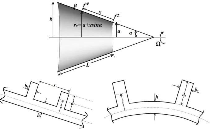
The stiffened conical shell, as shown in Fig. 1, is considered to be thin, laminated and composed of an arbitrary number of layers. In this figure, is the cone angle, is the length, h is the thickness, and are the radii at two ends, and is the constant angular velocity of conical shell about its symmetrical and horizontal axis.
Reference surface of the conical shell is taken to be at its middle surface where an orthogonal
co-ordinate system is fixed, and is a radius at any co-ordinate point .
Dis-placement of the shell in , and directions are denoted by u, v and w, respectively. Depth and width of the stiffeners are symbolized by and , respectively and the ring intervals are
denoted by s. Subscripts indicate the stringer and ring stiffeners, respectively. Displacements
Figure 1 Geometry of stiffened rotating conical shell structure
2.2. Strain energies of shell
The strain energy of the laminated composite conical shell is expressed as:
(01)
where and the strain vector ( ) can be written as:
(02)
where symbols , and are middle surface strains and symbols , and are middle surface curvatures (the subscripts 1 and 2 denote fiber direction and orthogonal direction, respec-tively). Geometric relations of deformation for the reference surface of the conical shell can be writ-ten as [10]:
,
It is assumed that the displacements are continuous functions of the thickness coordinate, which results in continuous transverse strains.
Meanwhile, stiffness matrix for a cross-ply laminated shell is given by:
(04)
where , and are extensional, coupling and bending
stiff-ness matrices, respectively. For an arbitrary laminated composite shell, they can be rewritten as:
(05)
where is the total number of layers in the laminated composite conical shell. Parameters and
denote distance from the shell reference surface to the outer and inner surface of layer as
shown in Fig. 2.
is the element of transformed reduced stiffness matrix for the kth layer and it is defined as:
(06)
where is transformation matrix of the principal material coordinate and the shell coordinates
(07)
where is orientation of the fibers and is reduced stiffness matrix defined as:
(07)
Moreover, material constants in the reduced stiffness matrix are defined as:
(09)
where and are the elastic moduli, is the shear modulus, and and are the Pois-son’s ratios.
Figure 2 Cross-sectional view of the laminated conical shell
It should be noted that the work is carried out on the shell due to centrifugal force generated by rotation. The work done on the shell can be written as [22]:
where Nq is the initial hoop stress due to centrifugal force which is given by:
(11)
Besides, the work done on the shell due to axial forced is described as:
(12)
where is the axial load on edge of shell in xdirection. The effect of and are null for both simply supported and clamped boundary conditions [32].
2.3 Kinetic energy of the shell
Kinetic energy of the rotating conical shell is expressed as:
(13)
where is the velocity vector at any point of the shell given by:
(14)
Here, presents differentiation with respect to time.
In Eq. (14) the displacement vector is written as:
(15)
where , and respectively denote the unit vectors in , and directions for nonrotating frame.
Having substituted Eqs. (14) and (15) into Eq. (13), the kinetic energy expression of the shell can be expanded in the form below:
(16)
2.4 Stiffener energies
inte-gral part of the shell. Meanwhile, when stiffeners of equal strength are closely and evenly spaced, the stiffened shell can be modeled as an equivalent orthotropic shell (smearing method). However, as the stiffener spacing increases or the wavelength of vibration becomes smaller than the stiffener spacing, determination of dynamic characteristics for the stiffened shell cannot be accurate anymore. Thus, a more general model needs the stiffeners to be treated as discrete elements. When modeled in this respect, it is advantageous to use non-uniform eccentricity, unequally spaced and different materials for stiffener stiffeners. In order to maintain displacement compatibility between the stiffeners and the stiffened shell, a special transformation is used which includes coupling effects due to eccentric placement of the stiffener. It should be also noted that the displacements vary through depth of the stiffeners. Therefore, displacement of a point at distance z from the shell middle surface can be ex-plained by shell displacement function [15]:
(17)
The strain of stringers in the meridional direction and the strain of rings in the circumferential direction are respectively defined as:
(18)
(19)
Using discrete stiffener theory, the strain energy for the stringer can be written as [22]:
(20)
where and are torsional stiffness and cross sectional area of the stringer, respectively,
with being the number of stringers.
The strain energy of the ring can be written as [22]:
(21)
where and are torsional stiffness and cross sectional area of the ring, respectively,
while is the number of rings.
(22)
(23)
where is density of the stringer (or ring).
In the case of stringers, the hoop stress created due to centrifugal force is negligible. However, the work done on the ring by this hoop stress can be calculated in a similar way to that of the shell itself. Therefore, the work expressions for the stringer and ring would be:
(24)
(25)
2.5. Governing Equations of motion
The governing differential equations of motion can be derived using Hamilton’s principle:
(26)
where is variation of the energy functional and t denotes the time. The energy functional of a stiffened rotating conical shell can thus be written as:
(27)
(28)
where the coefficients are differential operators of .
2.6 Assumed-mode method and GDQM solution of the governing equations
The GDQM is based on a simple mathematical concept that any sufficiently smooth function in a
do-main can be expressed approximately as an order polynomial in the overall domain. In
other words, at a discrete mesh point in a domain, the derivative of a sufficiently smooth function with respect to a coordinate direction can be approximated by taking a weighted linear sum of the functional values at all discrete mesh points in coordinate direction. Thus the partial derivatives of a function as an example, at a point ( , )x qi i are expressed as [23]:
(29)
where is the number of grid points and f can be taken as either u, v or w; and parameters of
are respective weighting coefficients related to the order derivatives which are obtained as fol-lows:
If , namely for the first order derivative, then:
(30)
and:
(31)
where is the first derivative of and can be defined as:
(32)
(33)
and:
(34)
Since the coordinate distribution and the number of discrete grid points can be arbitrarily chosen in the implementation of GDQM, following distributions of the grid points toward meridional x di-rection will be used in this formulation:
(35)
It is noteworthy that the grid points should be distributed in such a way that one grid point is provided in every ring location.
Vibration modes of the laminated circular conical shell are characterized by , the number of circumferential waves and the natural frequency, . A general expression for displacement field is assumed to have the form of a product with unknown continuous smooth functions in the meridional direction and trigonometric function along the circumferential direction, that is to say [27]:
(36)
By substituting the displacement field (36) into the set of partial differential governing equations (28) in temporal-spatial domain, a set of ordinary differential equations with variable coefficients toward meridional direction is produced as:
0 =
*U*
Τ (37)
where is an unknown spatial function vector of mode shape which
describes the distribution of vibrational amplitude in meridional x direction, while
is a differential operator matrix of and is defined as:
where coefficients of and are given in detail in Appendix A.
With imposing Eq. (29) on Eq. (37) and rearrangement of the Eq. (37) with respect to the order of derivative, the approximate governing equations in the form of linear discrete algebraic equations are obtained as follows:
(39)
where N is the number of total discrete grid points in meridional x direction and U* * is given by:
(40)
where:
(41)
Thus, the whole system of differential equation has been discretized and the the following set of linear algebraic equations will be produced from general combination of these equations:
(42)
In the above equations, vectors
{ }
d and{ }
b with dimensions 3N - 8 and 8, denote the un-knowns at the sampling points within interior domain and those on the boundary, respectively and can be written as:{ }
{
( ) ( )
(
) (
)
( ) ( )
(
) (
)
( )
( )
(
)
(
)
}
2 3 2 1
2 3 2 1
3 4 3 2
, ,..., , ,
, ,..., , ,
, ,..., ,
T
N N
N N
T
N N
d U x U x U x U x
V x V x V x V x
W x W x W x W x
-
--
--
-=
(43)
The dimensions of , and are and dimension of is
.
Similarly, discretized form of the boundary conditions becomes:
(45)
The dimension of is and dimension of is .
In current application of GDQM, five boundary conditions are considered for rotating conical shells, namely:
a) Clamped at both edges (Cs-Cl):
(46)
b) Simply supported at both edges (Ss-Sl):
(47)
c) Simply supported at small edge - clamped at large edge (Ss-Cl):
(48)
d) Clamped at small edge - simply supported at large edge (Cs-Sl):
(49)
e) Free at both edges (Fs-Fl):
(50)
Using Eq. (45) to eliminate boundary degrees of freedom
{ }
b from Eq. (44), it can be concluded that:Eq. (51) is a non-standard eigenvalue equation. For a given frequency, it can be equivalently transformed into a standard form of eigenvalue equation as [27]:
(52)
where I is a identity matrix.
Using a conventional eigenvalue approach, the standard eigenvalue equation (52) can be solved, and eigenvalues are obtained. From these eigenvalues, the two eigenvalues are chosen for
which the absolute of real values are the smallest. One of these eigenvalues is negative and corre-sponds to backward wave, and the other one is positive and correcorre-sponds to forward wave. In the case of a stationary conical shell, these two eigenvalues are identical and the vibration of the conical shell is a standing wave motion.
3 NUMERICAL RESULTS
In the presentation of results shown by figures, the backward and forward waves are presented as a solid line and a dashed line, respectively, with the unit of rotating speed W being in rps (revolutions per second). In addition, five boundary conditions are considered here for the rotating conical shell. These boundary conditions include fully clamped (Cs-Cl), fully simply supported (Ss-Sl), fully unsup-ported (Fs-Fl), simply supunsup-ported at small edge - clamped at large edge (Ss-Cl), and clamped at small edge - simply supported at large edge (Cs-Sl). Material properties of the shells used in this study are given in Table 1. In addition, unless otherwise stated, geometrical dimensions and material proper-ties of the stiffeners used in the present study are given in Table 2.
Table 1 Mechanical properties of the material
Modulus of Elasticity
(GPa) Poisson's Ratio
Modulus of Rigidity (GPa)
Density (kg/m3)
Isotropic E=7.6 υ=0.3 G=2.9 ρ=1643
Orthotropic E22=7.6
E11=2.5 E22 υ12=0.26 G12=4.1 ρ=1643
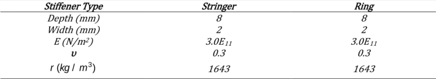
Table 2 Geometrical parameters and material properties of the stiffeners used in this study
Ring Stringer
Stiffener Type
8 8
Depth (mm)
2 2
Width (mm)
3.0E11
3.0E11
E (N/m2)
0.3 0.3
υ
1643 1643
3
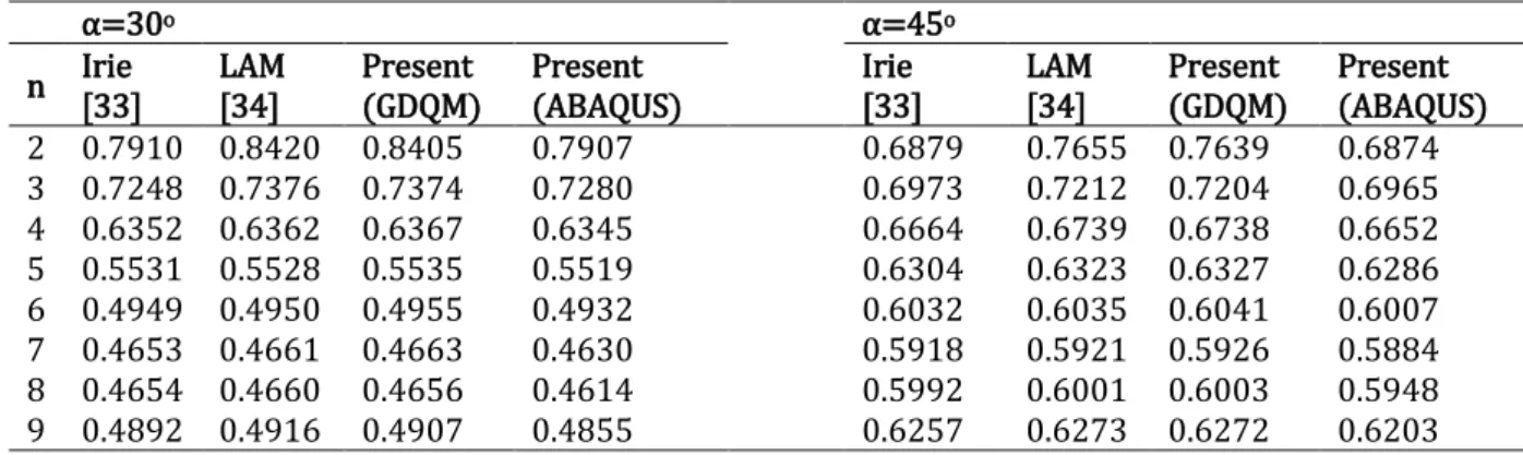
The GDQM is especially suitable for considering global characteristics such as free vibration or buckling analyses. Numerical accuracy of the GDQM, with excellent weighting characteristics, is high-ly reliable, and its implementation is both simple and efficient. To show versatility and efficiency of the present analysis, three comparisons are made with the available results in the existing literature. The initial comparisons are made with Refs. [33-34] for a non-rotating conical shell with Ss-Sl boundary condition and also the one with Cs-Cl boundary condition by taking Ω=0 into the present formulations as shown in Table 3 and Table 4, respectively.
Table 3 Comparison of frequency parameter for a non-rotating isotropic conical shell with Ss-Sl
boundary condition (m=1, υ=0.3, h/b=0.01, Lsinα/b=0.25)
α=45o α=30o Present (ABAQUS) Present (GDQM) LAM [34] Irie [33] Present (ABAQUS) Present (GDQM) LAM [34] Irie [33] n 0.6874 0.7639 0.7655 0.6879 0.7907 0.8405 0.8420 0.7910 2 0.6965 0.7204 0.7212 0.6973 0.7280 0.7374 0.7376 0.7248 3 0.6652 0.6738 0.6739 0.6664 0.6345 0.6367 0.6362 0.6352 4 0.6286 0.6327 0.6323 0.6304 0.5519 0.5535 0.5528 0.5531 5 0.6007 0.6041 0.6035 0.6032 0.4932 0.4955 0.4950 0.4949 6 0.5884 0.5926 0.5921 0.5918 0.4630 0.4663 0.4661 0.4653 7 0.5948 0.6003 0.6001 0.5992 0.4614 0.4656 0.4660 0.4654 8 0.6203 0.6272 0.6273 0.6257 0.4855 0.4907 0.4916 0.4892 9
Table 4 Comparison of frequency parameter f = wb
(
1- u2)
r / E for a non-rotating isotropic conical shell with Cs-Clboundary condition (m=1, υ=0.3, h/b=0.01, Lsinα/b=0.5)
α=60o α=45o Present (ABAQUS) Present (GDQM) LAM [34] Irie [33] Present (ABAQUS) Present (GDQM) LAM [34] Irie [33] n 0.6312 0.6324 0.6449 0.6316 0.8117 0.8128 0.8452 0.8120 1 0.5520 0.5535 0.5568 0.5523 0.6693 0.6713 0.6803 0.6696 2 0.4780 0.4798 0.4818 0.4785 0.5425 0.5449 0.5553 0.5430 3 0.4290 0.4308 0.4361 0.4298 0.4561 0.4588 0.4778 0.4570 4 0.4082 0.4098 0.4202 0.4093 0.4093 0.4108 0.4395 0.4095 5 0.4144 0.4113 ─ ─ 0.3954 0.3959 ─ ─ 6 0.4447 0.4385 ─ ─ 0.4131 0.4054 ─ ─ 7 0.4949 0.4834 ─ ─ 0.4553 0.4442 ─ ─ 8 0.5611 0.5496 ─ ─ 0.5157 0.5033 ─ ─ 9
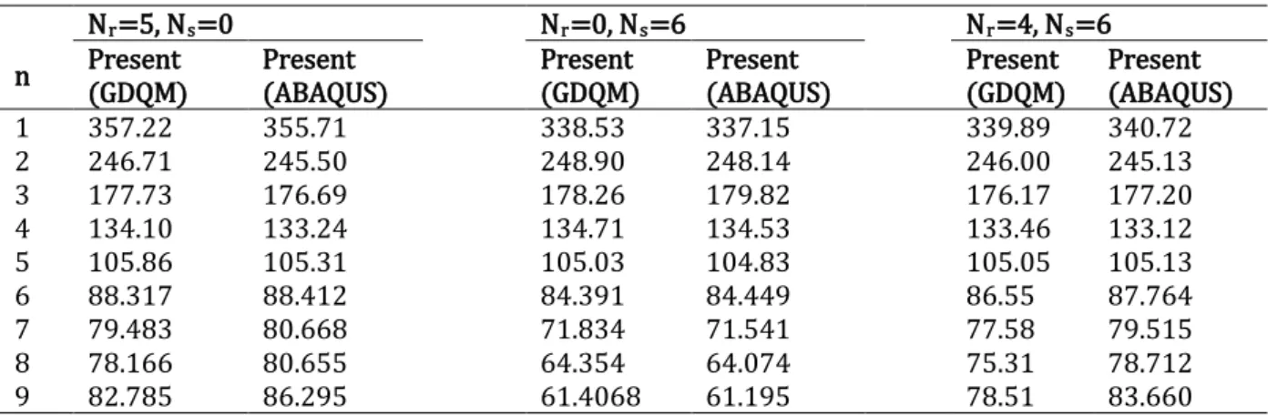
Table 5 Comparison of frequency for a non-rotating stiffened isotropic conical shell with Cs-Cl boundary condition (m=1, υ=0.3,
h=2mm, L=1m, a=0.5m, α=20o)
Nr=4, Ns=6
Nr=0, Ns=6
Nr=5, Ns=0
Present (ABAQUS) Present (GDQM) Present (ABAQUS) Present (GDQM) Present (ABAQUS) Present (GDQM) n 340.72 339.89 337.15 338.53 355.71 357.22 1 245.13 246.00 248.14 248.90 245.50 246.71 2 177.20 176.17 179.82 178.26 176.69 177.73 3 133.12 133.46 134.53 134.71 133.24 134.10 4 105.13 105.05 104.83 105.03 105.31 105.86 5 87.764 86.55 84.449 84.391 88.412 88.317 6 79.515 77.58 71.541 71.834 80.668 79.483 7 78.712 75.31 64.074 64.354 80.655 78.166 8 83.660 78.51 61.195 61.4068 86.295 82.785 9
Table 6 Comparison of frequency for a non-rotating stiffened isotropic conical shell with Ss-Sl boundary condition (m=1, υ=0.3,
h=2mm, L=1m, a=0.5m, α=20o)
Nr=4, Ns=6
Nr=0, Ns=6
Nr=5, Ns=0
Present (ABAQUS) Present (GDQM) Present (ABAQUS) Present (GDQM) Present (ABAQUS) Present (GDQM) n 231.75 234.39 236.02 237.52 232.33 234.98 2 149.01 150.57 151.59 152.66 148.56 151.89 3 99.751 102.25 101.07 103.32 99.618 102.71 4 72.429 74.309 71.681 73.844 72.498 74.94 5 59.587 59.902 54.856 56.535 60.240 61.42 6 57.689 56.446 46.504 48.299 59.097 58.54 7 63.096 60.002 44.378 45.944 65.204 63.13 8 72.336 67.588 47.207 47.856 74.750 71.92 9
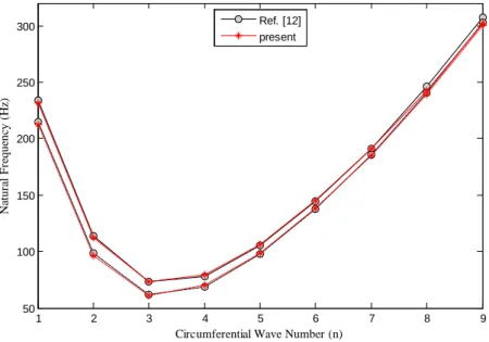
Figure 3 Variation of natural frequencies for the rotating orthogonally stiffened composite cylindrical shell with circumferential wave number in comparison between results of the present study and those reported in Ref. [12]. (L=2m, a=0.5m, h=2.5mm, m=1,
Ω=10rev/s, Ns=5, Nr=15, [0o/90o/0o])
Figure 4 Variation of natural frequencies for the rotating orthogonally stiffened composite conical shell with circumferential wave
number in comparison between results of the present study and those reported in Ref. [22]. (L/a=10, h/a=0.002, α=15o, m=1,
Ω=10rev/s, Ns=20, Nr=10, [0o/90o/0o])
The last comparison is made with Ref. [22] for a rotating stiffened laminated conical shell being simply supported at both edges as shown in Fig. 4. With numerical comparisons shown in Tables 3-6 and Figs. 3-4, it is evident that the presented results are in a good agreement with the data available in the literature and FE results, which demonstrates accuracy of the current work.
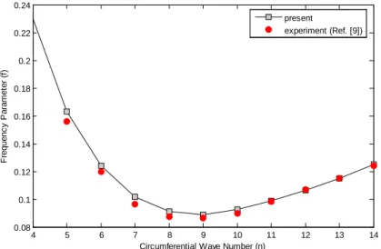
In addition, the computed frequency parameter for non-rotating un-stiffened
isotropic conical shell with free boundary conditions were compared to those obtained
experimen-1 2 3 4 5 6 7 8 9
50 100 150 200 250 300
Circumferential Wave Number (n)
N
at
u
ral
F
req
u
en
cy
(
H
z)
Ref. [12] present
1 2 3 4 5 6 7 8 9 10 11 12
100 200 300 400 500 600 700
Circumferential Wave Number (n)
N
at
ur
al
F
requenc
y
(
rad/
s
)
tally from Ref. [9] as shown in Fig(5). Comparing the present results with those of experiments re-veals an excellent agreement. The slight divergence is attributed to satisfaction of the assumed boundary conditions among these two methods.
Figure 5 Variation of natural frequencies for the un-stiffened isotropic conical shell with circumferential wave number in compari-son between results of the present study and those reported in Ref. [9]. (L/a=2.53, h/a=0.00127, α=30.2o, m=1, Ω=0rev/s)
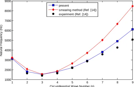
In Fig. (6), an additional comparison is made between the theoretically and experimentally produced natural frequencies of orthogonal stiffened non-rotating conical shell by Ref. [14] and the theory proposed here. The present theory estimates more accurate results than the smearing method, since the former assumes the stiffeners as discrete elements while the latter considers the properties of the stiffeners averaged throughout the shell. Moreover, the present theory is in good agreement with the experimental results. In higher modes (n ³ 8) the difference is occurred between the present theory and the experimental results. This seems to occur because the shell stiffened with widely sep-arated stiffeners is less rigid upon bending than expected before. On the other hand, in present method the stiffener is expected to be moved with structure as an integral part which may be differ-ent from a real structure in experimdiffer-ents. There may be also some other parameters such as the ef-fects of boundary condition and the errors of experimental setup which cause discrepancy. However, the present method is found more reliable than the smearing method. There is just 10% of discrep-ancy comparing the present work with those of experiment, whereas the inconsistency of 41% was presented by Ref. [14], comparing the experimental results with those of smearing method.
4 5 6 7 8 9 10 11 12 13 14
0.08 0.1 0.12 0.14 0.16 0.18 0.2 0.22 0.24
Circumferential Wave Number (n)
F
requenc
y
P
ar
am
et
er
(
f)
alp=30.2,h=0.256mm, b=201.9mm,L=401.4,steel
present
Figure 6 Variation of natural frequencies for the orthogonally stiffened isotropic conical shell with circumferential wave number in
comparison between results of the present study and those reported in Ref. [14]. (L/a=3.06, h/a=0.0292, α=10o, m=1, Ω=0rev/s, Ns=6, Nr=3)
Fig. 7 (a-b) demonstrates that, for different boundary conditions considered here, variation of the frequency for unstiffened and stiffened conical shell decreases rapidly at first, and then raised mono-tonically by increasing the circumferential wave number, n. The Cs-Cl conical shell has the highest frequency, followed by the Ss-Cl , Cs-Sl and S-S shells. This behavior was simply expected before, as Cs-Cl is a fully restrained boundary condition. At lower circumferential wave numbers, relatively considerable differences between frequencies of the four boundary conditions are observed, imply-ing that the influence of boundary condition is significant. At higher circumferential wave numbers, the natural frequencies of Ss-Cl and Cs-Cl, and also those of Cs-Sl and Ss-Sl boundary conditions con-verge as a result of shortening the wavelengths. It should be noted that the effects of boundary condi-tion are more significant for the unstiffened shell where the results of different boundary condicondi-tions are getting closer at mode number 8, though this occurred for the stiffened shell at mode number 6.
1 2 3 4 5 6 7 8 9
1000 2000 3000 4000 5000 6000 7000 8000 9000
Circumferential Wave Number (n)
N at ur al F requenc y ( H z ) present
smearing method (Ref. [14]) experiment (Ref. [14])
2 4 6 8 10 12 14
20 40 60 80 100 120 140 160
Circumferential Wave Number (n)
Figure 7 Variation of natural frequencies for the composite conical shell having circumferential wave number for different boundary conditions, (a) unstiffened shell, (b) stiffened shell Ns=Nr=10. (L=3m, a=0.5m, h=3mm, α=30o,
m=1, Ω=0, [0o/90o/0o])
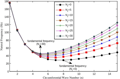
Fig. 8 highlights the effects arisen from number of rings on frequencies of the stiffened non-rotating conical shell at fully clamped boundary conditions. No stringers are used in this case. It can be observed from this figure that at lower circumferential wave numbers, the number of rings demonstrates no significant effect. However, in high circumferential wave numbers, the frequency is raised by increasing the number of rings, whereas the increasing rate of gradient becomes small. However, the number of circumferential waves with occurrence of the fundamental frequency de-creases when the number of rings is enhanced. For example, the fundamental frequency occurred at
n=8 for Nr=0, and at n=5 for Nr=30.
Figure 8 Variation of natural frequencies for the composite conical shell with circumferential wave number at various numbers of
rings (L=3m, a=0.5m, h=3mm, α=20o, m=1, Ω=0, [0o/90o/0o], Cs-Cl)
Fig. 9 depicts the effects from number of stringers on natural frequency of the non-rotating stringer-stiffened conical shell. In this case, the numbers of stringers are 0, 10 and 20, where no rings
2 4 6 8 10 12 14
20 40 60 80 100 120 140 160 180
Circumferential Wave Number (n)
N at u ral F req u en cy ( H z) stiff,L=3,a=0.5,h=3,m=1,th=15,[0,90,0],OM=0,Ns=10,Nr=10 Ss-Sl Cs-Cl Ss-Cl Cs-Sl coincident wave number
b
2 4 6 8 10 12 14
0 20 40 60 80 100 120 140 160 180
Circumferential Wave Number (n)
N at u ral F req u en cy ( H z) L=3,a=0.5,h=3,th=20,m=1,[0,90,0],OM=0,Cs-Cl
Nr=0 N
r=5
Nr=10 Nr=15 N
r=20
Nr=25 Nr=30
fundamental frequency (N
r=0)
ential wave. However, at lower circumferential wave numbers, particularly in frequencies smaller than the fundamental one, the frequency decreases slightly by increasing the number of stringers. This is because inertial terms of the stiffened shell are more considerable than those of the stiffness.
Figure 9 Variation of natural frequencies for the composite conical shell with circumferential wave number in various numbers of
stringers (L=3m, a=0.5m, h=3mm, α=20o, m=1, Ω=0, [0o/90o/0o], Cs-Cl)
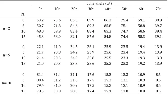
The effects of cone angles on natural frequency of the conical shells stiffened with rings and stringers at different circumferential wave numbers is listed in Tables 7 and 8, respectively. It is noteworthy that the number of rings in lower circumferential wave numbers, namely, n=2, are negli-gible for all cone angles. However, at greater number of circumferential wave the results are affected by the ring numbers. This occurrence is not the same in different cone angles. In smaller cone angles, the increasing rate is very significant. For instance, the natural frequencies are enhanced up to 304% in α=0o when Nr is increased to 15. However, this effect is rather reduced for large cone angles; as in
α=70o the results are increased 108%. This is mainly due to the fact that flexural rigidity of the ring
elements decreases at greater radius, while the terms of mass inertial increase. With greater number of the stringers a slight reduction is seen in natural frequency as listed in Table 8. This descending rate is more considerable at lower circumferential wave number and smaller cone angle. Therefore, the use of stringer is not recommended unless the buckling phenomenon is significant. The trend of results for natural frequency with respect to the cone angles in lower circumferential wave numbers contain a maximum point beyond which the trend will become descending.
Table 7 Variation of natural frequency for laminated conical shell with respect to number of rings and cone angles at various cir-cumferential wave number (L=3m, a=0.5m, h=2mm, Ω=0, [0o/90o/0o], Ss-Sl)
cone angle (αo)
0o 10o 20o 30o 40o 50o 60o 70o
Nr
n=2
0 53.2 73.6 85.8 89.9 86.3 75.4 59.1 39.9
5 53.4 73.2 85.4 89.6 86.1 75.5 59.4 40.3
10 53.6 72.8 84.9 89.2 85.9 75.5 59.6 40.6
15 53.8 72.5 84.5 88.8 85.6 75.5 59.8 40.8
n=5
0 22.1 21.0 24.5 26.1 25.9 23.5 19.4 13.9
5 53.9 30.7 28.3 28.1 27.0 24.5 20.3 15.0
10 71.2 36.7 31.1 29.6 28.0 25.2 21.0 15.7
2 4 6 8 10 12 14
20 40 60 80 100 120 140 160 180
Circumferential Wave Number (n)
N
at
u
ral
F
req
u
en
cy
(
H
z)
L=3,a=0.5,h=3,m=1,[0,90,0],th=20,OM=0,Nr=0,CC
15 83.6 41.1 33.2 30.8 28.8 25.8 21.6 16.3
n=10
0 81.4 31.4 21.1 17.6 15.3 13.2 10.9 8.5
5 211.1 71.2 40.5 29.4 24.0 20.1 16.8 13.6
10 279.9 90.0 51.0 35.5 28.3 23.6 19.6 16.0
15 329.5 101.6 58.7 40.0 31.4 25.9 21.6 17.7
Table 8 Variation of natural frequency for laminated conical shell with respect to number of stringers and cone angles at various
circumferential wave number (L=3m, a=0.5m, h=2mm, Ω=0, [0o/90o/0o], Ss-Sl)
cone angle (αo)
0o 10o 20o 30o 40o 50o 60o 70o
Ns
n=2
0 53.2 73.6 85.8 89.9 86.3 75.4 59.1 39.9
5 50.7 71.8 84.6 89.2 85.8 75.1 58.8 39.7
10 48.0 69.9 83.4 88.4 85.3 74.7 58.6 39.4
15 45.3 68.0 82.1 87.6 84.8 74.4 58.3 39.1
n=5
0 22.1 21.0 24.5 26.1 25.9 23.5 19.4 13.9
5 21.7 20.8 24.2 25.9 25.6 23.4 19.4 13.9
10 21.4 20.5 24.0 25.8 25.5 23.3 19.3 13.9
15 21.0 20.3 23.8 25.6 25.3 23.2 19.2 13.9
n=10
0 81.4 31.4 21.1 17.6 15.3 13.2 10.9 8.5
5 80.4 31.2 21.0 17.5 15.3 13.1 10.9 8.5
10 79.4 31.0 20.9 17.5 15.2 13.1 10.9 8.5
15 78.5 30.8 20.8 17.4 15.1 13.0 10.8 8.5
Table 9 summarizes the effect of various shell lengths on natural frequency of the ring-stiffened shells with similar interval at different wave numbers. As mentioned above, natural frequencies are diminished by increasing the shell length as expected before. There is an exception for α=0o, where for greater wave numbers, particularly n=15, increasing the shell length leads to enhanced corre-sponding natural frequencies. It is also noteworthy that fundamental wave numbers of the conical shell with α=0o, 15o are reduced monotonically with enlargement of the length. Although the trend is rather different at α=45o, 60o.
Table 9 Variation of natural frequency (Hz) for the laminated conical shell with respect to length of shells and cone angles in various circumferential wave number (a=1m, h=1mm, Ω=0, [0o/90o/0o], Cs-Cl)
L(m) 2 5 8
α n=1 n=nf* n=15 n=1 n=nf n=15 n=1 n=nf n=15
0o 247.8 50.7
(n=7) 145.9 102.5 23.1 (n=5) 157.3 59.4
14.9
(n=4) 160.1
15o 227.5 44.6
(n=8) 84.0 104.7 19.0 (n=7) 43.6 67.2
12.2
30o 188.4
(n=9) 58.7 94.9 16.1 (n=8) 23.2 63.2 9.8 (n=9) 12.7
45o 134.6 32.8
(n=9) 45.2 71.5 13.2 (n=9) 16.2 48.4
7.8
(n=11) 8.7
60o 84.4 26.0
(n=9) 35.9 44.5
10.1
(n=10) 12.1 30.1
5.8
(n=11) 6.4
Fig. 10(a-d) illustrates the effects of depth and width of ring cross-section on natural frequencies of backward waves for stiffened rotating conical shells having different cone angles. It is observed that at great circumferential wave numbers, frequencies of the shells generally increase with depth of the ring in both forward and backward waves. Moreover, the difference between curves becomes insignificant when the cone angle is raised. This is due to the fact that, inertia terms of the rings be-come more significant than the stiffening terms influenced by long depth of the rings where effective radius of the shell is increased.
2 4 6 8 10 12 14
0 200 400 600 800 1000 1200
Circumferential Wave Number (n)
N at u ral F req u en cy ( H z) L=3,a=0.5,m=1,Nr=10,Ns=0,th=0,CS,[0,90,0],OM=10
dr/br=1 dr/br=2 dr/br=4 dr/br=8
a
a
2 4 6 8 10 12 14
50 100 150 200 250 300
Circumferential Wave Number (n)
N at u ral F req u en cy ( H z) L=3,a=0.5,m=1,Nr=10,Ns=0,th=15,CS,[0,90,0],OM=10
dr/br=1 dr/br=2 d
r/br=4
dr/br=8
Figure 10 (continued) Variation of natural frequencies for the rotating ring-stiffened composite conical shell with circumferential wave number at various depth to width ratios, (a) α=0o, (b) α=15o, (c) α=30o, (d) α=45o. (L=3m, a=0.5m, h=3mm, m=1, Nr =10,
Ar=30mm2, Ω=10rev/sec, [0o/90o/0o], Cs-Sl)
Figure 10 Variation of natural frequencies for the rotating ring-stiffened composite conical shell with circumferential wave number
at various depth to width ratios, (a) α=0o, (b) α=15o, (c) α=30o, (d) α=45o. (L=3m, a=0.5m, h=3mm, m=1, Nr =10, Ar=30mm2,
Ω=10rev/sec, [0o/90o/0o], Cs-Sl)
The phenomenon of critical speed of the shell is illustrated in Fig. 11. The critical speed of the rotating shell corresponds to rotational speed of the shell at which the forward wave intersects ab-scissa. At this inter-section, an unstable phenomenon possibly appears as the forward wave becomes standing with respect to the traveling coordinate and thus would be ready to switch to backward
2 4 6 8 10 12 14
40 60 80 100 120 140 160 180
Circumferential Wave Number (n)
N at u ral F req u en cy ( H z) L=3,a=0.5,m=1,Nr=10,Ns=0,th=30,CS,[0,90,0],OM=10
dr/br=1 dr/br=2 dr/br=4 dr/br=8
c
c
2 4 6 8 10 12 14
40 60 80 100 120 140 160
Circumferential Wave Number (n)
N at u ral F req u en cy ( H z) L=3,a=0.5,m=1,Nr=10,Ns=0,th=45,CS,[0,90,0],OM=10,Ar=30mm2
dr/br=1 dr/br=2 dr/br=4 dr/br=8
nify whirling amplitude.
For various cone angles, α, the relationship between frequency and rotating speed at mode (1, 1) in the case of Ss-Sl boundary condition, is shown in Fig. 11. Contrary to cylindrical shell, variation of the natural frequency with rotating speed shows non-linearity in conical shell. This non-linearity is intensified with increased cone angle. Furthermore, critical speeds of the conical shell are enhanced due to greater cone angles, but there is no general rule to compare natural frequencies of the shells.
Figure 11 Variation of natural frequency of the rotating stiffened laminated conical shell with rotating speed at various cone angles (L=3m, a=0.5m, h=3mm, m=n=1, Ns=Nr=10, [0o/90o/0o], Ss-Sl)
Variations of natural frequency with rotating speed at different circumferential wave numbers are shown in Fig. 12(a-d) for various cone angles of the rotating stiffened conical shell with simply sup-ported boundary conditions at both edges. The results in Fig. 12(a) indicate that critical speed of the cylindrical shell occurs in mode n=1, but, as can be seen in Fig. 12(b-d), the phenomenon of critical speed of the conical shell is observed for all circumferential wave numbers. Having compared the effects of rotating speed on the natural frequency, a significant difference between conical and cylin-drical shells is noticed. It is noteworthy that the critical speed for n=1 increases for greater values of the cone angle, contrary to all other circumferential wave numbers where the critical speeds de-crease rapidly. For example, the critical speed of the conical shell at n=1 is enhanced from 107(rev/sec) to 115(rev/sec) when the cone angles are altered from 30o to 45o. On the other hand, the critical speeds at n=2 are suddenly reduced from 359(rev/sec) to 270(rev/sec).
There is also another important discrepancy between rotating cylindrical and conical shells which is called divergence instability here. As seen from Fig. 12(a), the difference between frequencies of backward and forward waves would increase when the rotating speed is raised. In the case of the conical shell, although the difference between frequencies of forward and backward waves increases initially, it decreases then. These two curves tend to overlap in a specific range of rotating speed. The divergence instability of the rotating shell corresponds to rotational speed of the shell where the frequencies of forward and backward waves are the same. The rotating speeds of divergence instabil-ity are generally higher than those of the critical one. This phenomenon is illustrated in Fig. 12(b-d).
0 20 40 60 80 100 120 140 160 180 200 220 0
50 100 150 200 250 300 350
Rotating Speed (rps)
N
at
u
ral
F
req
u
en
cy
(
H
z)
L=3,a=0.5,h=3,[0,90,0],m=1,n=1,Ns=Nr=10,SS
α=0o
α=15o
α=30o
α=45o
As can be clearly seen, raising the cone angle imposes a reduction in the rotating speed at which the divergence instability is occurred.
Figure 12 (continued) Variation of natural frequencies for the rotating stiffened composite conical shell with rotating speed at
vari-ous cone angles, (a) α=0o, (b) α=15o, (c) α=30o, (d) α=45o. (L=5m, a=0.5m, h=3mm, m=n=1, Ns=Nr=10, [0o/90o/0o], Ss-Sl)
0 10 20 30 40 50 60 70 80 90 100
0 50 100 150 200 250 300
Rotating Speed (rps)
N
at
u
ral
F
req
u
en
cy
(
H
z)
L=5,a=0.5,m=1,Ns=Nr=10,[0,90,0],th=0,SS,h=3
n=1 n=2 n=3
a
0 50 100 150 200 250 300 350 400
0 100 200 300 400 500 600
Rotating Speed (rps)
N
at
u
ral
F
req
u
en
cy
(
H
z)
L=5,a=0.5,m=1,Ns=Nr=10,[0,90,0],th=15,SS,h=3
n=1 n=2 n=3
Figure 12 Variation of natural frequencies for the rotating stiffened composite conical shell with rotating speed at various cone
angles, (a) α=0o, (b) α=15o, (c) α=30o, (d) α=45o. (L=5m, a=0.5m, h=3mm, m=n=1, Ns=Nr=10, [0o/90o/0o], Ss-Sl)
In Fig. 13(a-d), four configurations of the conical shell, namely at α=0o, 15o, 30o and 45o, are used
to investigate the effect of axial load on natural frequency. In this figure, is used to address criti-cal global buckling load of the conicriti-cal shell, while axial compressive and tensile loads are represented by negative and positive signs, respectively. It is important to note that the compressive axial load must be a fraction of static critical global buckling load. To achieve the static critical global buckling load, the global buckling differential equations could be produced by neglecting the terms involving
Ω and ω in Eq. (52). The responses to both compressive and tensile axial loads are generally
predict-able for all modes having a downward and upward shift, respectively. This is expected since tensile axial load causes the shell to become stiffer. Noteworthy is that the effect of axial load on fundamen-tal frequency is more significant than others. Moreover, the sensitivity rate of natural frequency to compressive load is greater than that of natural frequency to the tensile load.
0 50 100 150 200 250 300 350 400
0 50 100 150 200 250 300 350 400
Rotating Speed (rps)
N at u ral F req u en cy ( H z) n=1 n=2 n=3 359 107
0 50 100 150 200 250 300 350 400
0 50 100 150 200 250 300
Rotating Speed (rps)
Figure 13 (continued) Variation of natural frequencies for the non-rotating stiffened composite conical shell with circumferential
wave number at various cone angles, (a) α=0o, (b) α=15o, (c) α=30o, (d) α=45o. (L=1m, a=0.25m, h=3mm, m=1, Ns=Nr=5, [0o/90o/0o], Cs-Cl)
1 2 3 4 5 6 7 8 9
200 300 400 500 600 700 800 900
Circumferential Wave Number (n)
N
at
ur
al
F
requenc
y
(
H
z
)
,
,
,
,
,[ ,
, ],
a
N xa/N xcr=0
N xa/N xcr=-0.4
N xa/N xcr=0.4
a
1 2 3 4 5 6 7 8 9
100 150 200 250 300 350 400 450 500
Circumferential Wave Number (n)
N
at
ur
al
F
requenc
y
(
H
z
)
b
N xa/N xcr=0
N xa/N xcr=-0.4
N xa/N xcr=0.4
Figure 13 Variation of natural frequencies for the non-rotating stiffened composite conical shell with circumferential wave number
at various cone angles, (a) α=0o, (b) α=15o, (c) α=30o, (d) α=45o. (L=1m, a=0.25m, h=3mm, m=1, Ns=Nr=5, [0o/90o/0o], Cs-Cl)
4. CONCLUSIONS
Generalized Differential Quadrature Method has been used in this paper to study free vibration and critical speed of the rotating stiffened laminated conical shells by treating the stiffeners as discrete elements. In addition, the FEM code was developed by the commercial FE software, ABAQUS. The results obtained from GDQM are validated in special cases with the results of present FE model and also those of other researchers. Discussions are made on the effects of boundary conditions, number
1 2 3 4 5 6 7 8 9 10
100 150 200 250 300 350 400 450
Circumferential Wave Number (n)
N
at
ur
al
F
requenc
y
(
H
z
)
c
N xa/ Nxcr=0
N xa/ Nxcr=-0.4
N xa/ Nxcr=0.4
c
1 2 3 4 5 6 7 8 9 10
50 100 150 200 250 300 350
Circumferential Wave Number (n)
N
at
ur
al
F
requenc
y
(
H
z
)
d
N xa/Nxcr=0
N xa/Nxcr=-0.4
N xa/Nxcr=0.4
of stiffeners, axial load, cone angle and rotating speed. Finally, the following results have been ob-tained:
1- The effect arisen from number of rings on natural frequency at lower circumferential wave bers is negligible for all cone angles. However, in higher modes the results are affected by ring num-bers with the variety of results having different cone angles being recognized. The natural frequen-cies are enhanced 304% at α=0o, while Nr is increased to 15. However, this rate will be reduced for
high cone angles as in α=70o the results are increased just 108%.
2- The trend of results for natural frequency with respect to cone angles at lower circumferential wave numbers contains a maximum point in which the trend for higher wave numbers becomes de-scending.
3- The present method is in agreement with the experiments. There is only an average of 10% dis-crepancy between the present work and those of experimental results for a widely stiffened conical shell from n=2 to n=9. However the inconsistency of 41% was reported by other researchers with the results of smearing method.
4- By increasing the number of stringers, a slight reduction is noticed in natural frequency. There-fore, application of stringer is not recommended unless the buckling phenomenon is significant.
5- The fundamental wave numbers of the conical shell with α=0o, 15o are monotonically reduced
with increasing the length, whereas a rather adverse trend is found at α=45o, 60o.
[1] Leissa, A.W.: Vibration of shells, NASA, SP-288 (1973)
[2] Soedel, W.: Vibrations of shells and plates, Revised and expanded, 2nd Ed., New York: Marcel Dekker (1996)
[3] Reddy, J.N.: Mechanics of laminated composite plates and shells: theory and analysis, 2nd Ed., CRC press (2004)
[4] Lam, K.Y., Loy, C.T.: On vibrations of thin rotating laminated composite cylindrical shells. Composites Engineer-ing 4, 1153_1167 (1994)
[5] Lam, K.Y., Loy, C.T.: Free vibrations of a rotating multi-layered cylindrical shell. Int J Solids Struct 32, 647_663 (1995)
[6] Lam, K.Y., Loy, C.T.: Analysis of rotating laminated cylindrical shells by different thin shell theories. J Sound Vibr
186, 23_25 (1995)
[7] Hua, L., Lam, K.Y.: Frequency characteristics of a thin rotating cylindrical shell using the generalized differential quadrature method. Int J Mech Sci 40, 443_459 (1998)
[8] Chen, Y., Zhao, H.B., Shea, Z.P.: Vibrations of high speed rotating shells with calculations for cylindrical shells. J Sound Vibr 160, 137_160 (1993)
[9] Lindholm, U.S., Hu, W.C.L.: Non-symmetric transverse vibrations of truncated conical shells. Intl J Mech Sci 8 (9), 561_579 (1966)
[10] Lam, K.Y., Hua, L.: Vibration analysis of a rotating truncated circular conical shell. Int J Solids Struct 34 (17), 2183_2197 (1997)
[11] Lim, C.W., Liew, K.M.: Vibratory behaviour of shallow conical shells by a global Ritz formulation. Eng Struct
17(1), 63_70 (1995)
[12] Zhao, X., Liew, K.M., Ng, T.Y.: Vibration of rotating cross-ply laminated circular cylindrical shells with stringer and ring stiffeners. Int J Solids Struct 39, 529_545 (2002)
[13] Jafari, A.A., Bagheri, M.: Free vibration of rotating ring stiffened cylindrical shells with non-uniform stiffener distribution. J Sound Vibr 296, 353_376 (2006)
[14] Crenwelge, O.E., Muster, D.: Free vibration of ring and stringer stiffened conical shells. J Acoust Soc Am 46, 176_185 (1969)
[15] Rao, S.S., Reddy, E.S.: Optimum design of stiffened conical shells with natural frequency constraints. Comput Struct 14, 103_110 (1981)
[16] Langley, R.S.: A dynamic stiffness technique for the vibration analysis of stiffened shell structures. J Sound Vibr
156, 521_540 (1992)
[17] Raj, D.M., Narayanan, R., Khadakkar, A.G., Paramasivam, V.: Effect of ring stiffeners on vibration of cylindrical and conical shell models. J Sound Vibr 179, 413_426 (1995)
[18] Mecitoğlu, Z.: Vibration characteristics of a stiffened conical shell. J Sound Vibr 197 (2), 191_206 (1996)
[19] Goldfeld, Y.: Elastic buckling and imperfection sensitivity of generally stiffened conical shells. AIAA Journal 45 (3), 721_729 (2007)
[20] Jabareen, M., Sheinman, I.: Stability of imperfect stiffened conical shells. Int J Solids Struct 46 (10), 2111_2125 (2009)
[21] Farkas, J., Jármai, K., Orbán, F.: Cost minimization of a ring-stiffened conical shell loaded by external pres-sure. Welding in the World 52 (5-6), 110_115 (2008)
[22] Talebitooti, M., Ghayour, M., Ziaei-Rad, S., Talebitooti, R.: Free vibrations of rotating composite conical shells with stringer and ring stiffeners. Arch Appl Mech 80 (3), 201_215 (2010)
[23] Shu, C.: Differential Quadrature and Its Application in Engineering, Springer, Berlin (2000)
[24] Wang, Y., Liu, R., Wang, X.: On free vibration analysis of nonlinear piezoelectric circular shallow spherical shells by the differential quadrature element method. J Sound Vib 245, 179_185 (2001)
[25] Liew, K.M., Ng, T.Y., Zhang, J.Z.: Differential quadrature-layerwise modeling technique for three dimensional analysis of cross-ply laminated plates of various edge supports. Comput Meth Appl Mech Eng 191, 3811_3832 (2002)
[26] Karami, G., Malekzadeh, P.: A new differential quadrature methodology for beam analysis and the associated differential quadrature element method. Comput Meth Appl Mech Eng 191, 3509_3526 (2002)
[27] Ng, T.Y., Hua, L., Lam, K.Y.: Generalized differential quadrature for free vibration of rotating composite laminated conical shell with various boundary conditions. Int J Mech Sci 45, 567_587 (2003)
[28] Huang, Y.Q., Li, Q.S.: Bending and buckling analysis of antisymmetric laminates using the moving least square differential quadrature method. Comput Meth Appl Mech Eng 193, 3471_3492 (2004)
[29] Wang, X., Wang, Y.: Free vibration analyses of thin sector plates by the new version of differential quadrature method. Comput Meth Appl Mech Eng 193, 3957_3971 (2004)
[31] Haftchenari, H., Darvizeh, M., Darvizeh, A., Ansari, R., Sharama, C.B.: Dynamic analysis of composite cylindrical shells using differential quadrature method(DQM). Compos Struct 78, 292_298 (2007)
[32] Nedelcu, M.: GBT formulation to analyse the buckling behaviour of isotropic conical shells. Thin-Walled Struct
49, 812-_818 (2011)
[33] Irie, T., Yamada, G., Tanaka, K.: Natural frequencies of truncated conical shells. J Sound Vibr 92, 447_453 (1984) [34] Lam, K.Y., Hua, L.: Influence of boundary conditions on the frequency characteristics of a rotating truncated
circular conical shell. J Sound Vibr 223 (2), 171_195 (1999)
Appendix A
(A1)
(A2)
(A4)
(A5)
(A6)
(A7)
(A8)
(A9)
(A10)
(A12)
(A13)
(A14)
(A16)
(A19)
(A22)
(A23)
![Figure 9 Variation of natural frequencies for the composite conical shell with circumferential wave number in various numbers of stringers (L=3m, a=0.5m, h=3mm, α=20 o , m=1, Ω=0, [ 0 o /90 o /0 o ], Cs-Cl)](https://thumb-eu.123doks.com/thumbv2/123dok_br/18884861.423584/22.807.227.614.176.427/figure-variation-natural-frequencies-composite-conical-circumferential-stringers.webp)