Sander Gabaldo
[email protected] University of Campinas School of Mechanical Engineering, CP 6122 13083-970 Campinas, SP, Brazil
Anselmo Eduardo Diniz
[email protected] University of Campinas School of Mechanical Engineering, CP 6122 13083-970 Campinas, SP, Brazil
Cássio Luiz F. Andrade
[email protected] Tupy Fundições Joinville, SC, Brazil
Wilson Luiz Guesser
[email protected] Tupy Fundições CCT – Engenharia Mecânica UDESC – Universidade do Estado de Santa Catarina Joinville, SC, Brazil
Performance of Carbide and Ceramic
Tools in the Milling of Compact
Graphite Iron – CGI
Grey cast iron (GCI) is the most common material used in diesel engine blocks. However, to increase the pressures in the combustion chamber when this kind of alloy is used, it is necessary to increase the block wall thickness, what raises its weight and, consequently, does not fulfill the requirements. Thus, the compacted graphite iron (CGI) appears as an alternative for such application. It has characteristics of heat conductivity and damping similar to the GCI, but with superior mechanical properties, making possible the manufacturing of lighter engines with better performance. However, the use of CGI presents as disadvantage its worse machinability, when compared with GCI, stimulating development of machining techniques and cutting tool materials.The goal of this work is to analyze the performance of two tool materials (carbide and ceramic Si3N4) in the finishing milling of the fire face of the engine block made of CGI. To reach this goal these two materials were compared in terms of wear mechanisms and tool life in different cutting speeds. The main conclusion was that, for conditions similar to those used in this work, carbide is better than ceramic in terms of tool life in the milling CGI.
Keywords: compacted graphite iron, milling cutter, carbides, ceramic, wear mechanism
Compact Graphite Iron - CGI
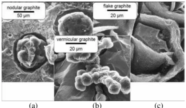
1Compact graphite iron is a material with intermediary properties between grey cast iron (GCI) and ductile cast iron (Sahm et al., 2002).Like in the GCI, the graphite particles in the CGI are flat, long, randomly oriented and interconnected. In the ductile iron they are in form of nodules (Warrick et al., 1999). However, as it can be seen in Fig. 1(b), the “worms” (as the graphite particles in the CGI are called) have something in common with the nodules of the ductile iron (Fig. 1(a)), since both are much smaller than the graphite lamellas of the GCI (Fig. 1(c)). On the other hand, the morphology of CGI graphites is compact and with rounded tips, what makes the nucleation and growth of cracks more difficult than in the GCI. The sharp and lamellar graphites of the GCI with smooth surfaces (Fig. 1(c)) make this material more fragile than the other two (Löhe, 2005).
The CGI alloys have good properties of mechanical strength, ductility, toughness, thermal shocks, damping and heat conductivity (Mocellin et al., 2004). These properties are better for the CGI part functioning, but make its machinability worse than the machinability of GCI.
Compared with GCI, the CGI presents some advantages like reduction of the wall thickness of the parts for a same load, reduction of the safety factor due to a smaller variation of the cast properties, reduction of the fragile fractures during manufacturing, assembly and service due to its higher ductility and strength (Dawson, 1999).
Compared with ductile cast iron, it can be said that with CGI it is easier to produce complex cast parts and the residual stresses are smaller due to the higher heat conductivity (what also helps to increase cutting tool life). Moreover, it presents smaller Young modulus and better machinability (Guesser, 2004).
Paper accepted May, 2010. Technical Editor: Fernando A. Rochinha
(a) (b) (c)
Figure 1. Graphite Morphology in the ductile (a), compact (b) and grey (c) irons (Dawson et al., 2001).
Milling of CGI engine blocks
Besides the worm graphite particles, a certain percentage of spheroidal graphite nodules is also present in the CGI. As the nodularity increases, the material strenght also increases making the forces needed to cut the material higher. Moreover, with the nodularity growth, the heat conductivity decreases, decreasing machinabilty even more (Dawson, 2002).
A factor that makes the engine blocks even more difficult to be machined is the great number of interruptions on the surface. Special care has to be taken in the mill cutter choice, because very positive tools reduce cutting force, but may generate tool life relatively lower when compared to the cutters with negative geometry, due to their small impact resistance.
good values of roughness and flatness are to improve the rigidity of the tool and workpiece fixation systems and the tool trajectory (en
I cutting, which is ano
rried out in the machining of CGI with these tool materials.
Ca
suit
cut
trance and exit of the tool in the cutting).
In general, by comparing the CGI milling with the GCI milling, it consumes 20% more of cutting power and is more abrasive, even when two alloys with similar hardness are compared. Besides that, cutting temperatures are also higher during CG
ther factor to harm tool life (Dawson, 1999).
Due to the higher ductility of the CGI compared to GCI, the contact between chip and tool rake face is larger and, so, the chips generated have stronger tendency to adhesion and, when high cutting speeds are used, there is a strong tendency of tool craterization. The most used tool materials to cut CGI alloys are carbide and silicon nitride ceramics and both are going to be tested in this work. Therefore, the next items describe some experiments already ca
rbide Tools for CGI
Carbide is the most important tool material used in the industries nowadays, due to its good combination of hot hardness, abrasion resistance and toughness. The variation of its chemical composition makes it possible to obtain a wide range of these properties (Ferraresi, 1970). Besides the chemical composition, another important factor to define the carbide properties is the grain size. The smaller the grain size, the higher the packing factor and, therefore, the higher the hardness, wear resistance and toughness of the material. It is possible to produce carbides with grain size as small as 0.1 µm (Diniz et al., 2008). Also, the carbide heat conductivity decreases as its grain size decreases, what hinders the heat flow through the tool, tends to increase tool life and makes it able to be used with high cutting speeds (Diniz et al., 2008).
The use of carbide coatings have increased as time elapses. They have been applied to join in the same body the toughness of substrate (usually carbide with high amount of cobalt) with the extreme hardness of the coatings. Consequently, the use of coated tools made possible the elevation of cutting parameters with more stable processes, without tool breakage and cracks. The coating layer thickness varies from 2 to 22 µm. The main properties of the coatings are high abrasion resistance, chemical stability in high
ting temperatures and low friction coefficient (Sandvik, 1994). Milling experiments were carried out by a tool manufacturer cutting CGI with 98% of perlite and average hardness of 230 HB. The cutting conditions were those typically used in rough operations with a face milling cutter of 200 mm of diameter and 1 tooth. The tool entering angle was 75° and the rake angle was 5° (Walter AG, 1997). The insert ISO code was SPMW120408-A57 and different carbide grades were tested. The tool coatings were TiCN, Al2O3 and
TiN on the flank face and TiCN and Al2O3 on the rake face. The
experiments were carried out without cutting fluid and the tool life criterion was flank wear > 0,3 mm. The input variables were cutting speed (vc = 140, 220, 280 and 340 m/min) and carbide grade and
coat
K15 grades always reached longer tool lives than the K2
in terms of tool life in both, milling of CGI and GCI. Besides that, ing according to table 1.
The main results pointed out that tool life decreases as cutting speed increases mainly when it increased from 140 to 220 m/min. Moreover, the
5 grades.
Other experiments were carried out (Walter AG, 1997) comparing milling of CGI and GCI (GG25) with cutting speed of 352 m/min (cutting speed typically used in the milling of the GCI alloy GG25) and 2 different tool materials (2 K15 carbide grades). Both workpiece materials presented an average hardness of 230 HB and 98% of perlite. The K15-2 grade reached the best performance
the lives of the tools used in the GCI milling were, on average, four times longer than those used in the CGI milling.
Table 1. Carbide grades and coating used in the experiments (Walter AG, 1997)*.
Grade Grain size (ųm) Cobalt (%) Coating thickness (ųm)
K15-1 1-3 6 6
K15-2 1-3 6 12
K25-1 1-3 8 6
K25-2 1-3 8 12
*
All tools were coated with a MT-CVD process and two layers of TiCN + Kappa Al2O3.
Ceramic Material for CGI
The ceramic tools make it possible the use of high cutting speeds. Therefore, the machine tools which use this kind of tool material must have high cutting power and mechanical stiffness. The ceramic used as cutting tool is made of fine grains with high density, containing less than 2% of porosity (Trent and Wright, 2000).
Tool chemical stability is very important when the process is carried out with high cutting speeds and, consequently, high temperatures. Some ceramic grades are very chemically stable with iron, like the pure and mixed ceramics based on Al2O3. To the
machining of cast irons, tool chemical stability is not very important, since the chemical kind of wear (diffusion) occurs mainly on the tool rake face. As the chip formed in the machining of cast iron is very small, it does not friction so much with this face, harming the formation of this kind of wear. On the other hand, the ceramics based on Si3N4 have low chemical stability with iron.
However, as they are tougher than the Al2O3 -based ceramics,they
are used mainly in the machining of cast iron, especially in interrupted processes like milling, where tool temperature is not very high (Diniz et al., 2008).
Ceramic materials have low thermal conductivity. Therefore, the tool receives a small percentage of the total heat generated, what is supposedly good for the tool. However, this low thermal conductivity decreases the amount of heat flowing into it and, so, makes the regions of the tool close to the chip-tool and workpiece-tool interfaces hotter. Another typical property of ceramics is the low toughness, which makes cracks and breakages occurrence easier (Machado et al., 2009).
In general, ceramics have high capacity to withstand high temperatures, high resistance against abrasive wear, high hardness and compression strength.
In this work, the Si3N4 (Sialon) -based ceramic is going to be
used. This material has higher toughness when compared to the Al2O3 -based ceramic and low thermal expansion coefficient,
which results in good resistance to thermal shocks (Trent and Wright, 2000).
The main shortcoming of this material is, as already said, the low chemical stability with iron. That is the reason for its use mainly in the machining of cast iron (short chips) with interrupted cutting like milling (low temperatures).
Materials, Equipments and Experimental Procedures The milling experiments were carried out in a machining center with 22 kW in the main motor and maximum spindle of 12,000 rpm. The carbide inserts used had ISO code ODMW060508 HC-K15 and the ceramic inserts were Si3N4 -based (Sialon) with ISO code
The cutting edge micro geometry used did not have chip breaker and had a chamfer to protect the edge with dimensions of 0.1 mm x 20º. The coating used for both ceramic and carbide tools is a multi-layer PVD coating (nc-AlCrN)/(a-Si3N4), with a nano composed
structure with 40 GPa of hardness. It presents high resistance to oxidation at high temperatures (>1150°C) and high toughness. The grains of the nano structure are embedded into the matrix of Si3N4 of
the coating. The silicon increases the toughness of the coating, decreases the residual stress and avoids the grain growth, keeping an excellent hardness (Platit, 2008).
The milling cutter had diameter of 63 mm with 4 teeth (cutting edges) and 43° of entering angle. The cutter + insert assembly provides a double positive geometry (7º of axial rake angle and 3º of radial rake angle). This geometry helps to decrease cutting forces and vibration tendency.
The workpieces were prepared to simulate the milling of the Ford V-6 engine block fire face in a reduced scale of 3.17 times. Figure 2 shows a scheme of the workpieces used in the experiments.
The chemical composition of the CGI alloy used in the experiments is the same used in the engine blocks (see Table 2).
Figure 2. Scheme of the workpieces
Table 2. Chemical composition of the CGI alloy used in the experiments.
C (%) Si (%) Mn (%) S (%) Ti (%)
3.44 2.22 0.31 0.005 0.01
Before micro structure analysis of the workpiece samples, they passed through polishing and 3% Nital etching. The results of this analysis are shown in Table 3.
Brinell hardness measurements were made on samples of the workpiece with sphere of 2.5 mm diameter and load of 187.5 Kgf. The results’ average value was 228 HB.
Table 3. Percentage and forms of the graphites and phases of the material matrix.
Material
% CGI graphites
% Nodular graphites
Graphite form
% Perlite
% Ferrite
CGI 93-94 6-7 III e VI 92 8
An experiment finished when at least three cutting edges reached maximum flank wear (always the highest value of flank wear along a cutting edge) of VBmáx = 0.3 mm and this moment was
considered the end of tool life. If chipping occurred on the cutting edge, the tool was considered in the end of its life when the chipping extension was either equal or higher than 0.5 mm. Several times during each experiment the cutter was removed from the machine in order to measure the flank wear of all the cutting edges. These measurements were carried out in an optical microscope with 50 times amplification. The worn tools (after the end of tool life) were taken to a Scanning electronic microscope (SEM) with Energy dispersive system (EDS) in order to analyze the tool wear mechanism.
Dry cutting was used in all experiments. Depth of cut (ap) and
feed per tooth (fz) were kept constant in all experiments and were,
respectively, 1 mm and 0.10 mm. The cutting speeds and the tool materials used in each experiment are shown in Table 4. It is important to say that the first two speeds used (350 and 420 m/min) are close to the speeds recommended for the milling with carbide tools and the third and fourth speeds (680 and 850 m/min) are recommended for the milling with ceramic (Si3N4) tools (Walter,
2009). Each experiment was carried out three times.
Table 4. Input variables in all experiments (HC – carbide, CN – ceramic).
Experiment Cutting speed
(m/min) Tool material
1 350 HC-K15
2 420 HC-K15
3 680 HC-K15
4 680 CN-K20
5 850 HC-K15
6 850 CN-K20
Results and Discussion
Figure 3 shows the average tool lives (in cutting time and in volume of chip removed) for both carbide and ceramic tools, in different cutting speeds. Tool life dispersions are also shown in the figure.
Tests with carbide and ceramic
Figure 3. Tool lives for the experiments with carbide and ceramic tools.
0 2 4 6 8 10 12 14 16 18 20
HC - 350 m/min HC - 420 m/min HC - 680 m/min CN - 680 m/min HC - 850 m/min CN - 850 m/min
Ti
m
e
0 100 200 300 400 500 600 700 800
Vo
lu
m
e
cm
³)
mi
n
)
(
(
It can be seen in this Fig. 3 that, when cutting speed increased from 350 to 420 m/min, the carbide tool life in cutting time decreased, but remained constant when it was measured in volume of material removed. Above 420 m/min, carbide tool lives decreased in both cutting time and volume of material removed. Also for ceramic tools, when cutting speed increased from 680 to 850 m/min, tool life in cutting time decreased a little, but remained constant when measured in volume of material removed.
With cutting speeds of 680 and 850 m/min, the carbide tools presented tool lives much longer than the ceramic inserts, what definitely was not expected. There are some hypotheses to explain this superiority of carbide over ceramic. The first could be the free carbides present in the workpiece structure (what was not verified in the analysis). These carbides (mainly titanium carbides) have hardness even greater than the hardness of the tool. Therefore, they could cause chipping and even breakage of the cutting edge. Machado et all (2009) states that an average carbide insert presents toughness (Kh) of 9.6 MPa K
-1
while an average Si3N4 based
ceramic tool has this property with the value of 6.5 MPa K-1. Therefore, this lower toughness of the ceramic would make it more sensitive to chippings and breakage and, therefore, would cause it to have shorter life.
A second hypothesis is related to the wear mechanism and kind of operation. As this work deals with finish operations, the maximum flank wear was limited to 0.3 mm. Up to this wear level, the coating still plays an important role in the tool wear resistance. Therefore, the carbide tool could have a wear resistance similar to the ceramic tool, since both presented the same coating. If this hypothesis is correct and if the experiments were carried out considering a rough operation, where the tool wear could reach higher levels (up to 1 mm or even more), the carbide tools would wear much faster after they had lost the coating, while the ceramic tool would keep the same wear rate with any level of flank wear, since the carbide substrate hardness is much lower than the coating hardness, what is not true for the ceramic tool (Diniz et al., 2008). In such situation, the ceramic tool would supposedly present longer tool lives than the carbide tools.
In order to explain whether these hypotheses are true or there are other explanations for the fact that the carbide tools presented longer lives than ceramic, the worn tools were taken to a scanning electronic microscope (SEM). In this equipment, a more detailed analysis of the wear land could be done and, so, a better understanding of the wear mechanism can be reached. The results of this analysis will be shown in the next item.
Before showing the results of the SEM analysis, it is important to see the results of the values of flank wear along tool life, which are shown in Fig. 4. It can be seen in this figure that flank wear presented a continuous growth along tool life in all experiments, without any significant variation of the wear rate. This result indicates that very likely the wear mechanism was the same along tool life in all experiments.
Analysis of the tool wear mechanism
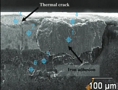
Figures 5 and 6 shows a detailed view (SEM picture and EDS graphics) of the flank wear land of the carbide tool used in the experiment with cutting speed of 420 m/min. The cutting edge used with cutting speed of 350 m/min presented a wear land very similar to this one and, so, will not be shown here.
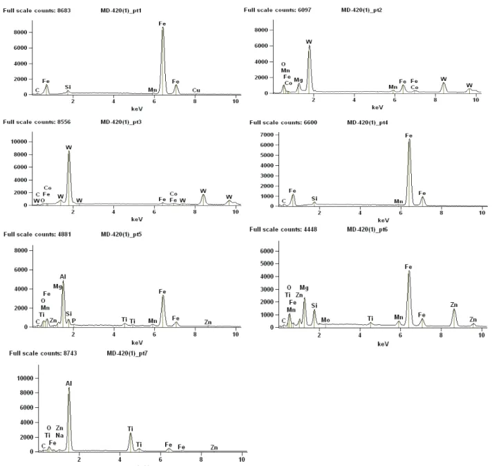
Using EDS analysis (Fig. 6), it could be seen that the region of point 1 of the figure is plenty of iron from the workpiece adhered on the flank face. At points 2 and 3, tungsten from the tool substrate was found, due to the loss of coating caused by the wear. In point 5, which is in the periphery of the wear land, aluminum from the coating and iron from the workpiece material were found. Again in
point 6, aluminum from the coating was found. Therefore, it seems that attrition (cyclical adhesion and removal of workpiece/chip material from the tool, which also causes removal of tool particles – (Trent and Wright, 2000)) was the main tool wear mechanism that caused the end of tool life in the experiments with 350 and 420 m/min. The portion of the wear land with adhered workpiece material would have this material removed with the progress of the cutting and the portion with the tool substrate material exposed would be with adhered workpiece material as the cutting went on.
It is not clear the presence of micro chippings on the cutting edge, but it can be seen a crack between points 3 and 2.
Figure 7 shows a detailed view of the flank wear land of the carbide tool used in the experiment with cutting speed of 680 m/min.
Using EDS analysis (the graphics of EDS will not be shown anymore to avoid unnecessary repetitions), it can be seen that points 1 and 5 of the figure were full of iron from the workpiece adhered on the tool flank face. However, the iron presence was not strong enough to be seen in the magnified photo, as occurred in the tool used with lower cutting speeds (vc = 420 m/min, Fig. 5). In the
points 3, 4 and 6, tungsten from the tool substrate can be seen, what indicates that, due to the wear, the tool had already lost its coating on that region.
It is also possible to see in the figure the presence of microchippings and cracks perpendicular to the cutting edge, which indicates that they had thermal origin (temperature variation). These cracks are caused by an alternating expansion and contraction of the surface layers of the milling tool as they were heated during cutting and cooled by conduction into the body of the tool during the intervals between cuts (Trent and Wright, 2000). These results show that the attrition phenomenon, which caused the end of tool life when vc = 350 and 420 m/min were
used, is still present, but cracks of thermal origin also contributed to make the tool reach its end of life. Very likely, the adhered workpiece material penetrated into the cracks and made their growth faster, decreasing, in such a way, tool life.
Flank wear against cutting time for all experiments
0 0,05 0,1 0,15 0,2 0,25 0,3 0,35
1,50 3,00 4,50 6,00 7,50 9,00 10,50 12,00 13,50 15,00 16,50 18,00
Time (min)
F
lan
k
w
ear
(m
m
) HC - 350 m/min
HC - 420 m/min HC - 680 m/min CN - 680 m/min HC - 850 m/min CN - 850 m/min
Figure 5. Flank wear land of the carbide tool used with cutting speed of 420 m/min (end of tool life).
Figure 8 shows a detailed view of the flank wear land of the carbide tool used in the experiment with cutting speed of 850 m/min.
Also, through EDS analysis, it could be seen a strong presence of iron from the workpiece adhered to the wear land mainly in point 1 of the figure. In point 2 (periphery of the wear land), aluminum from the tool coating was found. It is also possible to see in this analysis the presence of both chippings on the cutting edge and a thermal crack between points 4 and 2.
Again, due to the strong adhesion of iron from the workpiece on the flank wear land, it can be concluded that attrition was one of the most important wear mechanism that made the tool reach its end of life. However, a question has to be raised: why in a higher cutting speed (850 m/min) the number of thermal cracks found on the wear land was smaller than in the tool used to cut in a lower cutting speed (680 m/min), where supposedly the temperature variation in each revolution is also smaller? A possible answer to this question is that the thermal cracks were under the adhered iron layer on the wear land and, due to the cyclical removal of the adhered material typical of attrition, if the picture had been taken in another moment of the cutting time, it could be very similar to the picture of Fig. 6, i.e., the adhered layer would not be there and it would show the presence of several cracks and just a little bit of adhered material. Another possible answer is that the chipping seen in this figure got rid of the thermal cracks eventually present.
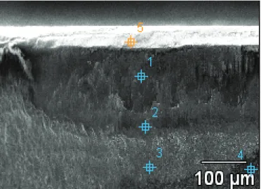
Figure 9 shows a detailed view of the flank wear land of the ceramic tool used in the experiment with cutting speed of 680 m/min. It can be seen that the kind of wear changed completely. Neither any layer of adhered material nor any kind of crack can be seen in this picture.
With the help of EDS analysis, it could be seen that silicon (one of the basic elements of the ceramic used) was present in the points 1 and 5 of the picture. In the points 2, 3 and 4, chromium from the coating was found, since these points are in the periphery of the wear land. In spite of having the same coating material of the carbide tool and, supposedly, the same friction coefficient, there was no adhesion of material from the workpiece on the flank face of the tool. Based on the smooth appearance of the wear land, on the lack of abrasive scratches parallel to the cutting directions (typical of abrasive wear), on the low chemical stability of the Si3N4 and on the
presence of iron in small amounts on the wear land, it can be concluded that the main wear mechanism was, likely, diffusion (Trent and Wright, 2000). This result indicates that diffusion is not
just a mechanism caused by the contact between chip and tool rake face where seizure between chip and tool is present. Even the contact between workpiece and tool flank face, which does not present the same strong interaction of the contact on the rake face, can promote diffusive wear in tools with low chemical stability with iron, like the Si3N4 tool used in this work.
Thermal crack
Figure 10 shows a detailed view of the flank wear land of the ceramic tool used in the experiment with cutting speed of 850 m/min. The appearance of this wear is very similar to that found on the cutting edge used to cut with vc = 680 m/min, i.e., the wear land is
very smooth and it can´t be seen either cracks or layer of workpiece adhered material on the wear land. There is just a little of workpiece adhered material in the periphery of the wear land (point 1 of the figure).
Iron adhesion
By EDS analysis, it can be seen that silicon from the tool was found in the points 2 and 3 and chromium from the tool coating was found in point 4 (periphery of the wear land). In the point 1, a little amount of iron from the workpiece was found adhered on the flank face. Again, based on the smooth appearance of the wear land, on the lack of abrasive scratches parallel to the cutting directions (typical of abrasive wear), on the low chemical stability of the Si3N4and on the presence of iron in small amounts on the wear land, it can be concluded that the main wear mechanism was diffusion. Based on the results taken from the analysis of Figs. 9 and 10, it can be concluded that the coating was not able to increase the chemical stability of this ceramic tool.
Unlike the experiments with carbide tools, thermal cracks and chippings could not be seen on the cutting edge when ceramic tools were used, what was not expected, since ceramic has lower toughness than carbide. This fact indicates that the toughness of the material together with the extra reinforcement caused by the chamfer on the cutting edge were sufficient to withstand the frequent shocks against the workpiece, typical of the milling process. It is important to remember that the workpiece was full of other interruptions (like in the face of fire of an engine block). Therefore, the number of shocks of the tool against the workpiece in each revolution was much higher than when a continuous surface is milled. But now a question has to be raised: why carbide tools presented chips and cracks if it is tougher than ceramic? Perhaps, if the ceramic tool was more resistant against diffusion and, consequently, the ceramic tool lives were longer, the higher number of shocks on the cutting edge would cause the tool fatigue and, consequently, would generate these chippings on the cutting edge.
On the other hand, the chippings found on the carbide tool cutting edges may be not caused by their lack of toughness, but by the attrition mechanism which eventually caused the removal of large particles of the tool (micro chippings).
It is also explained the longer life of the carbide tool when compared with the ceramic tool in the same cutting speeds, what, as said before, was not expected. The low chemical stability of the ceramic tool stimulated diffusion and, so, made the flank wear grow fast, causing the shorter tool life of the ceramic tools when compared to carbide.
Figure 6. EDS analysis showing carbide tool used with cutting speed of 420 m/min (end of tool life).
Figure 7. Flank wear land of the carbide tool used with cutting speed of 680 m/min (end of tool life).
Microchippings
Chipping
Figure 8. Flank wear land of the carbide tool used with cutting speed of 850 m/min (end of tool life).
Thermal cracks
Iron adhesion
Thermal crack
Figure 9. Flank wear land of the ceramic tool used with cutting speed of 680 m/min (end of tool life).
Figure 10. Flank wear land of the ceramic tool used with cutting speed of 850 m/min (end of tool life).
Conclusions
Based on the results obtained in this work, for the milling of the compact graphite iron with carbide and ceramic (Si3N4) tools,
using conditions similar to those used in this work (including the shape of the machined surface and the tool life criterion VB = 0.3
mm), it can be concluded that:
• In the experiments with carbide tools, the increase of cutting speed did not cause the decrease of tool life measured in volume of material removed up to vc = 420
m/min. Just when higher cutting speeds were used (680 and 850 m/min) tool life presented a decreasing tendency with the increase of cutting speed;
• Carbide tools presented tool lives longer than ceramic tools when they were tested in the same cutting conditions;
• When carbide tools were used the tool wear mechanism changed a little as cutting speed increased. For cutting speeds up to 420 m/min, attrition was the main mechanism and with higher cutting speeds, besides attrition, chippings and cracks of thermal origin also occurred.
• When ceramic tools were used all the clues obtained examining the wear land indicated that the main wear mechanism was, likely, diffusion. This mechanism shortened tool life in such a way that they were even shorter than the lives obtained with carbide tools.
• The most suitable tool material to be used in conditions similar to those used in this work is carbide.
Acknowledgements
The authors wish to thank Walter do Brasil for the donation of tools, Tupy S.A. for the donation of workpiece material.
References
Dawson, S., 1999, “Compacted graphite iron: Mechanical and physical properties for engine design”, Technical Publication.
Dawson, S., Hollinger, I., Robbins, H., Daeth, J., Reuter, U., Schuls, H, 2001, “The effect of metallurgical variables on the machinability of compacted graphite iron”, SAE World Congress.
Dawson, S., 2002, “Practical applications for compacted graphite iron”, In: Annals of the compacted graphite iron – Machining
Workshop,Darmstadt: PTW – Institute of Production and Machine Tools.
Iron adhesion
Diniz, A.E., Marcondes, F.C., Coppini, N.L., 2008, “Tecnologia daUsinagem dos Materiais”, 6 ed., São Paulo, Artiliber Editora, 262p. (In Portuguese)
Ferraresi, D., 1970, “Fundamentos da Usinagem dos Metais”, Vol. 1, São Paulo, Edgard Blücher, 754 p. (In Portuguese)
Guesser, W.L., Duran, P.V., Krause, W., “Compacted Graphite Iron
for Diesel Engine – Cylinder Blocks”. Congrès Le diesel 12 et.
Löhe, D., 2005, “Properties of vermicular cast iron at mechanical and thermal-mechanical loading”, Annals of the Darmstadt Machining Workshop.
Machado, A.R., Abrão, A.M., Coelho, R.T., da Silva, M.B., 2009, “Teoria da Usinagem dos Materiais”, 1 ed., São Paulo, Blucher, 2009. 384 p. (In Portuguese)
Mocellin, F., Melleras, E., Bohes, L., 2004, “Study of the
Machinability of Compacted Graphite Iron for Drilling Process”. Journal
of the Brazilian Society of Mechanical Science and Engineering, ABCM, Rio de Janeiro, Vol. XXVI, No. 1, pp. 22-27.
Platit, 2008, “Coating Guides”, Catálogo geral de coberturas, 25 p. Sahm, A., Abele, E., Schulz, H., 2002, “State of the art in CGI- Machining”, Machining Workshop 2002 – Darmstadt, Germany.
Sandvik, 1994, “Modern Metal Cutting – A pratical handbook”, Suécia, Sandvik Coromant Technical Editorial.
Trent, E., Wright, P., 2000, “Metal Cutting”, 4 ed., Woburn, Butterworth-Heinemann, 446 p.
Walter, A.G., 1997, “Milling CGI – Cutting material and cutting conditions in comparison to grey cast and nodular cast iron”, Walter AG, Technical Presentation.
Walter, A.G., 2009, Catálogo Principal.