Moisés A. Marcelino Neto
[email protected] Department of Mechanical Engineering Federal University of Santa Catarina 88040900 Florianópolis, SC, BrazilJader R. Barbosa, Jr.
[email protected] Department of Mechanical Engineering Federal University of Santa Catarina 88040900 Florianópolis, SC, BrazilModeling of State and Thermodynamic
Cycle Properties of HFO-1234yf Using
a Cubic Equation of State
Thermodynamic property data including specific enthalpy, specific entropy and specific volume were generated for the new refrigerant HFO-1234yf (2,3,3,3-tetrafluoroprop-1-ene) using the well-known Peng and Robinson cubic equation of state. A general approach applicable to any fluid based on the concept of departure functions has been applied. Data for saturated vapor pressure, saturated liquid density, ideal gas heat capacity at constant pressure and critical properties were obtained from the open literature. The predictive capability of the proposed calculation methodology has been validated with thermodynamic property data for HFC-134a (1,1,1,2-tetrafluoroethane), showing average deviations lower than 0.6%. A thermodynamic analysis of the new refrigerant in the light of thermodynamic properties of an idealized cycle was carried out so as to measure its performance with respect to that HFC-134a under the same evaporating and condensing pressure conditions. Keywords: R-1234yf, thermodynamic property, thermodynamic cycle, equation of state
Introduction
1Recently, a new synthetic chemical, HFO-1234yf (2,3,3,3-tetrafluoroprop-1-ene), was identified as a potential substitute for existing refrigerants in mechanical vapor compression refrigeration systems. It has a Global Warming Potential (GWP) of 4, zero Ozone Depletion Potential (ODP) and vapor pressure and other properties similar to those of HFC-134a (1,1,1,2-tetrafluoroethane).
Despite the growing interest in applications involving this new refrigerant, there is still a limited amount of thermodynamic and cycle data in the open literature. Minor and Spatz (2008) presented the main characteristics of HFO-1234yf associated with its toxicity, flammability, life cycle climate performance, materials compatibility and thermodynamic cycle performance. They concluded that it has excellent potential as a new low global warming refrigerant for automotive air conditioning and stationary applications. Leck (2009) presented data on the saturated vapor pressure, saturated liquid density and ideal gas heat capacity. He developed a Martin-Hou equation of state for calculating the thermodynamic properties and evaluated the stability and compatibility of HFO-1234yf with lubricants and other materials. A succinct evaluation of the performance of HFO-1234yf as a working fluid in refrigeration applications was also presented. Hulse et al. (2009) evaluated experimentally the critical temperature, saturated vapor pressure, saturated liquid density, ideal gas heat capacity at constant pressure and compressed liquid viscosity of HFO-1234yf. A corresponding states equation was obtained from a regression of the experimental data, which also enabled a concise performance analysis of HFO-1234yf for mobile air conditioning applications. Tanaka and Higashi (2009) presented experimental data on critical properties, vapor pressure and surface tension of HFO-1234yf. The acentric factor was calculated based on the proposed vapor pressure correlation. Based on the critical parameters and acentric factor, saturated vapor and liquid densities were estimated by the Peng and Robinson (1976) equation of state and the Hankinson and Thomson (1979) correlation, respectively. The heat of vaporization was calculated from the Clausius-Clapeyron equation. Brown et al. (2009) estimated the properties of eight fluorinated propene isomers (including HFO-1234yf) using an approximate method that involves the Peng and Robinson (1976) equation of state and standard methods (Poling et al., 2000) for calculating the ideal gas specific
Paper accepted May, 2010. Technical Editor: José A. dos Reis Parise
heat capacity at constant pressure, the acentric factor and the critical point properties (temperature, pressure and density). The HFO-1234yf saturation data were compared to those provided by Minor and Spatz (2008). Brasz (2009) performed a comparative evaluation of the use of HFO-1234yf as a refrigerant in systems operating with variable speed centrifugal compressors between evaporating and condensing temperatures of 5.56°C and 35.56°C, respectively.
The objective of this work is to present a calculation procedure of intensive thermodynamic properties (enthalpy, entropy and volume) of HFO-1234yf using the Peng-Robinson (1976) equation of state and a general approach based on the concept of departure functions. Both saturated liquid and vapor, subcooled liquid and superheated vapor regions have been considered. The data are of particular importance in the design of refrigeration systems and in comparative performance analyses of HFO-1234yf in existing applications. To this end, an evaluation of thermodynamic cycle properties such as the specific refrigerating effect, the volumic refrigerating effect, the specific work of isentropic compression, the volumic work of isentropic compression, the compressor discharge temperature and the coefficient of performance (Gosney, 1982) has been performed in order to contrast the performances of HFO-1234yf and HFC-134a in an idealized vapor compression refrigeration cycle.
Nomenclature
a = attractive parameter (J m3 mol-2) b = size parameter (m3 mol-1)
cP = specific constant pressure heat capacity (kJ kg-1 K-1 )
CP = molar constant pressure heat capacity (kJ kmol -1
K-1 ) COP = isentropic coefficient of performance
H = molar enthalpy (kJ kmol-1) h = specific enthalpy (kJ kg-1)
M = molar mass (kg kmol-1) P = pressure (kPa)
R = universal gas constant (~8.31451) (kJ kmol-1 K-1) S = molar entropy (kJ kmol-1 K-1)
SRER = specific refrigerating effect ratio (-)
SWICR = specific work of isentropic compression ratio (-) s = specific entropy (kJ kg-1 K -1)
T = temperature (°C, K) V = molar volume (m3 kmol-1) v = specific volume (m3 kg-1)
VWICR = volumic work of isentropic compression ratio (-) Z = compressibility factor
Greek Symbols
ρ = molar density (kmol m-3) ω = acentric factor
Superscripts ig ideal gas Subscripts c critical
cond condensation
e evaporation
f saturated liquid
g saturated vapor
fg difference between saturated vapor and liquid property
r reduced property
ref reference state
s isentropic
sat saturation
Calculation Methodology
An equation of state is a relationship between state variables used to describe the state of matter of pure fluids and their mixtures under a given set of physical conditions. In order to utilize such an equation to estimate the thermodynamic properties of a substance at a given state (e.g., enthalpy and entropy) with the minimum amount of experimental input data, one should combine it with the well-known Maxwell relations and other fundamental relationships involving the system properties.
In terms of the compressibility factor, the Peng and Robinson (1976) equation of state can be written as:
2 2 2 1 ) 1 ( 1 ρ ρ ρ
ρ b b
b bRT a b Z − + − −
= (1)
where, 2 2 2 2 ) 1 )( 26993 . 0 54226 . 1 37464 . 0 ( 1 45723553 . 0 ⎥ ⎥ ⎦ ⎤ ⎢ ⎢ ⎣ ⎡ − − + + ≡ r c c T P T R a ω ω (2) c c P RT
b≡0.07779607 (3)
The difference between the real fluid property and the ideal gas property of a given substance at fixed T,P is known as a departure function. Relationships for the molar enthalpy and entropy departure functions to be used in conjunction with the Peng and Robinson (1976) equation of state at fixed T,P are given by (Elliot and Lira, 1999):
(
)
1 0 , + − ⎥⎦ ⎤ ⎢⎣ ⎡ ∂ ∂ − = −∫
d ZT Z T RT
H
H TP
ig ρ
ρ ρ
ρ (4)
(
)
Z d Z T Z T R SS TP
ig ln ) 1 ( 0 , + ⎥ ⎦ ⎤ ⎢ ⎣ ⎡ − − ⎥⎦ ⎤ ⎢⎣ ⎡ ∂ ∂ − = −
∫
ρ ρ ρρ (5)
Lastly, for a real fluid with respect to a reference state, the values of enthalpy and entropy can be calculated from (Elliot and Lira, 1999): ref ref ig T T ig P P T
ig C dT H H H
H H H ref + − − + −
=( ) ,
∫
( ) (6)ref ref ig ref T T ig P P T
ig S S S
P P R dT T C S S S ref + − − − + −
=( ) ,
∫
ln ( ) (7)
where the subscripts T,P refer to the departure function and ref
stands for the reference state. The reference state adopted here is that of the International Institute of Refrigeration (IIR) which specifies values of specific enthalpy and specific entropy of 200 kJ kg-1 and 1.0 kJ kg-1K-1 for the saturated liquid at 0°C (273.15 K), respectively. The reference enthalpy and entropy for saturated vapor were calculated using the Clausius-Clapeyron equation as follows (Elliot and Lira, 1999):
(
g f)
sat f
g V V
dT dP T H
H = + − (8)
(
)
T H H S
Sg f g f
− +
= (9)
where the saturated vapor molar volume was calculated with the Peng and Robinson (1976) equation of state. The experimental data required in the model (saturated vapor pressure, saturated liquid density, critical properties and ideal gas heat capacity at constant pressure) were obtained from the work of Leck (2009) and are summarized in the Appendix.
Specific enthalpy, entropy and volume data for HFO-1234yf were generated along the saturated liquid and vapor lines, as well in the compressed liquid and superheated vapor regions. In order to validate the predictive capability of the calculation procedure, data were also generated for saturated HFC-134a and compared with those given by a standard database generated via the Tillner-Roth and Baehr (1994) equation of state (Lemmon et al., 2007). The average/maximum deviations associated with these predictions are shown in Table 1.
The saturation properties of HFO-1234yf calculated via the present approach were also compared with the predictions of the Martin-Hou equation of state proposed by Leck (2009). The average/maximum deviations associated with these predictions are shown in Table 2.
The calculated thermodynamic properties of HFO-1234yf were used in a performance evaluation of an idealized vapor-compression refrigeration cycle with an internal heat exchanger (Stoecker and Jones, 1982). In this idealized cycle, the vapor exits the evaporator with a superheat of 5°C (1) and is admitted into the compressor at a temperature T1’ > T1 which depends on the effectiveness ɛ of the
internal heat exchanger. The vapor enters the compressor at the evaporating pressure (1’), undergoes an isentropic compression up to the condensing pressure (2) and condenses at constant pressure, exiting the condenser as a saturated liquid (3). The refrigerant is subcooled in the internal heat exchanger (3’), undergoes an isenthalpic expansion down to the evaporating pressure (4) and finally evaporates at constant pressure.
The internal heat exchanger effectiveness is defined as the ratio of the actual heat transfer rate and the maximum heat transfer rate as follows:
) , ( ) , ( ) , ( ) , ( 1 3 1 1 T p h T p h T p h T p h e v e v e v e v − − = ′
Table 1. Validation of calculation procedure for HFC-134a.
Property at saturation Average deviation [%] Maximum deviation [%]
Liquid enthalpy -0.097 -0.125
Vapor enthalpy -0.007 0.059
Liquid entropy -0.069 -0.102
Vapor entropy 0.016 0.053
Vapor specific volume 0.6173 0.8633
Table 2. Validation of calculation procedure for HFO-1234yf.
Property at saturation Average deviation [%] Maximum deviation [%]
Liquid enthalpy -0.591 -2.330
Vapor enthalpy -0.982 -1.382
Liquid entropy 0.413 2.010
Vapor entropy -0.783 -1.054
Vapor specific volume -2.026 -2.272
The cycle analysis is carried out in terms of the following parameters (Gosney, 1982): (i) the specific refrigerating effect (h1
-h4), (ii) the volumic refrigerating effect (h1-h4)/v1, (iii) the specific
work of isentropic compression (h2-h1’)s, (iv) the volumic work of
isentropic compression (h2-h1’)s/v1’, and (v) the isentropic coefficient
of performance (h1-h4)/(h2-h1’)s.
Results and Discussion
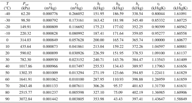
Table 3 presents a sample of the saturated HFO-1234yf data. A more complete set of tables (including the superheated region) and a computer program in the EES platform (Klein, 2010) are available from the authors upon request. In the subcooled liquid region, as
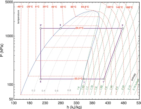
expected, the variation of the enthalpy as a function of pressure at constant temperature was insignificant (typically less than 1.1%), except near the critical point. Figures 1 and 2 show the pressure-specific enthalpy (P-h) diagrams for HFO-1234yf and HFC-134a, respectively. Lines of constant temperature and of constant entropy are shown together with the idealized refrigeration cycle between evaporating and condensing temperatures of -23.3°C and 54.4°C (the so-called checkpoint condition) for both refrigerants. In the idealized cycles shown in these figures, the internal heat exchanger effectiveness has been set equal to unity in order to magnify the most relevant differences between the fluids. These differences will be explored next in the light of the thermodynamic cycle quantities.
Table 3. Properties of HFO-1234yf at Saturation Conditions.
T
(°C)
Psat
(kPa)
vf
(m³/kg)
vg
(m³/kg)
hf
(kJ/kg)
hfg
(kJ/kg)
hg
(kJ/kg)
sf
(kJ/kgK)
sg
(kJ/kgK) -40 62.20 0.000776 0.266052 151.95 186.59 338.54 0.80044 1.61091
-30 98.50 0.000792 0.173161 163.42 181.98 345.40 0.85332 1.60725
-20 149.91 0.000809 0.116692 175.23 177.02 352.25 0.90399 1.60562
-10 220.32 0.000828 0.080992 187.41 171.64 359.05 0.95277 1.60558
0 314.03 0.000849 0.057628 200.00 165.74 365.74 1.00000 1.60677
10 435.64 0.000873 0.041861 213.04 159.22 372.26 1.04597 1.60881
20 590.02 0.000899 0.030926 226.59 151.95 378.53 1.09100 1.61137
30 782.30 0.000930 0.023152 240.71 143.76 384.47 1.13543 1.61409
40 1017.86 0.000966 0.017497 255.53 134.43 389.97 1.17963 1.61656
50 1302.35 0.001009 0.013294 271.19 123.66 394.85 1.22411 1.61829
60 1641.91 0.001062 0.010100 287.95 110.93 398.88 1.26959 1.61859
70 2043.48 0.001133 0.007611 306.26 95.37 401.63 1.31730 1.61631
80 2515.77 0.001237 0.005598 327.10 75.09 402.19 1.36985 1.60906
130 180 230 280 330 380 430 480 530 50 100 1000 5000
h (kJ/kg)
P (
k
P
a
)
-40°C -20°C 0°C 20°C 40°C 60°C 80°C
1.6 1.6
5
1.7 1.7
5
1.8 1.8
5
1.9 1.9
5
2.1 5 k
J/kg K
0.2 0.4 0.6 0.8
54.4°C -23.3°C 1 1' 2 3 3' 4
94.8°C 120°C 140°C 160°C
2.0 2.0
5 2.1 0 tem pe rat ur e
entr opy
Figure 1. P-h diagram of HFO-1234yf with an idealized vapor compression cycle at the check-point condition. The effectiveness of the internal heat exchanger is 100%.
130 180 230 280 330 380 430 480 530
50 100 1000 5000
0.2 0.4 0.6 0.8
-40°C -20°C 0°C 20°C 40°C 60°C 80°C
0.2 0.4 0.6 0.8
-40°C -20°C 0°C 20°C 40°C 60°C 80°C
0.2 0.4 0.6 0.8
-40°C -20°C 0°C 20°C 40°C 60°C 80°C
0.2 0.4 0.6 0.8
-40°C -20°C 0°C 20°C 40°C 60°C 80°C
0.2 0.4 0.6 0.8
-40°C -20°C 0°C 20°C 40°C 60°C 80°C
0.2 0.4 0.6 0.8
-40°C -20°C 0°C 20°C 40°C 60°C 80°C
0.2 0.4 0.6 0.8
-40°C -20°C 0°C 20°C 40°C 60°C 80°C
0.2 0.4 0.6 0.8
-40°C -20°C 0°C 20°C 40°C 60°C 80°C
0.2 0.4 0.6 0.8
-40°C -20°C 0°C 20°C 40°C 60°C 80°C
0.2 0.4 0.6 0.8
-40°C -20°C 0°C 20°C 40°C 60°C 80°C
0.2 0.4 0.6 0.8
-40°C -20°C 0°C 20°C 40°C 60°C 80°C
0.2 0.4 0.6 0.8
-40°C -20°C 0°C 20°C 40°C 60°C 80°C
0.2 0.4 0.6 0.8
-40°C -20°C 0°C 20°C 40°C 60°C 80°C
0.2 0.4 0.6 0.8
-40°C -20°C 0°C 20°C 40°C 60°C 80°C
0.2 0.4 0.6 0.8
-40°C -20°C 0°C 20°C 40°C 60°C 80°C
0.2 0.4 0.6 0.8
-40°C -20°C 0°C 20°C 40°C 60°C 80°C
0.2 0.4 0.6 0.8
-40°C -20°C 0°C 20°C 40°C 60°C 80°C
0.2 0.4 0.6 0.8
-40°C -20°C 0°C 20°C 40°C 60°C 80°C
0.2 0.4 0.6 0.8
-40°C -20°C 0°C 20°C 40°C 60°C 80°C
0.2 0.4 0.6 0.8
-40°C -20°C 0°C 20°C 40°C 60°C 80°C
0.2 0.4 0.6 0.8
-40°C -20°C 0°C 20°C 40°C 60°C 80°C
0.2 0.4 0.6 0.8
-40°C -20°C 0°C 20°C 40°C 60°C 80°C
0.2 0.4 0.6 0.8
-40°C -20°C 0°C 20°C 40°C 60°C 80°C
0.2 0.4 0.6 0.8
-40°C -20°C 0°C 20°C 40°C 60°C 80°C
0.2 0.4 0.6 0.8
-40°C -20°C 0°C 20°C 40°C 60°C 80°C
0.2 0.4 0.6 0.8
-40°C -20°C 0°C 20°C 40°C 60°C 80°C
0.2 0.4 0.6 0.8
-40°C -20°C 0°C 20°C 40°C 60°C 80°C
0.2 0.4 0.6 0.8
-40°C -20°C 0°C 20°C 40°C 60°C 80°C
0.2 0.4 0.6 0.8
-40°C -20°C 0°C 20°C 40°C 60°C 80°C
0.2 0.4 0.6 0.8
-40°C -20°C 0°C 20°C 40°C 60°C 80°C
0.2 0.4 0.6 0.8
-40°C -20°C 0°C 20°C 40°C 60°C 80°C
0.2 0.4 0.6 0.8
-40°C -20°C 0°C 20°C 40°C 60°C 80°C
0.2 0.4 0.6 0.8
-40°C -20°C 0°C 20°C 40°C 60°C 80°C
0.2 0.4 0.6 0.8
-40°C -20°C 0°C 20°C 40°C 60°C 80°C
0.2 0.4 0.6 0.8
-40°C -20°C 0°C 20°C 40°C 60°C 80°C
0.2 0.4 0.6 0.8
-40°C -20°C 0°C 20°C 40°C 60°C 80°C
0.2 0.4 0.6 0.8
-40°C -20°C 0°C 20°C 40°C 60°C 80°C
0.2 0.4 0.6 0.8
-40°C -20°C 0°C 20°C 40°C 60°C 80°C
0.2 0.4 0.6 0.8
-40°C -20°C 0°C 20°C 40°C 60°C 80°C
0.2 0.4 0.6 0.8
-40°C -20°C 0°C 20°C 40°C 60°C 80°C
0.2 0.4 0.6 0.8
-40°C -20°C 0°C 20°C 40°C 60°C 80°C
0.2 0.4 0.6 0.8
-40°C -20°C 0°C 20°C 40°C 60°C 80°C
0.2 0.4 0.6 0.8
-40°C -20°C 0°C 20°C 40°C 60°C 80°C
0.2 0.4 0.6 0.8
-40°C -20°C 0°C 20°C 40°C 60°C 80°C
0.2 0.4 0.6 0.8
-40°C -20°C 0°C 20°C 40°C 60°C 80°C
0.2 0.4 0.6 0.8
-40°C -20°C 0°C 20°C 40°C 60°C 80°C
0.2 0.4 0.6 0.8
-40°C -20°C 0°C 20°C 40°C 60°C 80°C
0.2 0.4 0.6 0.8
-40°C -20°C 0°C 20°C 40°C 60°C 80°C
0.2 0.4 0.6 0.8
-40°C -20°C 0°C 20°C 40°C 60°C 80°C
0.2 0.4 0.6 0.8
-40°C -20°C 0°C 20°C 40°C 60°C 80°C
0.2 0.4 0.6 0.8
-40°C -20°C 0°C 20°C 40°C 60°C 80°C
0.2 0.4 0.6 0.8
-40°C -20°C 0°C 20°C 40°C 60°C 80°C
0.2 0.4 0.6 0.8
-40°C -20°C 0°C 20°C 40°C 60°C 80°C
0.2 0.4 0.6 0.8
-40°C -20°C 0°C 20°C 40°C 60°C 80°C
0.2 0.4 0.6 0.8
-40°C -20°C 0°C 20°C 40°C 60°C 80°C
0.2 0.4 0.6 0.8
-40°C -20°C 0°C 20°C 40°C 60°C 80°C
0.2 0.4 0.6 0.8
-40°C -20°C 0°C 20°C 40°C 60°C 80°C
0.2 0.4 0.6 0.8
-40°C -20°C 0°C 20°C 40°C 60°C 80°C
0.2 0.4 0.6 0.8
-40°C -20°C 0°C 20°C 40°C 60°C 80°C
0.2 0.4 0.6 0.8
-40°C -20°C 0°C 20°C 40°C 60°C 80°C
0.2 0.4 0.6 0.8
-40°C -20°C 0°C 20°C 40°C 60°C 80°C
0.2 0.4 0.6 0.8
-40°C -20°C 0°C 20°C 40°C 60°C 80°C
0.2 0.4 0.6 0.8
-40°C -20°C 0°C 20°C 40°C 60°C 80°C
0.2 0.4 0.6 0.8
-40°C -20°C 0°C 20°C 40°C 60°C 80°C
0.2 0.4 0.6 0.8
-40°C -20°C 0°C 20°C 40°C 60°C 80°C
0.2 0.4 0.6 0.8
-40°C -20°C 0°C 20°C 40°C 60°C 80°C
0.2 0.4 0.6 0.8
-40°C -20°C 0°C 20°C 40°C 60°C 80°C
0.2 0.4 0.6 0.8
-40°C -20°C 0°C 20°C 40°C 60°C 80°C
0.2 0.4 0.6 0.8
-40°C -20°C 0°C 20°C 40°C 60°C 80°C
0.2 0.4 0.6 0.8
-40°C -20°C 0°C 20°C 40°C 60°C 80°C
0.2 0.4 0.6 0.8
-40°C -20°C 0°C 20°C 40°C 60°C 80°C
0.2 0.4 0.6 0.8
-40°C -20°C 0°C 20°C 40°C 60°C 80°C
0.2 0.4 0.6 0.8
-40°C -20°C 0°C 20°C 40°C 60°C 80°C
0.2 0.4 0.6 0.8
-40°C -20°C 0°C 20°C 40°C 60°C 80°C
0.2 0.4 0.6 0.8
-40°C -20°C 0°C 20°C 40°C 60°C 80°C
0.2 0.4 0.6 0.8
-40°C -20°C 0°C 20°C 40°C 60°C 80°C
0.2 0.4 0.6 0.8
-40°C -20°C 0°C 20°C 40°C 60°C 80°C
0.2 0.4 0.6 0.8
-40°C -20°C 0°C 20°C 40°C 60°C 80°C
0.2 0.4 0.6 0.8
-40°C -20°C 0°C 20°C 40°C 60°C 80°C
0.2 0.4 0.6 0.8
-40°C -20°C 0°C 20°C 40°C 60°C 80°C
0.2 0.4 0.6 0.8
-40°C -20°C 0°C 20°C 40°C 60°C 80°C
0.2 0.4 0.6 0.8
-40°C -20°C 0°C 20°C 40°C 60°C 80°C
0.2 0.4 0.6 0.8
-40°C -20°C 0°C 20°C 40°C 60°C 80°C
0.2 0.4 0.6 0.8
-40°C -20°C 0°C 20°C 40°C 60°C 80°C
0.2 0.4 0.6 0.8
-40°C -20°C 0°C 20°C 40°C 60°C 80°C
0.2 0.4 0.6 0.8
-40°C -20°C 0°C 20°C 40°C 60°C 80°C
0.2 0.4 0.6 0.8
-40°C -20°C 0°C 20°C 40°C 60°C 80°C
0.2 0.4 0.6 0.8
-40°C -20°C 0°C 20°C 40°C 60°C 80°C
0.2 0.4 0.6 0.8
-40°C -20°C 0°C 20°C 40°C 60°C 80°C
0.2 0.4 0.6 0.8
-40°C -20°C 0°C 20°C 40°C 60°C 80°C
0.2 0.4 0.6 0.8
-40°C -20°C 0°C 20°C 40°C 60°C 80°C
0.2 0.4 0.6 0.8
-40°C -20°C 0°C 20°C 40°C 60°C 80°C
0.2 0.4 0.6 0.8
-40°C -20°C 0°C 20°C 40°C 60°C 80°C
0.2 0.4 0.6 0.8
-40°C -20°C 0°C 20°C 40°C 60°C 80°C
0.2 0.4 0.6 0.8
-40°C -20°C 0°C 20°C 40°C 60°C 80°C
0.2 0.4 0.6 0.8
-40°C -20°C 0°C 20°C 40°C 60°C 80°C
0.2 0.4 0.6 0.8
-40°C -20°C 0°C 20°C 40°C 60°C 80°C
0.2 0.4 0.6 0.8
-40°C -20°C 0°C 20°C 40°C 60°C 80°C
0.2 0.4 0.6 0.8
-40°C -20°C 0°C 20°C 40°C 60°C 80°C
0.2 0.4 0.6 0.8
-40°C -20°C 0°C 20°C 40°C 60°C 80°C
0.2 0.4 0.6 0.8
-40°C -20°C 0°C 20°C 40°C 60°C 80°C
0.2 0.4 0.6 0.8
-40°C -20°C 0°C 20°C 40°C 60°C 80°C
0.2 0.4 0.6 0.8
-40°C -20°C 0°C 20°C 40°C 60°C 80°C
0.2 0.4 0.6 0.8
-40°C -20°C 0°C 20°C 40°C 60°C 80°C
0.2 0.4 0.6 0.8
-40°C -20°C 0°C 20°C 40°C 60°C 80°C
0.2 0.4 0.6 0.8
-40°C -20°C 0°C 20°C 40°C 60°C 80°C
0.2 0.4 0.6 0.8
-40°C -20°C 0°C 20°C 40°C 60°C 80°C
0.2 0.4 0.6 0.8
-40°C -20°C 0°C 20°C 40°C 60°C 80°C
0.2 0.4 0.6 0.8
-40°C -20°C 0°C 20°C 40°C 60°C 80°C
0.2 0.4 0.6 0.8
-40°C -20°C 0°C 20°C 40°C 60°C 80°C
0.2 0.4 0.6 0.8
-40°C -20°C 0°C 20°C 40°C 60°C 80°C
0.2 0.4 0.6 0.8
-40°C -20°C 0°C 20°C 40°C 60°C 80°C
0.2 0.4 0.6 0.8
-40°C -20°C 0°C 20°C 40°C 60°C 80°C
0.2 0.4 0.6 0.8
-40°C -20°C 0°C 20°C 40°C 60°C 80°C
0.2 0.4 0.6 0.8
-40°C -20°C 0°C 20°C 40°C 60°C 80°C
0.2 0.4 0.6 0.8
-40°C -20°C 0°C 20°C 40°C 60°C 80°C
0.2 0.4 0.6 0.8
-40°C -20°C 0°C 20°C 40°C 60°C 80°C
1 1' 2 3 3' 4 120°C 140°C 101°C 54.4°C -23.3°C
1.6 1.6
5
1.7 1.7
5
1.8 1.8
5
1.9 1.9
5
2.0 2.0
5 2.1
5
2.1 2.2
kJ/ kgK
P (
k
Pa
)
h (kJ/kg)
tem pe rat ureentr opy
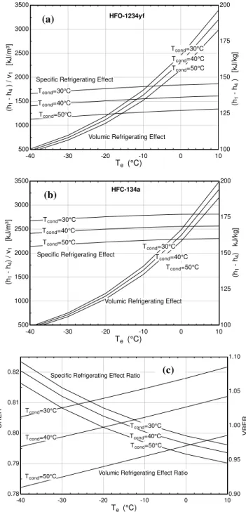
Figures 3(a) and 3(b) illustrate the behavior of the specific refrigerating effect and of the volumic refrigerating effect as a function of the evaporating and condensing pressures for HFO-1234yf and HFC-134a, respectively. The effectiveness of the internal heat exchanger was set equal to the typical value of 0.7 in all cases.
-40 -30 -20 -10 0 10
500 1000 1500 2000 2500 3000 3500
100 125 150 175 200
Te (°C)
(h1
- h
4
) /
v1
[k
J
/m³]
Tcond=40°C
Tcond=50°C
Tcond=30°C
(h1
- h
4
) [k
J
/k
g
]
Specific Refrigerating Effect
Volumic Refrigerating Effect
Tcond=40°C
Tcond=50°C
Tcond=30°C
HFO-1234yf
-40 -30 -20 -10 0 10
500 1000 1500 2000 2500 3000 3500
100 125 150 175 200
Te (°C)
(h1
- h
4
) / v
1
[k
J
/m
³]
Tcond=40°C
Tcond=50°C
Tcond=30°C
(h1
- h
4
) k
J
/k
g
]
Specific Refrigerating Effect
Volumic Refrigerating Effect Tcond=40°C
Tcond=50°C
Tcond=30°C
HFC-134a
-40 -30 -20 -10 0 10 0.78
0.79 0.80 0.81 0.82
0.90 0.95 1.00 1.05 1.10
VR
ER
Te (°C)
SRE
R
Tcond=40°C
Tcond=50°C
Tcond=30°C
Tcond=30°C
Tcond=40°C
Tcond=50°C
Volumic Refrigerating Effect Ratio Specific Refrigerating Effect Ratio
Figure 3. The specific refrigerating effect and volumic refrigerating effect for (a) HFO-1234yf and (b) HFC-134a as a function of evaporating and condensing temperatures. (c) Specific refrigerating effect and volumic refrigerating effect ratios.
For both quantities, HFC-134a exhibits higher values than HFO-1234yf, as can be observed in Fig. 3(c) which presents the ratio of the above mentioned quantities for HFO-1234yf to HFC-134a. As pointed out by Gosney (1982), the specific refrigerating effect establishes the mass flow rate of refrigerant necessary to produce a given refrigeration capacity. Thus, the larger the specific refrigerating effect, the smaller the required mass flow rate.
Alternatively, the volumic refrigerating effect establishes the swept volume rate to be achieved with a positive displacement compressor in order to provide a certain refrigeration capacity. A large volumic refrigerating effect can thus be associated with a more compact pump.
Figures 4(a) and 4(b) show the specific work of isentropic compression and volumic work of isentropic compression as a function of the evaporating and condensing pressures for HFO-1234yf and HFC134a, respectively. The ratio of both quantities as a function of the same parameters is shown in Fig. 4(c). Again, the internal heat exchanger effectiveness is set equal to 0.7.
(a)
-40 -30 -20 -10 0 10
150 200 250 300 350 400 450 500
0 10 20 30 40 50 60 70
Te (°C)
Tcond=40°C
Tcond=50°C
Tcond=30°C
(h2
- h
1'
)S
[k
J
/k
g
]
Tcond=40°C
Tcond=50°C
Tcond=30°C
(h2
- h
1'
)/ v
1'
[k
J
/m
³]
Volumic Specific Work of Isentropic Compression Specific Work of Isentropic Compression
HFO-1234yf
(a)
(b)
-40 -30 -20 -10 0 10
150 200 250 300 350 400 450 500
0 10 20 30 40 50 60 70
Te (°C)
Tcond=40°C
Tcond=50°C
Tcond=30°C
(h2
- h
1'
)S
[k
J
/k
g
]
Tcond=40°C
Tcond=50°C
Tcond=30°C
(h2
- h
1'
)/
v1'
[k
J
/m
³]
Volumic Specific Work of Isentropic Compression Specific Work of Isentropic Compression
HFC-134a
(b)
(c)
-40 -30 -20 -10 0 10 0.80
0.81 0.82 0.83
0.96 0.98 1.00 1.02 1.04 1.06 1.08 1.10
VW
IC
R
Te (°C)
SW
IC
R
Tcond=40°C
Tcond=50°C
Tcond=30°C
Tcond=30°C
Tcond=40°C
Tcond=50°C
Specific Work of Isentropic Compression Ratio Volumic Work of Isentropic Compression Ratio
(c)
Figure 4. The specific work of isentropic compression and volumic work of isentropic compression for (a) HFO-1234yf and (b) HFC-134a as a function of evaporating and condensing temperatures. (c) Specific work of isentropic compression and volumic work of isentropic compression ratios.
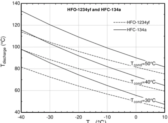
condensing temperature for both refrigerants. This quantity is larger for HFC-134a because the increase in ∂p/∂h|s with increasing
evaporating temperature is sharper for HFO-1234yf (see Figs. 1 and 2). As a result, the compressor discharge temperature will be lower for HFO-1234yf, as can be seen from Fig. 5. In fact, the values of ∂p/∂h|s for HFO-1234yf are such that in the limiting case of an
isentropic compression of an initially saturated vapor, the discharged refrigerant can exit the compressor as a two-phase mixture at the condensing pressure, as can be seen in Fig. 1. The volumic work of isentropic compression represents the mean effective pressure acting on the piston of an ideal positive displacement pump and is, therefore, related to the power which is required to drive the compressor. For both refrigerants, the trends are quite similar, but HFO-1234yf exhibits larger values of this quantity at low evaporating temperatures and slightly smaller values at high evaporating temperatures.
-40 -30 -20 -10 0 10
40 60 80 100 120 140
Te (°C)
Td
ischar
ge
(°
C)
Tcond=40°C
Tcond=50°C
Tcond=30°C
HFC-134a HFC-134a HFO-1234yf HFO-1234yf HFO-1234yf and HFC-134a
Figure 5. Compressor discharge temperature for HFO-1234yf and HFC-134a as a function of evaporating and condensing temperatures.
The behavior of the isentropic coefficient of performance (COP) is presented in Fig. 6. Again, the internal heat exchanger effectiveness is set equal to 0.7. As can be seen, HFC-134a exhibits a little but consistently higher values of COP, with a slight increasing difference between the curves with increasing condensing temperature. This is due to the higher values of specific refrigerating effect observed for HFC-134a which clearly prevails over the comparatively lower values of the specific work of isentropic compression associated with HFO-1234yf.
-40 -30 -20 -10 0 10 0
2 4 6 8 10 12 14
0.97 0.975 0.98 0.985 0.99 0.995 1 1.005
Te (°C)
Tcond=40°C Tcond=50°C
Tcond=30°C
HFO-1234yf and HFC-134a
CO
Pis
e
n
.
HFC-134a HFC-134a HFO-1234yf HFO-1234yf
Ra
ti
o
Tcond=30°C
Tcond=40°C
Tcond=50°C
Figure 6. The isentropic coefficient of performance (COP) for HFO-1234yf and HFC-134a as a function of evaporating and condensing temperatures.
The influence of the heat exchanger effectiveness on the COP is illustrated in Fig. 7, where the COP has been normalized with respect to the COP at zero effectiveness (i.e. with a 5°C superheat at the compressor inlet). The condensing temperature in Fig. 7 has been kept fixed at 50°C. The presence of an internal heat exchanger is beneficial for both refrigerants in the sense that the COP ratio is greater than unity for any value of effectiveness. This means that the effect of the increase in h1 – h4 due to the lower refrigerant quality
entering the evaporator surmounts that of the increase in (h2-h1’)s
associated with the decrease in ∂p/∂h|s with decreasing evaporating
pressure. Because ∂p/∂h|s is larger for HFO-1234yf the increase in
(h2-h1’)s with increasing compressor inlet temperature is less
pronounced than that of HFC-134a, which makes the COP of the new refrigerant larger than that of HFC-134a.
0 0.2 0.4 0.6 0.8 1
1 1.1 1.2 1.3 1.4
ε
CO
P
/C
O
P ε=
0
HFO-1234yf Te = 0°C Te = -20°C
Te = -40°C
HFC-134a Te = 0°C Te = -20°C
Te = -40°C
Figure 7. Effect of the heat exchanger effectiveness on the COP. The condensing temperature is equal to 50°C.
Conclusions
State and thermodynamic cycle property data were presented for the new refrigerant HFO-1234yf. A calculation approach based on the concept of departure functions employing the Peng and Robinson (1976) equation of state has been employed in order to determine the physical properties of the new refrigerant. The calculation procedure was validated via comparison with existing results and experimental data for HFO-1234yf and HFC-134a.
As far as the cycle properties are concerned, the following conclusions can be drawn:
1. The specific refrigeration effect and the volumic refrigeration effect are both higher for HFC-134a, which means that less mass flow per unit time is needed for a specified refrigeration capacity and thus HFO-1234yf would require a larger swept volume for a specific mass flow rate.
2. The specific work of isentropic compression is larger for HFC-134a due to its more pronounced decrease in ∂p/∂h|s with
decreasing evaporating pressure. As a result, the compressor discharge temperature becomes lower for HFO-1234yf, which seems to indicate, together with the larger mass flow rate needed for a specified refrigeration capacity, that careful attention should be paid to the compressor valve design in order to minimize the valve losses.
Tillner-Roth, R., Baehr, H.D., 1994, “An international standard formulation of the thermodynamic properties of 1,1,1,2-tetrafluoroethane (HFC-134a) for temperatures from 170 K to 455 K at pressures up to 70 MPa”, The Journal of Physical Chemistry, Vol. 23, pp. 657-729.
Acknowledgements
The authors would like to thank CNPq (Grant No. 573581/2008-8 – National Institute of Science and Technology in Refrigeration and Thermophysics) for the financial support.
Appendix
References
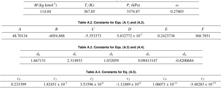
The HFO-1234yf molecular parameters and experimental data fits of vapor pressure, saturated liquid density and ideal gas heat capacity at constant pressure provided by Leck (2009) are summarized below. Table A.1 presents the molar mass, critical temperature and pressure and acentric factor of HFO-1234yf. The vapor pressure relationships are given by (Leck, 2009):
Brasz, J.J., 2009, “Variable-speed centrifugal compressor behavior with low GWP refrigerants”. In: Proceedings of the International Conference on Compressors and their Systems, Institution of Mechanical Engineers, pp. 247-256, London, UK, September 7-9.
Brown, J.S., Zilio, C., Cavallini, A., 2010 “Thermodynamic properties of eight fluorinated olefins”, International Journal of Refrigeration, Vol. 33,
pp. 235-241.
) ln( ln
ln F T
T T F E DT T C T B A
Psat ⎟ −
⎠ ⎞ ⎜ ⎝ ⎛ − + + + +
= (A.1)
Elliot, J.R., Lira, C.T., 1999, “Introductory Chemical Engineering Thermodynamics”, Prentice Hall, Upper Saddle River, NJ, 660 p.
Gosney, W.B., 1982, “Principles of Refrigeration. Cambridge
University Press”, New York, NY, 666 p.
(
)
⎥⎦⎤⎢⎣
⎡ − +
− + + − =
T T F T
F E D T C T
B dT dP P
sat 1
ln 1
2
2 (A.2)
Hankinson, R.W., Thomson, G.H., 1979, “A new correlation for saturated densities of liquids and their mixtures”, AIChE Journal, Vol. 28, pp. 653-663.
Hulse, R., Singh, R., Pham, H., 2009, “Physical properties of HFO-1234yf”. In: 3rd IIR Conference on Thermophysical Properties and Transfer Processes of Refrigerants, Paper No. IIR-178, Boulder, CO, June 23-26.
where P is in kPa and T is in K. The constants are presented in Table A.2.
The saturated liquid mass density correlation is given by (Leck, 2009):
Klein, S.A., 2010, Engineering equation solver (EES), Professional version V8.528.
Leck, T.J., 2009, “Evaluation of HFO-1234yf as a potential replacement for R-134a in refrigeration applications”. In: 3rd IIR Conference on Thermophysical Properties and Transfer Processes of Refrigerants, Paper
No. IIR-155, Boulder, CO, June 23-26.
∑
==
4 0
0 .
478 i
i i f
X d
ρ
(A.3)
Lemmon, E.W., Huber, M.L., McLinden, M.O., 2007, “REFPROP – Reference Fluid Thermodynamic and Transport Properties”, NIST Standard Reference Database 23, Version 8.0, National Institute of Science and
Technology, Boulder, CO, USA. 1 367.85 0.3315471
3 1
− ⎟ ⎠ ⎞ ⎜
⎝ ⎛ −
= T
X (A.4)
Minor, B., Spatz, M., 2008, “HFO-1234yf low GWP refrigerant update”. In: International Refrigeration and Air Conditioning Conference at
Purdue, Paper No. 2349, West Lafayette, IN, July 14-17. where ρf is in k gm
-3
and T is in K. The constants are presented in Table A.3.
Peng, D.Y., Robinson, D.B., 1976, “A new two-constant equation of state”.
Industrial and Engineering Chemistry: Fundamentals, Vol. 15, pp. 59-64. The ideal gas specific heat capacity correlation is given by (Leck, 2009):
Poling, B.E., Prausnitz, J.M., O’Connell, J.P., 2000, “The properties of gases and liquids”. Fifth Edition, McGraw-Hill, NY, 681 p.
Stoecker, W.F., Jones, J.W., 1982, “Refrigeration and air conditioning”.
Second Edition, McGraw-Hill, New York, NY, 443 p.
∑
=
=
5 0
i i i ig
P cT
c (A.5)
Tanaka, K., Higashi, Y., 2009, “Thermodynamic properties of HFO-1234yf (2,3,3,3-tetrafluoropropene)”. In: 3rd IIR Conference on Thermophysical Properties and Transfer Processes of Refrigerants, Paper
No. IIR-136, Boulder, CO, June 23-26. where is in kJ kg
ig P
c -1 K-1 and T is in K. The constants are presented
in Table A.4.
Table A.1. HFO-1234yf properties.
M (kg kmol-1) Tc(K) Pc (kPa) ω
114.04 367.85 3374.87 0.27803
Table A.2. Constants for Eqs. (A.1) and (A.2).
A B C D E F
48.70134 -4054.888 -5.353373 5.632772 x 10⁻³ 0.2423738 368.7851
Table A.3. Constants for Eqs. (A.3) and (A.4).
d0 d1 d2 d3 d4
1.667131 2.314933 1.032059 0.09413147 -0.8200684
Table A.4. Constants for Eq. (A.5).
c0 c1 c2 c3 c4 c5