The dynamic response and energy absorption capabilities of clamped shallow sandwich arches with aluminum foam core were numerically investigated by impacting the arches at mid span with metallic foam projectiles. The typical deformation modes, deflec tion response, and core compression of sandwich arches obtained from the tests were used to validate the computation model. The resistance to impact loading was quantified by the permanent transverse deflection at mid span of the arches as a function of projectile momentum. The sandwich arches have a higher shock resistance than the monolithic arches of equal mass, and shock resistance could be significantly enhanced by optimizing geomet rical configurations. Meanwhile, decreasing the face sheet thickness and curvature radius could enhance the energy absorption capabil ity of the sandwich arches. Finite element calculations indicated that the ratio of loading time to structural response time ranged from 0.1 to 0.4. The projectile momentum, which was solely used to quantify the structural response of sandwich arches, was insuf ficient. These findings could provide guidance in conducting fur ther theoretical studies and producing the optimal design of metal lic sandwich structures subjected to impact loading.
sandwich arch; metallic foam; dynamic response; energy absorp tion; optimization design
! " #$% #"
The superior performance of sandwich structures relative to monolithic solid structures is well es tablished for the broad range of application requiring high quasi static strength and stiffness (Lu and Yu, 2003; Ashby et al., 2000; Zhu et al., 2010). However, the resistance of sandwich structures to impact loading must be fully investigated to quantify the advantage of sandwich designs over the monolithic design for potential application in shock resistant structures.
& ' ( ) *
) + , )
a e Institute of Applied Mechanics and
Biomedical Engineering, Taiyuan University of Technology, 030024, China
c Institute of Applied Mechanics and
Biomedical Engineering, Taiyuan University of Technology, 030024, China Corresponding Author:
http://dx.doi.org/10.1590/1679 78251860
Considerable research demonstrates that the sandwich beams and plates outperform the correspond ing monolithic structures for shock loading. The typical deformation/failure modes, the dynamic response, and the failure mechanism of sandwich beams and panels have been obtained experimen tally (Rubino et al., 2008; Wang et al., 2011; Zhu et al., 2008). Corresponding theoretical and nu merical predictions have also been completed (Fleck et al., 2004; Qiu et al., 2004; Zhu et al., 2010; Hutchinson et al., 2005). The superior performance of sandwich structures ¬is caused by a segment of the fluid–structure interaction (Liang et al., 2007) and by the greater bending strength of sand wich configures when compared with their monolithic counterpart. All these works, however, are restricted to the flat sandwich structures, although substantive curved structures are applied in practical engineering.
Corona E and Wang JW (2008) experimented on arches constructed by bonding a layer of foam to a single metal sheet under a point load at mid span. Results showed that the critical buckling loads of such arches could be significantly increased with the presence of the foam layer. Karam and Gibson (2008) and Obrecht et al. (1995) also indicated that shells supported or coated with light weight materials display less imperfection sensitivity than the regular monolithic shells do.
Shen et al. (2010, 2013) investigated the response of curved sandwich panels and short sandwich tubes with aluminum foam cores under air blast loading. Fatt et al.(2012) developed an analytical model to predict the early time response of a composite cylindrical sandwich shell under blasting loading. More recently, Jing et al.(2013) experimentally and numerically investigated the effects of geometrical configurations and loading impulse on the deformation/failure of cylindrical sandwich shells with aluminum foam cores under air blast and projectile impact loadings over a wide range of velocities. To qualitatively and quantitatively evaluate the superior resistance of sandwich structure to shock loading, Randford et al.(2005) introduced an experimental technique, in which structures were subjected to high intensity pressure pulses by using metallic foam projectiles. The applied pressure versus time pulse can be adjusted to a prescribed dynamic loading history by changing the velocity, length, and density of the foam projectile. Xie et al. (2013) experimentally examined the dynamic responses of clamped sandwich arches with various geometrical configurations by using the foam projectile loading technique. The effects of initial projectile momentum, face sheet thickness, core thickness, and radius of curvature on the structural response were obtained. However, the cross coupling between the dynamic response of the structures and that of the projectile was not analyzed. Thus, quantifying the enhanced shock resistance of the sandwich arches was difficult.
- .( . ." $.
A total of 19 shallow sandwich arch specimens consisting of two thin aluminum alloy face sheets and an aluminum core, with a span of 320 mm and width of 60 mm, were tested (see Fig. 1). Two radii of curvature R (300 and 600 mm), three face sheet thicknesses (0.5, 0.8, and 1.0 mm), and core thicknesses (10, 20, and 30 mm) were utilized. Impact tests were conducted on a gas gun device by using a specially designed fixture to clamp the sandwich arches (Xie et al., 2013). An improved loading technique, which can perfectly provide the pressure versus time pulse of shock loading (Radford et al., 2005), was used to explore the dynamic response and deformation mechanisms of the sandwich arches by using metallic foam projectile. The face sheets in this study were generated from Al 2024 aluminum alloy. The mechanical properties of the face sheets are listed in Table 1. The Alporas aluminum foam cores and cylindrical projectiles with a length of 45 mm and a diame ter of 36 mm were electro discharge machined from the foam blocks of density ρp within the range of 317 kgm−3 to 356 kgm−3. The material properties of the foam cores and the projectiles provided by the supplier are shown in Table 2.
Geometry and loading configuration for a shallow clamped sandwich arch.
Density (kgm 3) Young’s Modulus (GPa) Shear Modulus (GPa) Poisson’s Ratio Yield Strength (MPa)
2700 72.4 28 0.33 75.8
! " The mechanical properties of Al 2024 aluminum alloy.
Composition (%) Density (kgm 3) Young’s Modulus (GPa) Shear Modulus (GPa) Shear Strength (MPa) Al+1.5%Ca+1.5%Ti 320±20 1.1±0.1 0.33±0.02 1.2±0.05 Tensile Strength
(MPa)
Yield Strength (MPa)
Bending Strength
(MPa) Compressive Peak Stress (MPa)
1.6±0.2 1.5±0.1 2.8±0.3 1.9±0.3
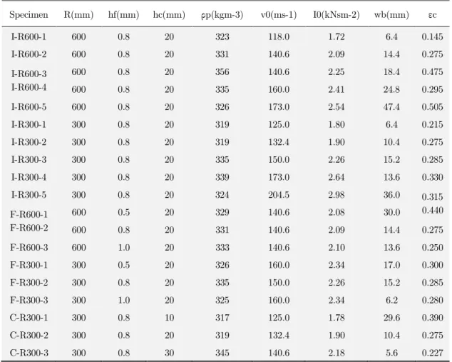
Table 3 summarizes all the experiments performed on the sandwich arches. The results of the quan titative test include the exerted impulse magnitude, the compression strain, and the permanent deflection of the back face sheet at mid span. The deformation and failure modes of the shallow sandwich arches from the tested results can be characterized by indentation or penetration of the front face sheet, progressive compression and shear failure of the core, large inelastic deformation of the back face sheets, and interfacial failure (debond at the interface) between the back face sheets and the core, which is usually accompanied by core shear failure. Some typical deformation modes were presented and compared with those of simulation results in Section 4.1.2.
Specimen R(mm) hf(mm) hc(mm) ρp(kgm 3) v0(ms 1) I0(kNsm 2) wb(mm) εc
I R600 1 600 0.8 20 323 118.0 1.72 6.4 0.145
I R600 2 600 0.8 20 331 140.6 2.09 14.4 0.275
I R600 3 I R600 4
600 0.8 20 356 140.6 2.25 18.4 0.475
600 0.8 20 335 160.0 2.41 24.8 0.295
I R600 5 600 0.8 20 326 173.0 2.54 47.4 0.505
I R300 1 300 0.8 20 319 125.0 1.80 6.4 0.215
I R300 2 300 0.8 20 319 132.4 1.90 10.4 0.275
I R300 3 300 0.8 20 335 150.0 2.26 15.2 0.285
I R300 4 300 0.8 20 339 173.0 2.64 13.6 0.330
I R300 5 300 0.8 20 324 204.5 2.98 36.0 0.315
0.440 F R600 1
F R600 2
600 0.5 20 329 140.6 2.08 30.0
600 0.8 20 331 140.6 2.09 14.4 0.275
F R600 3 600 1.0 20 333 140.6 2.10 13.6 0.250
F R300 1 300 0.5 20 326 160.0 2.34 17.0 0.300
F R300 2 300 0.8 20 335 150.0 2.26 15.2 0.285
F R300 3 300 1.0 20 325 160.0 2.34 6.2 0.280
C R300 1 300 0.8 10 317 125.0 1.78 29.6 0.390
C R300 2 300 0.8 20 319 132.4 1.90 10.4 0.275
C R300 3 300 0.8 30 345 140.6 2.18 5.6 0.227
! " Specifications of the sandwich arches and corresponding experimental results.
/ " . . . ." #$.
ratio of 2:1 (axial to transverse), resulting in an appropriate aspect ratio at complete densification stage to validate the computation convergence. The monolithic arches of equal mass were also mod eled by the default solid element. The foam projectiles were meshed with hexahedron solid element with 8 nodes.
The mechanical properties of AL 2024 aluminum alloy were simulated by a plastic kinematic constitutive model (*MAT_PLASTIC_KINEMATIC), which can account for the strain rate effect by using the Cowper–Symonds model, that is,
+
=
ε
σ
σ
ɺ (1)where and are the dynamic and static yield stresses, respectively; is the strain rate; and C and P are constant values. The effect was ignored in this simulation because the weak strain rate was sen sitive to aluminum alloy. The aluminum foam core was modeled by the material model (MAT_CRUSHALBE_FOAM), which models crushable foam with optional damping and tension cutoff. The stress and strain curve of aluminum foam used in simulation was shown in Fig.2. The model “MAT_HONEYCOMB” was used to describe the large deformation of metallic foam projec tile. This model can properly avoid the computational difficulties caused by mesh distortion in large inelastic deformation analysis. The projectile was imparted at the onset of the simulation with a uniform initial velocity. The projectile was then brought into contact with the arch at its mid span. The plastic Poisson ratios of all metallic foams were set to zero.
Stress strain curve and energy absorption efficiency strain curves of aluminum foam.
single surface contact was used for aluminum was defined between the foam cores and bot jectile and sandwich arch. The friction coeffi for the hourglass control.
0 % #" . % "$ $ % #"
The simulated results of the sandwich arches parts. The FE calculations in the first part w the reliability and validation of the former i permanent deflections of back face sheets, a resistance of the sandwich arches with diffe given mass to impact loadings were demon divided into the following aspects: (1) struct and back face sheets, (3) energy absorption c by the foam projectiles. These aspects are ind
01! 2 .
01!1! . 3
Finite element analysis has a basic criterion model. This criterion guarantees the energy c energy history curve, including the kinetic, denote that the total energy remains unchan approximately equal to 1 during the entire d es zero strain and stress, is a non physical z ness but contains grids that generate serrat can lead to errors in the calculation results. putted to avoid the occurrence of the hourg total energy. This value satisfies the general
The energ
minum foam core. The automatic surface to surface contac d both the front and back faces, as well as between the pr coefficient is defined as 0.2 and the default value is adopte
#"
arches under projectile impact loading are classified into tw part were used to compare the experimental results to verif rmer in terms of energy balance, deformation/failure modes eets, and core compression of sandwich arches. The impac h different configurations and of the monolithic arches wit emonstrated in the second part. The simulated results ar structural response process, (2) velocity response of the fron ption capability, and (4) pressure versus time history exerte are individually described in the subsequent sub sections.
terion in verifying the reliability of the numerical simulatio ergy conservation of the entire system. Fig. 3 shows a typica netic, internal, total, and hourglass energies. Figs. 3 and nchanged and the energy ratio (total energy/initial energy) i
tire deformation process. The hourglass mode, which produ sical zero energy deformation mode. This mode has no stif serrated deformation. The emergence of the hourglass mod sults. Thus, the system of the hourglass energy must be ou hourglass mode. The hourglass energy is less than 3% of th neral criterion of the numerical simulation.
e energy time histories curves of system.
contact he pro dopted to two o verify modes, impact es with lts are e front exerted
# The energy ratio
01!1- $ 4 +
Experimental results showed that the deformation/ impact loading is sensitive to the structural config Several typical deformation modes in the experim terms of face sheets and core and were compared shows the typical indentation deformation in the m tion is characterized by severe localized deformati central region of sandwich arches and is analogou (Ashaby et al., 2000; Wang et al., 2011). The depth the loading intensity and ductility of the face sheet the peripheral region of the impact location. Some the front face sheet. This condition often occurs in shown in Fig. 5a.
The aluminum foam core demonstrated two m compressive deformation and shear failure, as show mainly occurred at the loading region and in the v dent partial core compression was observed. The loading area that is usually accompanied by the in sheet with the increase of the projectile momentum face sheet mainly appears as a typically large ine occurred at the mid span of back sheet of the shallo
y ratio time histories of system .
ation/failure of sandwich arches subjected to projectile configuration and pressure pulse history of the arches. experimental results were presented and discussed in ared with those in the FE calculation results. Fig. 5a the mid span of front face sheet. This typical indenta ormation without rupture that generally occurs at the alogous to the behavior of sandwich beams and plates depth and size of the indentation primarily depend on sheet. A large and whole deformation was observed in Some of the specimens exhibited a wrinkling failure on urs in the peripheral region of the projectile loading, as
two major deformation patterns, namely, progressive s shown in Fig. 5b. The core compressive deformation the vicinity of the projectile impact, in which an evi The core shear can occur in the edges of the central the interfacial failure between the core and back face
(a) Indentation deformation of the front face sheet (I R300 4).
(b) Deformation\failure mode of the aluminum foam core F R300 1 .
(c) Large inelastic deformation of the back face sheet (C R300 1).
01!1/ $ 3 5 6
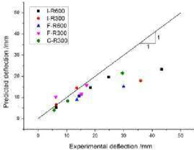
Sandwich structures are generally used in practical engineering applications because people or ob jects shielded from impact attacks are on the back side of protective structure. The mid span per manent deflection of the back face sheet of sandwich structures is normally used in assessing the resistance of an object to blast/impact loading. The experimental results showed that the back face sheet mid span deflection of sandwich specimens increases with the increase of impulse magnitude and decreases with the increase of face sheet or core thickness (Wang et al., 2011; Zhu et al., 2008; Xie et al., 2013). The experimental and simulation results were compared in terms of the permanent deflection of the central point of the back face sheets, as shown in Fig. 6. The comparative results revealed that numerical simulation predicts the permanent deflection to reasonable accuracy under low velocity impact. However, such simulation slightly under predicts the deflections when the pro jectile of momentum is relatively larger. This condition may be caused by the core layer trend in the shear failure and the interface debonding between the core and back face sheet that result in the loss of load carrying capability of shallow sandwich arches.
The typical numerical and experimental mid span deflection time curves were compared to fur ther validate the numerical model and comprehend the deformation process of the back face sheet, as shown in Fig. 7. The deflections versus time histories indicate that numerical simulation result agrees with the experimental results. Specifically, only slightly elastic vibration occurred after the peak deflection has been attained. This finding illustrates the validity of the numerical model. The permanent deflections in the FE calculations were estimated by averaging the displacements over half a cycle of the elastic vibrations (from trough to peak) immediately after the initial peak dis placement.
Fig. 8 shows that the FE predictions of the final core compression strain along with the experi mental measurements results. The FE simulation predictions conform to the experimental predic tions. However, some differences were observed in a few specimens. These differences may be caused by the use of natural topology heterogeneity and density inhomogeneous of aluminum foam in the experiment. Such substances are considered the continuous and uniform material in the finite ele ment analysis.
(a)R=600mm (b)R=300mm
$ Comparison of measured and predicted back face deflection histories at the mid point (a) R=600mm (b) R=300mm.
Comparison of the experimental and numerically predicted compression strain.
01- $ + 7 8
The preceding section stressed that the numerical simulation results conform to the experimental results. Impact resistance can be enhanced by increasing the face sheet or core thickness of sand wich structures for a given mass. However, the method that is more effective to be used is yet to be disclosed. Thus, searching for this specific method is one of the main focuses encountered in the optional design of the impact resistance ability of the sandwich structures.
and the core thickness is changed (Fig. 9 indicates these thicknesses by dashed lines). These two thicknesses were comparatively studied in three different levels of impact loading ( are 0.0205, 0.0287, and 0.0369).
The non dimension variables of the sandwich arch are as follows:
=
=
=
=
(2)
ρ
ρ
+
=
=
(3)
ρ
σ
=
(4)where R and 2L are the radius of the curvature and the actual span of the arch, respectively; and and are the yield stress and the density of face sheet, respectively. is the relative density of the core, and is the mass per unit area of the sandwich arch. Figs. 9(a) and (b) demonstrate that the influence of the change in core thickness on the impact resistance is slightly evident than that of the change in face sheet thickness in the case of changing the equal mass. Specifically, the effect of re ducing the face sheet thickness is more apparent if the specific mass of the sandwich arch is reduced. In this event, the sandwich arch must have the ability to resist impact. The effect of increasing core thickness is better if the impact resistance of the sandwich arch increased with a smaller mass of sandwich arch. However, thinner face sheets can evidently improve the energy absorption capability of sandwich arches. However, this condition easily leads to the microbuckling or penetration failure of the front face sheet, decreasing its resistance to impact loading [18, 22] (Jing et al., 2013; Xie et al., 2013).
The FE calculation was used to determine the impact resistance of a sandwich arch with differ ent configurations of given mass. A monolithic arch of equal mass was used for comparison purposes. The sandwich and monolithic arches were provided with the same mass per unit area, that is,
+
ρ
=
(5)(a) = (b) =
% Normalized permanent back face deflection versus normalized mass per area for three impulses (a) = (b) =
Specimen No. Core thickness(mm) Face sheet thickness(mm)
1 10 1.4250
2 15 1.2125
3 20 1.0000
4 25 0.7875
5 30 0.5750
! " # The configurations of the sandwich arches of the equal mass.
(a) = (b) =
01-1! + +
This section mainly focuses on two parts, namely, the process of the global structural deformation and the process of core compression. The response processes of the sandwich arches with different configurations and the monolithic arches with equal mass were examined under the same projectile velocity (140 m/s) considering that structural configurations may greatly influence the response process.
The middle plane deflections of the nodes along the circumferential direction (equally divided into nine parts from the center of the arch to the fixed end) are shown in Figs. 11 and 12. These figures reveal that the coordinates of the y axis decrease with time (corresponding to ¬the increase of deflection) and with the response process from the center to the clamped end. Figs. 11 and 12 also denote that the plastic hinge first appears in the center and then travels toward the clamped edge region during deformation. The travelling plastic hinges of the specimen, whose core is thinner or whose radius of curvature is small, are more evident than those of their corresponding counter part. The transient deflections of the nodes in the central area of the sandwich arches are conspicu ously greater than those of the permanent deflections.
The history of the core compression strain can be obtained by calculating the displacement his tory of the front and back face sheets. The histories of compression strain of the sandwich arches with different configurations (the core and face sheet thicknesses of specimens are shown in Table 4) were compared under the same velocity (v0 = 140 m/s), as illustrated in Fig. 13(a). The maximum compressive strain of the core decreases with the increase of core thickness. The core compressive strain histories from the sandwich arches with the same configuration ( =20 mm, = 1.0 mm) under different impact velocities are shown in Fig. 13(b). The change rate of the compressive strain in creases with the increase of impact velocity.
The following conclusions are drawn from the results presented above. 1) The response time at which the compressive strain attains the maximum value is related to the configuration of sandwich arches and is irrelevant to the structural curvature and the specified impact velocity; 2) the change rate of the compressive strain is related to the configuration of sandwich arches and the impact velocity; and 3) the core compression occurs in a more shorter time than the structural response time and has a negligible effect on the overall structural response of the sandwich arches.
(c) hc=20mm (d) hc=30mm
Sketches of deformation process of the sandwich arches and the monolithic arch of equal mass (R=600mm).
(a) The monolithic arch (b) hc=10mm
(c) hc=20mm (d) hc=30mm
(a) For the different core thicknesses (b) For the different impact velocities Compressive strain time history at the mid span of the sandwich arches for the different core thicknesses; (b) for the different impact velocities.
01-1- 2 3 5 6
The velocity versus time curves of the front and back face sheets of sandwich arches with different configurations under the same impact loading (projectile velocity v0 = 140 m/s) are shown in Figs. 14 and 15. The velocity of the front face sheets rapidly increases at the initial stage of response, quickly attains the maximum value, and gradually decelerates because of core compression. The velocity of the back face sheet is zero in the early stage, begins to accelerate afterwards, and achieves equal velocity when t = teq. The velocity of the front face sheet is greater than that of the back face sheet before their velocities (t < teq) become equal and the core is in compression. The core compression stops and the compression attains the maximum value when the velocities of the front and back face sheets are equal (t = teq). The sandwich arch subsequently moves together at equal velocity until they are brought to rest. The overall response process of the structure mainly occurs at this stage. The time used by the core compression is provided in Figs. 14 and 15. The core compression time teq of sandwich arches with three different configurations ranged from 0.13 ms to 0.26 ms. The achieved time teq of the common velocity are closely related to the geometrical con figuration of the specimens.
(b)
(c)
# Mid span front and back face sheet velocity versus time histories (R=600mm). (a) hc=10mm; (b) hc=20mm; (c) hc=30mm.
(a)
(c)
Mid span front and back face sheet velocity versus time histories (R=300mm). (a) hc=10mm; (b) hc=20mm; (c) hc=30mm.
01-1/ .
Metallic sandwich structures with aluminum foam core can dissipate considerable energy by large plastic deformation under blast/impact loading. The sandwich arches with different configurations at the same velocity of 140 m/s were studied and discussed to clarify the energy dissipation mecha nism of sandwich arches (Fig. 16).
From the energy absorption ratio of each part, the aluminum foam core layer is the main ener gy absorbing component exceeding more than 60% of the total energy absorption, whereas the ener gy absorbing ratio of the front and back face sheets are usually less than 20%. The energy absorbed by the front face sheet is more than that of the back face sheet when the core is relatively thinner. However, the difference of the energy absorbed by the face sheets is gradually reduced with the increase of the core thickness. The sandwich arches with a smaller radius of curvature slightly ab sorb more energy for a given projectile velocity and geometrical configuration. Meanwhile, the in crease of energy dissipation for sandwich arches with smaller curvature is absorbed by face sheets. Conducting further systematical study regarding this matter is valuable. The thinner face sheet can evidently improve the energy absorption capability of sandwich arches with equal mass. However, such improvement can lead to the penetration failure of face sheet and core shear as a result of the weak resistance to impact loading.
(a) R=600mm (b) R=300mm
01-10 + 2 + 9 .:
Metallic foam projectiles were developed to generate pressure time histories representing impulsive loading in water or air (Liang et al., 2007; Radford et al., 2005). The magnitude and duration of the pressure pulse exerted by the foam projectiles on a structure depend on the density, length, com pressive stress versus strain response of the foam, and projectile velocity. This experimental tech nology can provide a safe and effective method of studying the dynamic response and defor mation/failure modes of structure in a laboratory environment. However, the pressure time history is sensitive to the response of the target structure. Therefore, judging the results from the natural resistance property or the different pressure time history of the sandwich arches is unclear for a given momentum . Hence, explaining and clarifying this problem is necessary.
The analysis of Radford (2005) concludes that the magnitude and duration of the pressure pulse impacting a free but rigid stationary target are written as follows:
σ
ρ
ε
=
+
(6)
τ
=
ε
(7)where σpl, ρp, , and are the yield strength, density, length, and densification strain of the foam projectile, respectively. is the impact velocity.
The pressure time histories that the foam projectiles applied to the sandwich arches with the same configurations and different radius of curvature (R = 300, 600 mm) at different impact veloci ties are shown in Fig. 17. The figure denotes that the pressure time histories of the sandwich arches are identical in the same velocity and are irrelevant to their radius of curvature. A greater velocity of the projectiles equates to greater pressure of the pulse and shorter duration.
The pressure time histories that the foam projectiles imparted on the sandwich arches and the monolithic arch with equal mass in the same impact velocity ( = 140 m/s) are shown in Fig. 18. The core thicknesses of the sandwich arches are 10, 20, and 30 mm, respectively, and their corre sponding panel thicknesses are shown in Table 4. The differences between the pressure time histo ries are small, confirming that the differences in the structural response of the various sandwich and monolithic arches for a given are caused by their intrinsic impact resistance ability.
The pressure time histories can be derived from the finite element calculation. The impulse can be obtained by using the following formula:
=
∫
∞( )
(8)The ratio of the pressure duration and the structural response time T is an important indicator in evaluating whether a load can be considered the dynamic loading. The loading in the limit is im pulsive (Jones, 1989; Xue et al., 2003). The ratio was determined by using the FE calculations to quantify the level, in which the loading imposed in the arches may be approximately considered the dynamic loading. The structural response time T in this simulation is the time, at which the struc ture achieves its maximum back face sheet deflections. The duration of pulse is estimated as the time, at which 95% of the initial momentum of the foam projectile is transmitted into the structure.
∫
τ( )
=
(9)The structural response times T of the sandwich arches with different configurations and the mono lithic arch of the equal mass obtained from the finite element calculations are within the range of 1 ms to 3 ms, whereas the loading time is between 0.2 and 0.4 ms. The ratio of the pressure pulse and structural response time is . Therefore, the loading may not be considered impulsive because mo mentum was used in this study. Foam projectiles are a convenient laboratory device for evaluating and analyzing the structural response of such sandwich structure.
$ The predicted pressure time histories of the foam projectiles at three selected impact velocities (hc=20mm,hf=1.0mm)
(a) (b)
% The ratio of impulse I to momentum I0 versus core thickness.
; #" %$ "7 .
The dynamic response and energy absorption capabilities of clamped shallow sandwich arches with aluminum foam core subjected to projectile impact loading were numerically investigated. The per manent deflections and core compression of the sandwich arches were measured as a function of projectile momentum, deformation/failure modes, and structural response were compared with pre vious experimental results. The numerical simulation predicted the corresponding results to reason able accuracy, verifying the reasonability of the numerical model. The impact resistances of the sandwich arches with different configurations and a monolithic arch of equal mass were also com pared and analyzed. The sandwich arches outperformed the monolithic arches with equal mass in the range of the studied projectile momentum. An increase in the core thickness (while keeping the common area mass) could evidently enhance the shock resistance of the sandwich arches.
The finite element calculations also revealed that the pressure versus time histories imparted on the clamped monolithic arches was similar to that imparted on the sandwich arches for the studied projectile momentum. This finding confirms that the differences in the observed responses of the monolithic and sandwich arches for a given mass are affected by the intrinsic impact resistances of these structures, suggesting that the metal foam projectile is a convenient experimental tool for ranking the shock resistance of competing structures.
5
This work is supported by the National Natural Science Foundation of China (Grant Nos.11172196), Shanxi Scholarship Council of China (2013 046) and the Top Young Academic Leaders of Shanxi and the Outstanding Innovative Teams of Higher Learning Institutions of Shanxi. The financial contributions are gratefully acknowledged.
Ashby MF, Evans A, Fleck NA, Gibson LJ, Hutchinson JW, Wadley HNG, editors. Metal foams: a design guide. London: Butterworth Heinmann ; 2000.
Fatt M S H, Surabhi H. Blast Resistance and Energy Absorption of Foam Core Cylindrical Sandwich Shells under External Blast. Composite Structures, 2012; 94: 3174 3185.
Fleck N A, Deshpande V S. The resistance of clamped sandwich beams to shock loading. Journal of Applied Mechan ics, ASME 2004, 71:1 16.
Hutchinson J W, Xue Z. Metal sandwich plates optimized for pressure impulses. Int. J. of Mechanical Sciences 2005; 47:545 569.
Jing L, Wang Z H, Zhao L M, Shim V P W. Dynamic response of cylindrical sandwich shells with metallic foam cores under blast loading—Experimental investigations. (Submitted for publication)
Jing L, Wang Z H, Zhao L M. Dynamic response of cylindrical sandwich shells with metallic foam cores under blast loading—Numerical simulations. Composite Structures 2013; 99:213 23.
Jing L, Xi C Q, Wang Z H, Zhao L M. Energy absorption and failure mechanism of metallic cylindrical sandwich shells under impact loading. Materials and Design. 2013; 52: 470 480.
Jones N. Structural Impact. Cambridge University Press. 1989.
Karam G N, Gibson L J. Elastic buckling of cylindrical shells with elastic cores I Analysis. International Journal of Solids and Structures 1995; 32: 1259 1283.
Liang Y, Spuskanyuk A V, et al. The response of metallic sandwich panels to water blast. Journal of Applied Me chanics. 2007; 74:81 99.
Lu G, Yu T X. Energy absorption of structures and materials. Cambridge: Woodhead Publishing Ltd.; 2003.
Rubino V, Deshpande V S, Fleck N A. The dynamic response of end clamped sandwich beams with a Y frame or corrugated core. Int. J. Impact Eng. 2008, 35: 829 844.
Obrecht H, Fuchs p, Reinicke U, Rosenthal B, Walkowiak M. Influence of wall constructions on the load carrying capability of light weight structures. International Journal of Solids and Structures 2008; 45: 1513 1535.
Qiu X, Deshpande V S, Fleck N A. Dynamic response of a clamped circular sandwich plate subject to shock loading. Journal of Applied Mechanics, ASME. 2004, 71:637 645.
Radford D D, Deshpande V S, Fleck N A. The use of metal foam projectiles to simulate shock loading on a structure. International Journal of Impact Engineering, 2005, 31: 1152 1171.
Shen Jianhu, Lu Guoxing, Wang Zhihua, Zhao Longmao. Experiments on curved sandwich panels under blast load ing. International Journal of Impact Engineering 2010; 37: 960 970.
Shen J H, Lu G, Zhao L M, Zhang Q M. Short sandwich tubes subjected to internal explosive loading. Engineering Structures. 2013; 55: 56 65.
Wang Z H, Jing L, Ning J G, Zhao L M. The structural response of clamped sandwich beams subjected to impact loading. Composite Structures 2011; 93: 1300 1308.
Xie Q H, Jing L, Wang Z H, Zhao LM. Deformation and failure of clamped shallow sandwich arches with foam core subjected to projectile impact. Composites: Part B. 2013; 44: 330 338.
Xue Z, Hutchinson J W. Preliminary assessment of sandwich plates subject to blast loads. Int. J. Mech. Sci. 2003, 45; 687 705.
Zhu F, Lu G, Ruan D, Wang ZH. Plastic deformation, failure and energy absorption of sandwich structures with metallic cellular cores. Int. J. of Protective Structures. 2010, 1(4): 507 541.
Zhu F, Wang Z H, Lu G, Nurick G. Some theoretical considerations on the dynamic response of sandwich structures under impulsive loading. Int. J. Impact Eng. 2010; 37: 625 637.