EXPERIMENTAL INVESTIGATIONS OF
SURFACE ROUGHNESS ON OFHC
COPPER BY DIAMOND TURNING
MACHINE
K.A.MAHAJAN
Department of Mechanical Engineering
Modern Education Society’s College of Engineering, Pune-411001, Maharashtra, India DR. M. SADAIAH
Department of Mechanical Engineering,
Dr. Babasaheb Ambedkar Technology University, Lonere, Raigad -402103, Maharashtra, India S. H. GAWANDE
Department of Mechanical Engineering
Modern Education Society’s College of Engineering, Pune-411001, Maharashtra, India Abstract:
Diamond turning enables to control the process parameters accurately and to generate geometry of the component to a very high level of accuracy. In this research, a series of face cutting experiments were carried out on Oxygen Free High Conductivity Copper (OFHC). A sharp edge, single point uncontrolled waviness tool was used for machining. Quantitative effect of four process parameters, namely spindle speed, feed, depth of cut and tool nose radius on the surface roughness of copper was determined. From experimental investigations, it is found that the tool nose radius is very dominating parameter amongst the all considered parameters. It is found that as bigger tool nose radius is used, the surface roughness is improves drastically, as 5.8 nm has been achieved with higher depth, high speed and high feed.
Keywords: Diamond turning; Surface Roughness; Oxygen Free High Conductivity Copper (OFHC). 1. Introduction
Development of machining technologies over the past 40 or 50 years has attended a state of the art as in [1] which the geometrical precision of work pieces both in shape and surface roughness. Diamond turning is a well-established process, which is used in manufacturing of high precision optical component with surface roughness of few nanometers. It has been improved to an ultra machining technology for mass production of precision part of ductile materials. It includes computer hard disk substrates, print drums, polygon mirrors, form ophthalmic lenses to military components and from metallic mirrors to infrared camera lenses as stated in [1, 2]. Recent efforts extended diamond turning to brittle material like glass, germanium, silicon and even ceramics. It was done by utilizing “ductile-regime” cutting mode through decreasing depth of cut smaller than certain critical value [1, 2].
This paper tries to investigate effect of various cutting parameters as spindle speed, feed, depth of cut and tool nose radius on the surface finish by performing extensive experimentation. The experiments were performed on OFHC Copper as substrate material .The surface finish was measured on Form Taly Surf (FTS) and was found to be in nanometers. In this experiment a single point mono-crystalline diamond tool was used for cutting. The paper is organized as, section 2 gives of details of Diamond Turning Machining, performed experimentation is explained in section 3, details of results and discussion is stated in section 4, section 5 is concluding remark.
2. Diamond Turning Machining
commercial alternative to grinding, lapping or polishing which were the traditionally available solutions. Diamond turning not only enables controlling the process parameters accurately and generating geometry of the component to very high level of accuracy but also increases the level of production [3].
The special design and construction features of the machine enable to machine components to very high level of accuracy. The diamond-turning machine consists of vibration isolators to overcome external vibrations on the component. Liquid cooled aerostatic bearing mounted directly on DC motor have less than 25 nm axial and radial spindle motion accuracy. Liquid cooling reduces the thermal growth of spindle. The temperature surrounding spindle motor is maintained at 10-180C.T-shaped table mounted on hydrostatic bearing for reducing compounded error. Vacuum chuck provides uniform pressure distribution on the fixture without any small amount of distortion. Machine consists of ON-MACHINE tool measurement system to increase the tool-offset measurement [4]. Diamond turning machine is placed in CLASS 10000 room.
Diamond turning machine consists of special sharp cutting tool on high stiffness tool post. Diamond tool are either mono crystalline or poly crystalline. Single crystal diamond tool is considered as ideal tool material in ultra precision and nano-metric cutting. It consists of highest hardness, better chemical stability, better resistance to wear and the sharpened cutting edge [5].
3. Experimentation
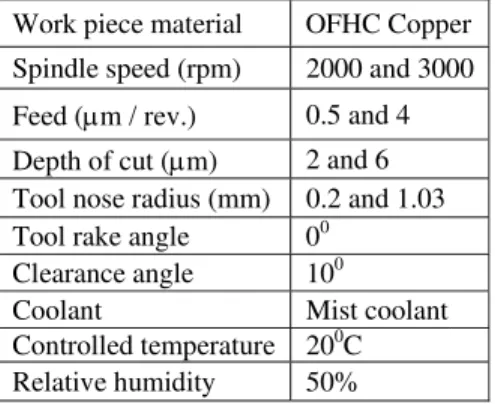
In this section detail experimentation is explained for various cutting parameters .The data required for this experiment was found from extensive pilot experimentation. The cutting parameters like Speed, Feed, Depth of Cut and Tool Nose Radius are main sources that affect the surface finish in micromachining and nano-machining. In order to investigate the optimum combination of these cutting parameters for better surface finish these experiments were conducted. In these experiments two criteria for each parameter was taken. The parameters for the experiment are as shown in Table 1.The facing operation of workpiece was carried by changing one of the cutting parameter and keeping other three constant. This operation was carried out for 16 sets as mentioned in Table 2. OFHC copper is used as a work piece material having dimensions diameter 25 mm and thickness 6 mm. OFHC copper is very sensitive for oxidation in the environmental conditions like Temperature and Humidity. The machining was carried out on the diamond turning machine by using a single point uncontrolled waviness diamond tool in a controlled environment. An aluminum fixture was used to hold the work piece and fixture directly mounted on the vacuum chuck of the machine.
Table 1. Parameters for Machining
Work piece material OFHC Copper Spindle speed (rpm) 2000 and 3000 Feed (m / rev.) 0.5 and 4 Depth of cut (m) 2 and 6 Tool nose radius (mm) 0.2 and 1.03 Tool rake angle 00
Clearance angle 100
Coolant Mist coolant
Controlled temperature 200C Relative humidity 50% 4. Results and Discussion
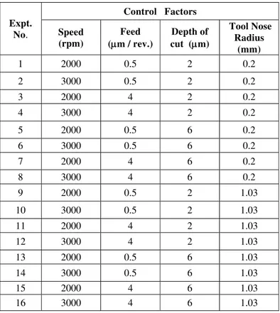
Table 2. Experimental Design Matrix
Expt. No.
Control Factors
Speed (rpm)
Feed (m / rev.)
Depth of cut (m)
Tool Nose Radius
(mm)
1 2000 0.5 2 0.2
2 3000 0.5 2 0.2
3 2000 4 2 0.2
4 3000 4 2 0.2
5 2000 0.5 6 0.2
6 3000 0.5 6 0.2
7 2000 4 6 0.2
8 3000 4 6 0.2
9 2000 0.5 2 1.03
10 3000 0.5 2 1.03
11 2000 4 2 1.03
12 3000 4 2 1.03
13 2000 0.5 6 1.03
14 3000 0.5 6 1.03
15 2000 4 6 1.03
16 3000 4 6 1.03
Table 3. Result Matrix
Expt. No. 1 2 3 4 5 6 7 8 9 10 11 12 13 14 15 16
Surface Roughness
(Ra) (nm)
16.3 15.4 12.4 14.8 27.5 27.9 16.8 11.3 10.2 7.9 6.3 10.7 9.1 6.9 7.3 5.8
Fig.3. Depth of Cut =2µm & Tool Nose Radius= 0.2mm
Fig.3 shows the relationship of spindle speed vs. surface roughness with change in feed rate. At lower depth of cut and smaller tool nose radius with low feed as 0.5µm/revolution., improves the surface roughness from 16.3 nm to 15.4nm, when spindle speed increases. With higher feed as 4µm/revolution and low speed, surface roughness value is low as 12.4nm, but deteriorates to 14.8nm, when speed increases. The Fig. 3 gives that low depth, small nose radius, high feed and low spindle speed is the combination of better surface finish.
Fig.4 shows the relationship of spindle speed vs. surface roughness with change in feed rate. At higher depth of cut and smaller tool nose radius with low feed as 0.5µm/revolution, deteriorates the surface roughness from 27.5nm to 27.9, when spindle speed increases. With higher feed as 4 µm/revolution and low speed, surface roughness value is low but goes on improving from 16.8nm to 11.3nm, when speed increases. The Fig.4 gives that high depth, small nose radius, high feed and high spindle speed is the combination of better surface finish.
Fig.4. Depth of Cut =6µm & Tool Nose Radius= 0.2mm
Fig.5 shows the relationship of spindle speed vs. surface roughness with change in feed rate. At lower depth of cut and bigger tool nose radius with low feed as 0.5µm/revolution, improves the surface roughness from 10.2nm to 7.9nm, when spindle speed increases. With higher feed as 4 µm/revolution and low speed, surface roughness value is low as 6.3nm, but deteriorates to 10.7nm, as speed increases. The Fig.5 gives that low depth, bigger nose radius, high feed and low spindle speed is the combination of better surface finish.
Fig.6 shows the relationship of spindle speed vs. surface roughness with change in feed rate. At higher depth of cut and bigger tool nose radius with low feed as 0.5µm/revolution, improves the surface roughness from 9.1nm to 6.9nm, as spindle speed increases. With higher feed as 4µm/revolution and low speed, surface roughness value is low as 7.3nm and improves to 5.8nm as speed increases. The Fig.6 gives that high depth, bigger nose radius, high feed and high spindle speed is the combination of better surface finish.
10 11 12 13 14 15 16 17
2000 3000
Feed=0.5 microns Feed=4 microns
Spindle Speed (rpm)
Surface
R
oughness
(nm
)
10 12 14 16 18 20 22 24 26 28 30
2000 3000
Feed=0.5 microns Feed=4 microns
Spindle Speed (rpm)
S
urfa
ce Roughne
ss (nm
Fig.5. Depth of Cut =2µm & Tool Nose Radius= 1.03mm
Fig.6. Depth of Cut =6µm & Tool Nose Radius= 1.03mm
6 6.5 7 7.5 8 8.5 9 9.5 10 10.5 11 2000 3000 Feed=0.5 microns Feed=4 microns
Spindle Speed (rpm)
Surfac e R oughness (nm ) 5.5 6 6.5 7 7.5 8 8.5 9 9.5 2000 3000 Feed=0.5 microns Feed=4 microns
Spindle Speed (rpm)
S urfa ce Roughne ss (nm ) 5 10 15 20 25 30 2000 3000
Depth of Cut =2µm & Tool Nose Radius= 0.2mm, Feed=0.5 microns
Depth of Cut =2µm & Tool Nose Radius= 0.2mm, Feed=4 microns
Depth of Cut =6µm & Tool Nose Radius= 0.2mm, Feed=0.5 microns
Depth of Cut =6µm & Tool Nose Radius= 0.2mm, Feed=4 microns
Depth of Cut =2µm & Tool Nose Radius= 1.03mm,Feed=0.5 microns
Depth of Cut =2µm & Tool Nose Radius= 1.03mm, Feed=4 microns
Depth of Cut =6µm & Tool Nose Radius= 1.03mm,Feed=0.5 microns
Depth of Cut =6µm & Tool Nose Radius= 1.03mm,Feed=4 microns
Spindle Speed (rpm)
Fig.7 shows the superimposition of all parameters result and relationship of spindle speed vs. surface roughness. The depth of cut, spindle speed, feed and tool nose radius controls the surface finish of the workpiece. The tool nose radius is very dominating parameter amongst the all parameters. From experimental investigations and with the help of Fig.7, it is found that as bigger tool nose radius is used, surface roughness (Ra) improves with higher depth, high speed and high feed.
5. Conclusion
This work was carried out to investigate the viability of diamond turning on OFHC copper. In this work, the effect of combination of various control factors on the diamond machining performance on OFHC copper was measured. The measure of performance was surface roughness.
Based on the experimental investigations following concluding remarks can be made: From diamond turning nano-meter level surface finish can be achieved.
The surface roughness value of 5.8 nm has been achieved on the OFHC copper material.
The tool nose radius is very dominating parameter amongst the all parameter, as bigger tool nose radius surface roughness (Ra) improves with higher depth, high speed and high feed rate. References
[1] Taniguchi N. (1996): Nanotechnology, Oxford University Press.
[2] Gao W., Hocken R.J., Patten J.A., Lovingood J., Lucca D.A. (2000): Construction and Testing of a Nano-machining Instrument, Journal of Int. Societies for Precision Engineering and Nanotechnology; 24, pp. 320-328.
[3] Balasubramaniam R., Dewangan T., Jacob J., Suri V.K., (2005): Some studies on the error sources in diamond turning lathe, COPEN, pp.63-68.
[4] Balasubramaniam R., Dewangan T., Surendran N.V., Jacob J, Suri V.K., (2006): Some studies on the form errors generated on the components machined on single point diamond turning, 22nd
AIMTDR, pp.362-366