Abstract
In conventional composite construction involving hot-rolled steel section, the composite action is usually achieved by using conven-tional headed shear studs connectors. However, use of headed studs is not practical for cold-formed steel (CFS) section due to its very thin form that is difficult to weld. A suitable bolt and nut type shear connector was proposed; experimental tests were car-ried out to evaluate its performance. This study also investigated the use of Self-Compacting Concrete (SCC) integrated with CFS by means of bolted shear connectors to develop composite action. Therefore, the objective of this paper was to investigate the per-formance of bolted shear connectors in SCC integrated with CFS section as composite beam system. Eighteen push-out test speci-mens comprising of M12, M14 and M16 sized bolted shear con-nector of grade 8.8 with longitudinal spacings of 150 mm, 250 mm and 300 mm centers were fabricated, cast and tested until failure. The experimental results showed that all bolted shear connectors possessed a good shear resistance capacity. Not much difference in strength capacity of specimens with M14 and M16 bolted shear connectors was found, perhaps due to CFS failure. Varying the size and longitudinal spacing of the bolted shear connectors re-vealed that the connectors’ strength capacity changed slightly between M14 and M16 bolts specimens but, significantly for M12 bolt specimens.
Keywords
Bolted Shear Connectors, Self-Compacting Concrete, Cold-Formed Steel, Composite Beam, Longitudinal Spacing, Push-out Test.
Bolted Shear Connectors Performance in Self-Compacting
Concrete Integrated with Cold-Formed Steel Section
1 INTRODUCTION
Steel-concrete composite beam has been in use as a structural member in buildings and bridges for decades (Pavlovic et al., 2014). In composite beam, the shear connection between steel and concrete
Mustapha Muhammad Lawan a Mahmood Md. Tahir b
Jahangir Mirza c
a Construction Research Centre, Faculty
of Civil Engineering, Universiti Teknologi Malaysia, 81310, Johor, Malaysia, mlmus-tapha@yahoo.com
b Construction Research Centre, Faculty
of Civil Engineering, Universiti Teknologi Malaysia, 81310, Johor, Malaysia, mahmoodtahir@utm.my
c Construction Research Centre, Faculty
of Civil Engineering, Universiti Teknologi Malaysia, 81310, Johor, Malaysia, mir-za7861@gmail.com
http://dx.doi.org/10.1590/1679-78252004
slab is inherently significant, because it resists separation between the two components and it also enhances longitudinal shear transmission (Kim et al., 2011). The most common form of shear con-nection in composite beams system is the use of mechanical devices referred as shear connectors (Parakash et al., 2012). Conventional shear connection mechanism with headed studs shear con-nectors is the most widely used system. The stud concon-nectors are welded to a steel flange and en-cased in concrete to provide the composite action (Pallares and Hajjar, 2010). The strength and ductility of shear connectors can be examined through push-out test, in which two concrete compo-site slabs are connected to both flanges of the steel beam.
A significant number of research works on push-out test using different types of studs with dif-ferent types of steel sections have been published. For instance, a push-out test conducted by Xu, et al. (2012) used headed studs shear connectors on six specimens which were tested to failure. Smith and Couchman (2010) conducted push-out test on nine test specimens. They concluded that suffi-cient ductility of the shear connectors was achieved. Tahir, et al. (2009) also developed a pinned-connected shear stud system in composite beam using a hot rolled steel section which was subjected to push-out test. They concluded that the strength and ductility of the pinned-connected stud sys-tem could be improved by increasing the penetration depth of the pins and the material of the base plate used in which the studs were installed. Strength of stud connectors in lightweight and normal weight concrete was investigated by Ollgaard et al. (1971). The authors concluded that the stud connectors embedded in the normal-weight and light-weight concrete, were influenced by the con-crete strength. Lam (2007) investigated the capacities of headed stud connectors in composite steel beams with hollowcore concrete slabs. He concluded that good shear resistance capacity was achieved in the hollowcore concrete slabs. Bamaga (2013) studied the possibility of using Cold-Formed Steel (CFS) with headed stud shear connectors welded on the flanges of CFS by push-out test. In the study, 16 mm diameter headed stud shear connector was used and the results attested better performance in strength and ductility when compared with other shear connectors used in the study. Push-out test using CFS in composite beam was also conducted by Bamaga and Tahir (2013). They used a variety of shear connection mechanisms (single bracket CFS shear connector, double bracket CFS shear connector and hot rolled steel (HRS) plate shear connector). The shear connectors showed high strength and ductility. A study on push-out test using CFS was investigat-ed by Alenezi et al. (2013) and shear connectors usinvestigat-ed includes: bar angle bolt (10 mm diameter), self-drilling screws (6.3 mm diameter) and bolts (10 mm diameter). They found that the bolt (M10) showed a better performance as compared with other connectors used.
strength-be used for strengthening non-composite floor systems in existing buildings with flat soffit solid slabs. The authors concluded that post-installed bolted shear connectors were feasible for the strengthening of the bridge girders. The performance and viability of bolted shear connectors as demountable con-nectors in composite system was investigated by Moynihan and Allwood (2014). Their findings point-ed out that the boltpoint-ed shear connectors possess good strength capacities.
It is evident in practical situations that there were important applications for concrete where compaction becomes problem or physically not feasible (Bartos, 2013). For instance, such applica-tions could be found in construction works underwater, foundation works consisting of large diame-ter concrete piles, very deep concrete diaphragm walling etc. Therefore, a concrete mix required for such kind of applications had to be self-compacting (De Schutter et al., 2008). Therefore, this study aimed to investigates the use of Self-Compacting Concrete (SCC) instead of conventional Normal Vibrated Concrete (NVC) as lack of inadequate compaction on the latter lead to creation of air voids. Thus, leading to the weakening of the concrete mass which could result to structural failure. But, the SCC does not require any external vibration for its compaction to be achieved, because that is achieved by its own self weight and homogeneity is maintained even in the presence of con-gested reinforcement.
A review of previous studies on bolted shear connectors is clearly indicative that the concept of using such type of connectors with CFS section and concrete is getting popular and its advantages have been proven by many researchers (Hanaor, 2000; Alenezi et al., 2013; Saggaff et al., 2015). However, the use of CFS with SCC and bolted shear connectors in a composite beam system is yet to be reported. Previous research reports delineated the following points.
i. None of the research works presented earlier reported the use of CFS with SCC and bolted shear connectors integrated as composite beam system.
ii.None of the studies show the performance of CFS-SCC and bolted shear connectors in com-posite construction in full scale testing.
Hence, this research study was undertaken to assess the shear capacity performance of bolted shear connectors used with CFS and SCC for composite beam system by means of push-out tests.
2 MATERIALS AND METHODS
2.1 Materials
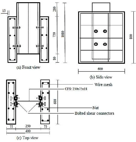
The materials comprised of CFS lipped channel section of 250 mm x 75 mm x 18 mm and thickness of 2.3 mm; High tensile bolts of M12 x 75 mm, M14 x 75 mm and M16 x 75 mm of grade 8.8; weld-ed wire fabric mesh A 142 of 6 mm diameter spacweld-ed 200 mm x 200 mm and ready-mixweld-ed SCC of 40 N/mm2 with a slump flow ranged between 550 mm – 650 mm. All materials were tested in the Structures and Materials Laboratory of Universiti Teknologi Malaysia to establish the properties.
2.2 Material Properties
2.2.1 Cold-formed Steel Section (CFS)
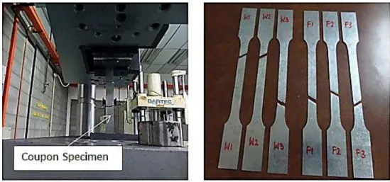
Properties of the CFS section were evaluated by coupon tensile test. The size of coupon and the procedure of the tests were conducted based on BS EN10002-1 (2001). The test was conducted so that the yield and the ultimate stresses of the steel section could be obtained, on a Universal Test-ing Machine INSTRON 600DX. Three specimens, each from the web and flange of the steel were taken and denoted as W1, W2, W3 and F1, F2, F3 respectively. The results are presented in Table 1. Figure 1 shows the test set-up and the tested specimens.
Web Flange
Avrg fu/fy CFS Thickness, t
(mm) W1 W2 W3 F1 F2 F3
fy 490.88 478.33 480.62 488.93 490.91 494.93 487.43
1.07 2.3
fu 526.84 513.01 516.09 526.61 528.49 532.04 523.85
Es 212.88 209.65 214.59 227.09 199.37 204.98 211.43
fy: yield stress (N/ mm2); fu: ultimate stress (N/ mm2); Es: elasticity modulus (kN/ mm2).
Table 1: Result of CFS coupon tensile test.
Figure 1: Test set-up and tested coupon specimens.
2.2.2 Bolted Shear Connectors
Bolt size (mm) Maximum load (kN) Average Max. load (kN) Yield stress, fy (N/mm2)
Average fy (N/mm2)
Ultimate stress, fu (N/mm2)
Average fu (N/mm2)
fu/f y
Average fu/fy (N/mm2)
M12-1 72
71 767 761 852 843 1.11 1.11
M12-2 70 755 834 1.10
M14-1 95
96 715 720 813 807 1.14 1.12
M14-2 97 725 800 1.10
M16-1 144
143 780 768 897 897 1.15 1.17
M16-2 141 755 896 1.19
Table 2: Result of bolts tensile test.
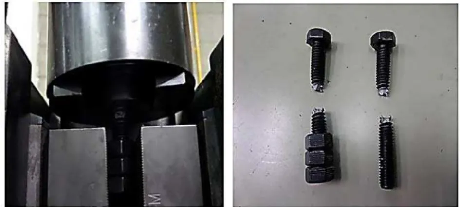
Figure 2: Test set-up and tested bolt specimen.
2.2.3 Welded Wire Fabric Reinforcement
The wire mesh fabric used in this study was of 5.8 mm thick in actual diameter and spaced 200 mm x- 200 mm centers. The steel bar of the welded wire fabric was of grade 460 N/ mm2 and was test-ed for tensile in order to obtain the yield and the ultimate strengths in accordance with BS4449 (1997). Three sample specimens were randomly selected for the test, and the test was conducted using a Universal Testing Machine INSTRON 8801. Result is shown in Table 3. Figure 3 shows the test set-up and the tested specimens.
Specimen
Average fu/fy Diameter (mm)
B1 B2 B3 Yield strength, fy
(N/mm2) 512.46 495.19 499.66 502.44
1.18 5.8
Ultimate strength, fu
(N/mm2) 603.87 578.44 602.48 594.93
Figure 3: Test set-up and tested mesh specimen.
2.2.4 Self-Compacting Concrete (SCC)
The concrete used was a ready mixed Self-Compacting Concrete (SCC) designed for 40 N/mm2 cube compressive strength at 28 days and a slump flow of 550 mm- 650 mm. Fresh properties of the SCC were evaluated in accordance with EFNARC (2005) and BS EN206-9 (2010); while the hard-ened properties of the SCC, i.e. compressive strength (fcu) and elastic modulus (Ec) were obtained
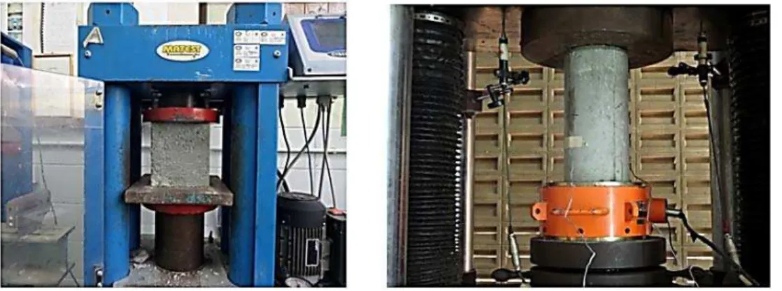
by cube compression and cylinder tests respectively. The compression test was conducted in accord-ance with BS12390-3 (2009) and the cylinder test was conducted in accordaccord-ance with BS1881-121 (1983). Both fresh and hardened properties test results are presented in Table 4. Figure 4 shows the test set-up and the tested specimens.
Fresh
Slump flow (mm) T500 (sec) J-ring slump (mm) T500j (sec) V-funnel time (sec)
590 2.0 650 2.0 4.0
610 1.5 635 2.0 4.0
630 1.5 620 1.5 3.0
Average 610 2.0 635 2.0 4.0
Hardened
Cube compressive strength, fcu (N/mm2)
Cylinder compressive strength, fcc (N/mm2)
Splitting tensile stress, fct, sp (N/mm2)
Elastic Modulus, Ec (kN/mm2)
40.25 32.20 3.0 28.68
42.21 33.77 3.5 29.23
42.11 33.69 2.9 29.04
Average 41.52 33.22 3.1 28.98
Figure 4: Cube and Cylinder test of concrete.
2.3 Push-out test 2.3.1 Test Specimens
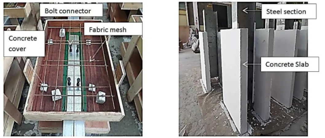
Figure 5: Installed bolt connectors for push-out test specimen.
Figure 7: Push-out test specimens before and after casting.
2.3.2. Test Set-up and Instrumentation
The test set-up is shown in Figure 8. Each push-out specimen was placed on 3 mm thick plywood and on 800 mm x 800 mm x 50 mm thick steel section, in order to properly place the concrete slabs. A restrain using steel angle section of 2000 mm length and 10 mm thickness was provided to hinge the movement of the test specimen while load was applied. Load using DARTEC Jack machine was applied on the upper part of the steel beam which has a load cell capacity of 2000 kN. Each push-out specimen was equipped with two linear variable displacement transducer (LVDT), each on ei-ther side of the steel beam web to measure slip in the vertical direction between the concrete slab and the steel beam. The LVDT’s and the load cell were all connected to a data logger. Average reading of the LVDTs was used for the result analysis. The load was applied at a constant rate of 0.2 kN/s up to 40% of the predicted failure load. The loading was cycled three times (loading and unloading) between 5% and 40% of the expected failure load. After the cyclic loading, the load was then applied until failure. The loading was stopped when a drop of 20% from the maximum load of the specimen occurred or the specimen failed to resist any additional load as stated in Eurocode 4.
3 EXPERIMENTAL RESULTS AND DISCUSSIONS
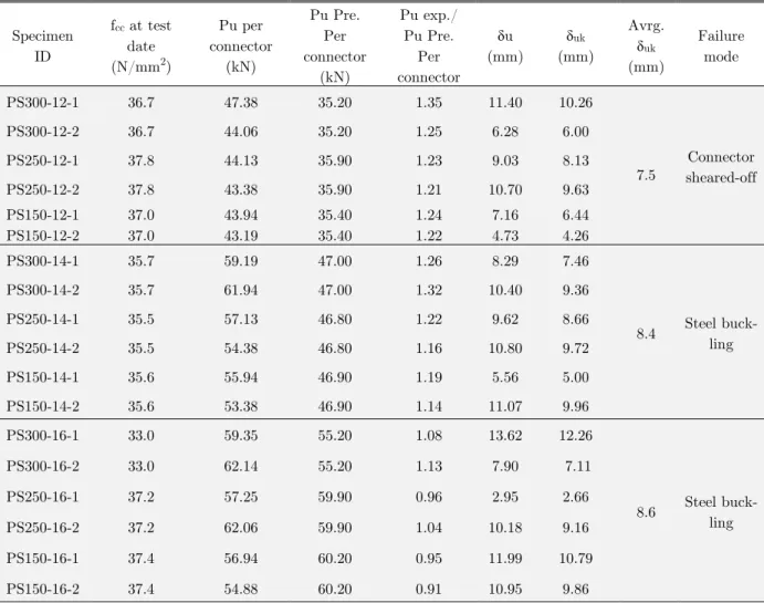
The push-out test result is presented in Table 5. Figure 9 shows the load-slip curves of tested spec-imens. From Table 5, the predicted values were obtained based on Equations (1) and (2) whichever is smaller as provided in Eurocode 4.
2 0.8 4 u Rd v
d
f
P
(1)Or 2 0.29 cm ck Rd v
f
d
E
P
(2)Whichever is smaller from the equations; With:
0.2 sc 1 3 sc 4
for
d d
h
h
(3)
1.0 sc
for d
h
(4)
Where:
Rd
P
; Design resistance of shear connectoru
f
: Ultimate tensile strength of the stud (bolt) taken as the maximum value in this studyd
: Shank diameter of the stud (bolt)v
: Safety factor (taken as 1.25)ck
f : Characteristic cylinder compressive strength
: Dimensional coefficient
cm
E
: Concrete modulussc
h
: Height of shear connector3.1 Failure Modes
The failure modes of the tested specimens can be categorized as;
(i) Shear connector failure either by deformation, pull-out and/or shear-off. (ii) Concrete failure by crushing.
(iii) Steel failure by buckling of either the flange or web or both. (iv) Bearing failure of steel section.
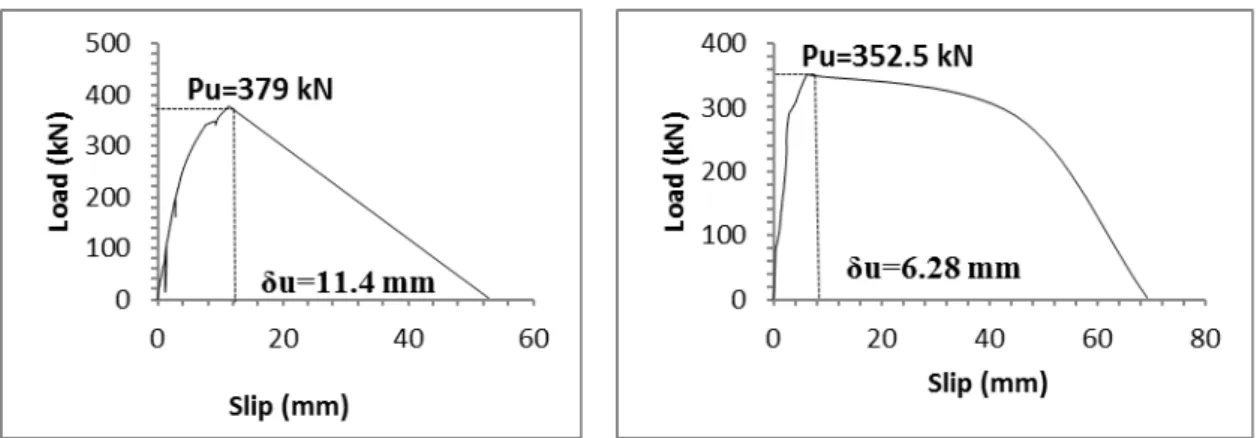
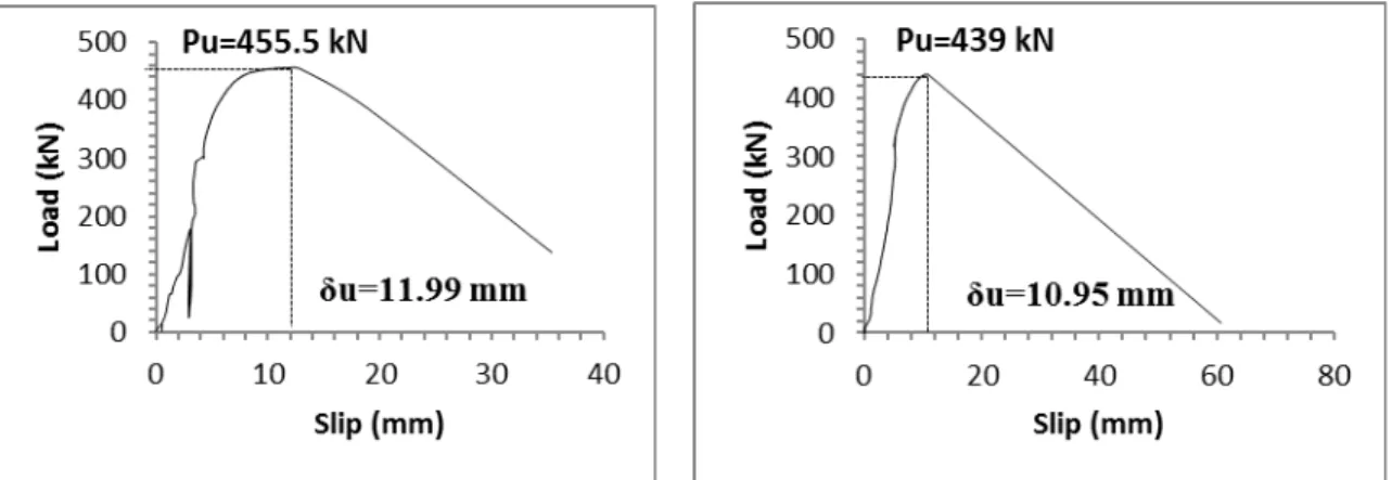
indicated that the load slip responses for specimens with M12 bolts seemed to exhibit a similar pat-tern as shown in Figure 10a (i) through (vi). It can be observed that a remarkable shear resistance and slip at ultimate loads were attained by the specimens. Specimens with M14 bolt manifested good shear resistance and good slip at ultimate loads, as shown in Figure 10b (i) through (vi). Same explanation is extended to the specimens with M16 bolted shear connectors. They also showed a remarkable increase in the shear resistance values as well as slip at ultimate loads (see Figure 10c (i) through (vi)). The failure mode of the test specimens with bolt diameters of M14 and M16 could be attributed to the failure of the steel section due to flange buckling. Perhaps high resistance to the applied load by the concrete slabs and bolted shear connectors could be responsible for it. The failure due to steel buckling occurred at the top shear connector of the specimens that was near the position of the load application. It then extended upwards from the initial position where it had occurred, to the part where the CFS was not covered by the concrete slab which also resulted in the web buckling (see Figure 11a & b). Considering the load-slip curves, it can be seen that loading and unloading on some test specimens were done. This was to ensure that equilibrium was maintained from the loading set-up before the other specimen was tested in the category. From the load-slip curves of specimens with M14 bolt connector, it can be observed that a non-linear behavior was demonstrated by the specimens with exception of PS150-14-1 specimen. The specimen attained a slip at ultimate load of 5.56 mm, and it resulted from failure of CFS section that occurred which prevented further resistance of the applied load by the specimen. However, the specimen demon-strated good resistance capability of an ultimate load of 447.5 kN despite the CFS section failure. For specimens with M16 bolt connector, similar observation was made. The specimens’ load-slip curves behaved non-linearly with good ultimate load resistance and large slip at ultimate load was demonstrated. The non-linearity resulted due to the failure of CFS that started at the advanced stage of loading before reaching the ultimate failure load. The same scenario was observed for PS250-16-1 specimen though, it showed very low slip due to the resistance of the load by the con-crete and the shear connector up to the ultimate load level. No significant difference in the shear resistance capacities of M14 and M16 bolts specimens were observed due to the failure of the CFS. But, the shear resistance capacity was seen to be slightly increased. It is evident that the maximum design capacity of the specimens with M14 and M16 bolts connectors is based on the tested value obtained which failed due to CFS failure. However, the value obtained for M16 bolt specimen at 300 mm spacing had an increment of 17% shear capacity over a conventional headed shear studs size of 16 mm at 325 mm spacing used by Bamaga (2013). This could be attributed to the welding of the stud connector on the CFS. However, it shows that the shear connection mechanism em-ployed in this study has the ability to increase the shear capacity of shear connectors. Again, refer-ring to Table 5, it can be observed that the bolted shear connectors used attained an average char-acteristic slip capacity (δuk) of more than 6 mm recommended by Eurocode 4. A shear connector is
Specimen ID
fcc at test
date (N/mm2)
Pu per connector (kN) Pu Pre. Per connector (kN) Pu exp./ Pu Pre. Per connector ẟu (mm) ẟuk (mm) Avrg. ẟuk (mm) Failure mode
PS300-12-1 36.7 47.38 35.20 1.35 11.40 10.26
Connector sheared-off
PS300-12-2 36.7 44.06 35.20 1.25 6.28 6.00
PS250-12-1 37.8 44.13 35.90 1.23 9.03 8.13
7.5
PS250-12-2 37.8 43.38 35.90 1.21 10.70 9.63
PS150-12-1 PS150-12-2 37.0 37.0 43.94 43.19 35.40 35.40 1.24 1.22 7.16 4.73 6.44 4.26
PS300-14-1 35.7 59.19 47.00 1.26 8.29 7.46
Steel buck-ling
PS300-14-2 35.7 61.94 47.00 1.32 10.40 9.36
PS250-14-1 35.5 57.13 46.80 1.22 9.62 8.66
8.4
PS250-14-2 35.5 54.38 46.80 1.16 10.80 9.72
PS150-14-1 35.6 55.94 46.90 1.19 5.56 5.00
PS150-14-2 35.6 53.38 46.90 1.14 11.07 9.96
PS300-16-1 33.0 59.35 55.20 1.08 13.62 12.26
Steel buck-ling
PS300-16-2 33.0 62.14 55.20 1.13 7.90 7.11
PS250-16-1 37.2 57.25 59.90 0.96 2.95 2.66
8.6
PS250-16-2 37.2 62.06 59.90 1.04 10.18 9.16
PS150-16-1 37.4 56.94 60.20 0.95 11.99 10.79
PS150-16-2 37.4 54.88 60.20 0.91 10.95 9.86
PS300-16-1: Push-out specimen at 300 mm longitudinal spacing with M16 bolt connector number one; Pu: ultimate load; Pu Pre.: Predicted ultimate load; uk: characteristics slip capacity.
Table 5: Push-out test result.
Figure 10a: (i) PS300-12-1 (ii) PS300-12-2.
Figure 10a: (iii) PS250-12-1 (iv) PS250-12-2.
Figure 10b: (i) PS300-14-1 (ii) PS300-14-2.
Figure 10b: (iii) PS250-14-1 (iv) PS250-14-2.
Figure 10c: (i) PS300-16-1 (ii) PS300-16-2.
Figure 10c: (iii) PS250-16-1 (iv) PS250-16-2.
Figure 10c: (v) PS150-16-1 (vi) PS150-16-2.
(a) Specimen with M16 bolt (b) Specimen with M14 bolt
Figure 11: Failure mode of specimens with M16 and M14 bolts connectors.
3.2 Effect of Shear Connector Size and Longitudinal Spacing on the Ultimate Load (Pu)
The effect of shear connector size and longitudinal spacing was investigated in order to establish their influence on shear strength capacity of the shear connectors. It was observed that an increase in shear strength capacity of 32.4% between M12 and M14; 32.9% between M12 and M16; 0.3% between M14 and M16 bolted shear connectors when used at a spacing of 300 mm. An increase in the strength capacity is observed between M12 and M14 of 27.4%; between M12 and M16 of 36.4%; between M14 and M16 of 7.0% bolts connectors respectively, when used at a spacing of 250 mm. Moreover again, an increase of 25.5% was also observed between M12 and M14; 28.4% between M12 and M16; 2.3% between M14 and M16 bolts respectively for a longitudinal spacing of 150 mm. The increase in the strength capacities observed with respect to the shear connector size is in agreement with the findings of (Hanaor, 2000; Irwan et al., 2011; Alenezi et al., 2013). The increase in shear strength capacity observed with respect to the longitudinal spacing (see Figure 12) shown to have influenced the ultimate load capacity. It also agreed well with the observation made by Bonilla Rocha et al. (2012). Effect of shear connector size on ultimate load capacity is presented in Table 6.
6
A
ve
ra
ge
u
lti
m
ate
load
(k
N
)
Spaci g
M 6 speci e s M speci e s
M speci e s
Specimen ID Average
Pu, exp. (kN) Increase of Pu (%)
PS300-12 365.8 - -
PS300-14 484.5 PS12vsPS14
32.4 -
PS300-16 486 PS12vsPS16
32.9
PS14vsPS16 0.3
PS250-12 350 - -
PS250-14 446 PS12vsPS14
27.4 -
PS250-16 477.3 PS12vsPS16
36.4
PS14vsPS16 7.0
PS150-12 348.5 - -
PS150-14 437.3 PS12vsPS14
25.5 -
PS150-16 447.3 PS12vsPS16
28.4
PS14vsPS16 2.3
Table 6: Effect of shear connector size on ultimate load capacity.
4 CONCLUSIONS
Push-out test for specimens with M12, M14 and M16 bolts of grade 8.8 used as shear connectors were conducted. The effect of shear connectors’ size and longitudinal spacings were investigated in order to establish their influence on the ultimate shear carrying capacity of the shear connectors. Following conclusions can be drawn:
Among the proposed bolted shear connectors, M12 bolted shear connector performed well with the CFS of 2.3 mm thick.
Not much difference in strength capacity was noted between M14 and M16 bolted shear con-nectors as the failure of the specimens occurred at the CFS.
The shear connectors used can be classified as ductile connectors as they achieved an average characteristic slip of more than 6 mm as recommended by Eurocode 4.
Size of shear connector had shown to have influenced the strength capacity of the shear con-nectors on the ultimate load capacity as it increased from M12 to M14 and to M16.
Longitudinal spacing of shear connector also had shown to have influenced the ultimate load capacity of the specimens as it increased from 150mm to 250mm and to 300mm.
The same configurations of test specimens considered in this study should be investigated with inclusion of stiffeners in the CFS web to strengthen the steel section for specimens with M14 and M16 bolt connectors.
Acknowledgement
The work reported in this study was supported by Universiti Teknologi Malaysia Construction Research Centre (UTM-CRC) with a grant vote number 06H41. The authors gratefully acknowledged the support. The first author appreciated the support received from the Technicians of Structures Laboratory of UTM.
References
Alenezi, K., Talal, A., Tahir, M. M., Mohamed Ragaee, Badr, K., Bamaga, S. O. (2013). Strengthen of Cold-Formed Steel Column with Ferrocement Jacket: Push out Tests. International Journal of Civil, Architectural Science and Engineering 7:262-272.
Bamaga, S. O. (2013). Structural Behaviour of Composite Beam with Cold-formed Steel Section, PhD Thesis (in English), Universiti Teknologi Malaysia, Malaysia.
Bamaga, S. O., Tahir, M. M. (2013). Towards Light-Weight Composite Construction: Innovative Shear Connector for Composite Beams. Applied Mechanics and Materials 351-352:427-433.
Bartos, P. (2013). Fresh concrete: properties and tests. Amsterdam, the Netherlands: Elsevier Science.
Bonilla Rocha, J. D., Arrizabalaga, E. M., Larrua, Q., Rafael, Recarey, M., Carlos A. (2012). Behavior and Strength of welded stud shear connectors in composite beam. Revista Facultad de Ingenieria Universidad de Antioquia 63:93-104.
BS 4449. (1997). Specification for carbon steel bars for the reinforcement of concrete. British Standard Institution, London.
BS EN ISO 898-1. (1999). Mechanical properties of fasteners made of carbon steel and alloy steel. Part 1: Bolts, screws and studs. British Standard Institution, London.
BS EN10002-1. (2001). Metallic Materials-Tensile Testing. Part 1: Method of test at ambient temperature. British Standard Institution, London.
BS EN12390-3. (2009). Testing hardened concrete-Part 3: Compressive strength of test specimens. British Standard Institution, London.
BS EN1994-1-1. (2004). Eurocode 4: Design of composite steel and concrete structures- Part 1-1: General rules and rules for buildings. British Standard Institution, London.
BS EN206-9. (2010). Concrete. Part 9: Additional Rules for Self-compacting Concrete. British Standard Institution, London.
BS1881-121. (1983). Testing Concrete-Part 121: Method for determination of static modulus of elasticity in compres-sion. British Standard Institution, London.
De Schutter, G., Gibbs, J., Domone, P. and Bartos, P. J. (2008). Self-compacting concrete. Scotland, UK: Whittles Publishing.
EFNARC. (2005). The European Guidelines for Self-Compacting Concrete: specification, Production and Use. Euro-pean Union, London.
Hanaor, A. (2000). Tests of composite beams with cold-formed sections. Journal of Constructional Steel Research 54:245–264.
Irwan, J. M., Hanizah, A. H., Azmi, I., Koh, H. B. (2011). Large-scale test of symmetric cold-formed steel (CFS)– concrete composite beams with BTTST enhancement. Journal of Constructional Steel Research 67:720-726.
Kim, B., Howard, D. W., Roy Cairns. (2001). The behaviour of through deck welded shear connectors: an experi-mental and numerical study. Journal of Constructional Steel Research 57:1359-1380.
Lam, D. (2007). Capacities of headed stud shear connectors in composite steel beams with precast hollowcore slabs. Journal of Constructional Steel Research 63:1160-1174.
Moynihan, M. C., Allwood, J. M. (2014). Viability and performance of demountable composite connectors. Journal of Constructional Steel Research 99:47-56.
Ollgaard, J. G., Slutter, R. G., Fisher, J. W. (1971). Shear strength of stud connectors in lightweight and normal weight concrete. AISC Engineering Journal 1:1971.
Pallarés, L., Hajjar, J. F. (2010). Headed steel stud anchors in composite structures, Part I: Shear. Journal of Con-structional Steel Research 66:198-212.
Pavlović, M., Marković, Z., Veljković, M., Buđevac, D. (2013). Bolted shear connectors vs. headed studs behaviour in push-out tests. Journal of Constructional Steel Research 88:134-149.
Pavlovic, M., Spremic, M., Markovic, Z., Budjevac, D., Veljkovic, M. (2014). Recent research of shear connection in prefabricated steel-concrete composite beams. Istrazivanja i projektovanja za privredu 12:75-80.
Prakash, A., Anandavalli, N., K. Madheswaran, C., Lakshmanan, N. (2012). Modified Push-out Tests for Determin-ing Shear Strength and Stiffness of HSS Stud Connector-Experimental Study. International Journal of Composite Materials 2:22-31.
Saggaff, A., Alhajri, T., Tahir, M. M., Alenezi, K., Tan, C. S., Sulaiman, A., Lawan, M. M., Ragaee, M. (2015). Experimental and Analytical Study of Various Shear Connectors Used for Cold-Formed Steel-Ferrocement Compo-site Beam. Applied Mechanics and Materials 754-755:315-319.
Smith, A. L., Couchman, G. H. (2010). Strength and ductility of headed stud shear connectors in profiled steel sheet-ing. Journal of Constructional Steel Research 66:748-754.
Tahir, M. M., Shek, P. N., Tan, C. S. (2009). Push-off tests on pin-connected shear studs with composite steel– concrete beams. Construction and Building Materials 23:3024-3033.
