Abstract
The design of a suspension system emphasizes weight reduction in this high-computation technology era. Understanding that the reduction of suspension mass can lead to cost and material reduc-tion is important; moreover, the riding performance of the vehicle should be improved. Topology and topography structure optimiza-tion for the spring lower seat is performed to reduce the weight of a passenger car spring lower seat design under stress and structure compliance constraints. Topology optimization is performed to identify the density of the required elements, whereas topography optimization is utilized to strengthen the structure of the lower seat by applying bead parameters in the model. Based on topology optimization, the mass of the model is improved by a reduction of 36.5%. Topography optimization is subsequently performed to fine-tune the topology-optimized model. Beads are added to the model to strengthen the stiffness of the structure. The topography-optimized model has successfully increased compliance by 27% compared with the sole topological optimized design. With the combination of topology and topography optimization techniques, the weight of coil spring lower seat has been successfully reduced while preserving the strength. Suitable sheet materials are pro-posed to match the optimized coil spring lower seat design.
Keywords
Topology, Topography, Spring Lower Seat, Explicit, Optimization
Topological and Topographical Optimization
of Automotive Spring Lower Seat
1 INTRODUCTION
Vehicle weight reduction is devoted to achieving fuel efficiency and reducing material costs. Con-cerns on decreasing the component cost in the automotive industry have recently increased because
Y.S. Kong a S. Abdullah b M.Z. Omar c S.M. Haris d
Department of Mechanical and Materials Engineering, Faculty of Engineering and Built Environment, Universiti Kebagsaan Malaysia, UKM 43600, Selangor, Malay-sia.
Centre for Automotive Research, Faculty of Engineering and Built Environment, Universiti Kebangsaan Malaysia, UKM 43600, Selangor, Malaysia.
Corresponding author:
a [email protected] b [email protected] c [email protected] d [email protected]
http://dx.doi.org/10.1590/1679-78252082
weight reduction of vehicles tends to improve fuel efficiency and reduce harmful emissions. There-fore, a large number of automotive component optimization research works to reduce vehicle weight have been published. For example, Cui et al. (2011) performed a multi-material optimization for car body through material performance indices. His research focused on crashworthiness, where frontal impact and global bending stiffness are considered for material selection. Sakundarini et al. (2013) has also recently performed optimum multi-material selection for lightweight automotive body as-sembly, with recyclability as one of the design parameters. The price of secondary material was considered during the material selection for car door panel.
As outlined in preceding works, the current automotive trend is to build lightweight vehicles (Cue et al. 2011, Sakundarini et al. 2013). Many optimization techniques have been introduced to suit the objective of light weight vehicle. As for material optimization, multimaterial optimization technique has been performed by selecting the most suitable material to achieve its objective func-tion. Zhu et al. (2010) performed an optimization of material model for protective helmets through the FE model. The FE and optimization approach identified the material behavior of ultrasoft mat-ters without the need for a large number of samples. Nowadays, not only material optimization, structural optimization technique has also been extended parallel to the growth on computation power and finite element (FE) method to perform complex analysis and to initiate design concept generation. FE analysis has been widely used in the automotive industry to validate automotive component designs (Gokhale et al. 2008) Concomitant with the existing FE model, topology optimi-zation of component designs can be performed, such as car body structure (Bendsoe et al. 1998) and engine block (Chakravarty 2009). Du et al. (2011) also jointly presented the utilization of topology and topography optimization techniques in performing engine brackets and cover design.
For the past few years, automotive suspension structures have been optimized to obtain large sprung mass–to–unsprung mass ratio (Gillespie 1996) to improve vehicle ride (Rozvany 2009). Therefore, engineers have attempted to design lightweight suspension components, thereby reducing the unsprung mass of the vehicle while preserving the structural strength and compliances. For example, Yu and Kim (1998) replaced steel leaf spring with glass fiber and epoxy to reduce the weight while maintaining the strength of the spring itself. Aluminum castings instead of steel are commonly used in suspension components, such as knuckles and control arms (Miller et al. 2000, Sen and Londhe 2006) to reduce vehicle weight. Cavazzuti et al. (2011) optimized two types of au-tomobile chassis through topology optimization, and the results are significant on saving structural weight. Various efforts have been exerted to reduce the suspension system of vehicles. This observa-tion agrees with the idea that the weight of the coil spring lower seat should be optimized. For op-timization of automotive components, it is important to determine the loads that transmitted to the components (Grubisic 2006), either through FE simulations or experiments.
vehicles which consisted of many contacts between each leave (Hilber et al. 1977). Although the FE explicit scheme able to provide accurate results for highly nonlinear model but the topology and topography optimization technique able to solve only linear static structure (Altair 2014). Therefore, conversion of non-linear response to linear static analysis was performed by Park (2004) to optimize a vehicle model for crashworthiness. For topology optimization in automotive suspension applica-tions, Chiandussi et al. (2004) used topology optimisation to propose a new suspension sub-frame with multiple load cases. Another suspension components optimized using topology algorithm was automotive wheel rims by Zuo et al. (2011) to reduce the volume while maintain the compliances. Based on the previous study, the automotive suspension components are now trending towards topology to shape optimization with extensive growing of commercial software and algorithm such as density based method, hard-kill methods, evolutionary structure optimisation and cellular divi-sion rules (Deaton and Grandhi 2014). The introduced topology optimisation successfully made design of automotive components more insightful.
In this study, an automotive coil spring lower seat was optimized through topology and topog-raphy approaches to reduce the weight of the design. Lightweight designs of automotive compo-nents reduce fuel consumption. Transmitted forces from the coil spring toward the lower seat were identified through explicit nonlinear simulation scheme. The objective of this analysis is to reduce the weight of the coil spring lower seat under stress and compliance constraints. The mass of coil spring lower seat could be optimized in terms of weight through removal of unnecessary design space. Reducing unsprung mass can increase the riding performance of a vehicle and can save mate-rial costs. On the contrary, the stiffness and stress of the models weaken. Therefore, the combina-tion of topology and topography optimizacombina-tion techniques is required. Topology optimizacombina-tion should be conducted first, and in this stage, the compliance of the model increased because of the removal of the excessive region. Topology optimization was followed by topography optimization. The com-pliance of the topology-optimized model was subsequently enhanced with bead application. The stress and displacement results were discussed after optimization.
2 FINITE ELEMENT NONLINEAR EXPLICIT ANALYSIS
In this analysis, FE explicit algorithm was used due to the high number of nonlinear contacts (Al-tair 2014). Explicit nonlinear analysis has been widely adopted in automotive spring analysis (Kong et al 2013). Explicit nonlinear is a time-integrated dynamic scheme that shows stability of conver-gence during simulation. The standard procedures for FE preprocessing should be conducted prior to explicit scheme solving simulation. Compression of the coil spring was performed through FE explicit analysis, which adopted a conditionally stable explicit integration scheme derived from the Newmark scheme for dynamic analysis. The equation of motion for discrete structural models is expressed as follows:
F ku u C u
M .. . (1)
where M is mass, C is viscous damping, and k represents the stiffness matrices.
u
..,u
. , and uu
t
u
t
u
tu
u
u
t t t t t t .. 2 2 1 1 .. 2 .1
(2) .. 1 .. . .
1
u
1u
u
t t t u t (3)where and are the specified coefficients that govern the stability, accuracy, and numerical dissi-pation of the integration method (Chang 2004). A conditionally stable explicit integration scheme can be derived from the Newmark scheme, which is presented as follows:
) ( 2 1 .. 1 .. 2 . .
1
u
t
u
u
u
t t
t t (4).. 2 1 2 1
u
t
tu
u
u
t t
t
t (5)The explicit central difference integration scheme can be derived from the relationships. The central difference scheme is used when explicit analysis is selected. The time step must be smaller than the critical time step to ensure the stability of the solution. Newmark nonlinear analysis efficiently cap-tures energy decay and exhibits a satisfactory long-term performance after being tested (Kane et al. 2000).
Dynamic relaxation is used in the explicit scheme to reduce the dynamic effects. A diagonal damping matrix proportional to the mass matrix is added to the dynamic equation:
M TC 2 (6)
where is the relaxation value and T is the period to be damped. Thus, a viscous stress tensor is added to the stress tensor. In this explicit code, the application of the dashpot force modifies the velocity equation without relaxation as
t t t t t t
V
V
/2
/2
(7)to velocity equation with relaxation as
t t t t t t
V
V
/2
(
1
2
)
/2
(
1
)
(8)where
t
t
(9)When this option is activated, the running time of the whole simulation is increased. However, the damping period for the system is controlled within acceptable limits.
3 OPTIMIZATION USING TOPOLOGY AND TOPOGRAPHY PROCEDURES
in determining the best solutions for the design requirements, which are highly effective and precise. For structure materials, the most frequently adopted optimization techniques are topology and to-pography (Bendsoe et al. 1998).
Topology optimization, together with FE analyses, is suitable in solving structural mechanics problems at early design stage. Topology optimization determines the optimum distribution of ma-terials and voids regardless of the size and shape. Topology optimization generates an optimized material distribution for a set of loads and constraints within a given space. The resulting problem is then solved with optimization methods together with FE method to identify which element is required and which is not. This particular method is known as isotropy solid or empty (ISE) ele-ments (Rozvany 2000). The two main solution strategies to solve the optimization problem with ISE are density (Rozvany 2000 & 2009, Bendsoe 1995 & 1999, Eschenauer et al. 2001) and homoge-nization method.
During topology optimization, the material density of each element is directly used as the de-sign variable. The dede-sign variable varies continuously between 0 and 1 (i.e., 0% or 100% density), which represents the state of void and solid, respectively. The stiffness of the materials is assumed to be linearly dependent on the density. The optimal solution of problems generally involves large gray areas of intermediate densities in the structural domain. The outcomes are not meaningful when the topology of a given material of grey area is applied. This observation is similar to the situation when the same condition applies to the use of different materials within the design space.
In classical density method, optimization problem can be formulated as follows:
min max
min ( )
( )
s.t.{
,
1,...,
T
T
e
C
F u
a
V
e
n
(10)where ρ = [ρ1, ..., ρn]T is the design vector with element densities and a = [a1, …, an]Tis the vector
of element area. Displacements are determined as u(ρ) = K−1(ρ)F. Penalty method is introduced to penalize intermediate densities and to force the final design to be represented by densities of 0 and 1 for each element. The penalization technique used is the “power law representation of elasticity properties,” which can be expressed as follows:
K
k
,(
)
P (11)where k’ is the penalized stiffness matrix of an element, K is the real stiffness matrix of an element,
ρ is the density and p is the penalization factor, which is always greater than 1.
reduce the compliance of the component. Therefore, topography optimization is then applied to regain compliance.
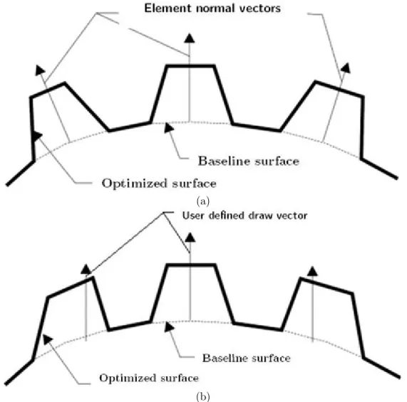
Topography optimization is an advanced form of shape optimization. A design region for a giv-en part is defined, and thgiv-en a pattern of shape variable-based reinforcemgiv-ent within the region is created. Topography is different from topology optimization, that is, topography optimization uti-lizes shape variables instead of density variables. The design region is subdivided into a large num-ber of separate variables, where the influence on the structure is calculated. Hence, the design re-gion is optimized over a series of iterations. For variable generation, the parameters are bead width and draw angle. Beads can be decided to be circular or laid out across the design domain in roughly hexagonal distribution. The spacing of the variables is decided by the minimum bead width and draw angle so that part of the reinforcement patterns forms an angle greater than the draw angle. The details of bead drawing geometry are shown in Figure 1. The beads are inserted to enhance the stiffness of the component.
(a)
(b)
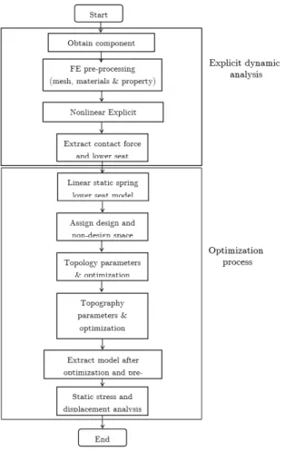
4 METHODOLOGY
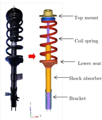
Methodology of optimization in this analysis involved FE explicit analysis, topology and subse-quently topography optimization. Figure 2 shows the process methodology flow of topology and topography optimizations of coil spring lower seat. Nonlinear explicit dynamic analysis was per-formed prior to optimization process. The geometries of the suspension component are required to perform the explicit dynamic analysis. First work on CAD was published by Chiandussi et al. (1998) where CAD model was transferred via a boundary surface displacement field to CAE model. In this analysis, CAD model of the Macpherson strut, which consists of a coil spring, top mount, spring lower seat, shock absorber, and bracket, is prepared through CAD software, as shown in Figure 3. A Macpherson strut is a type of automotive suspension system that consists of a coil spring placed together with a shock absorber through the spring seat (Ishida and Hamada 1984). All the suspen-sion components were meshed and preprocessed with material and property assignation. The meshed Macpherson strut model is shown in Figure 4. The model consists of 83901 nodes and 82025 elements in total. An eight-noded hexa element was used as the primary meshing element for coil spring, whereas a four-noded Quad element was used as an element for spring lower seat. Other components, such as top mount, bracket, and shock absorber, are meshed with three-noded Tria element to reduce FE preprocessing duration.
Figure 3:Macpherson strut front suspension.
Figure 4:Meshed model of Macpherson strut.
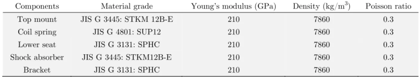
Materials and properties were assigned to the meshed Macpherson strut model. The details for the components are listed in Table 1. In this case, the models are modelled in elastic region due to
Shock absorber Top mount
Bracket
the target of force extraction. Loads and boundary conditions were applied to the Macpherson strut model. The top mount was assumed to be fixed to the body of the vehicle, whereas the loads were applied from the bottom of the strut. All the translational and rotational in X, Y, Z axis of the lower strut has been fixed. Therefore, an imposed displacement of 186 mm was applied on the bracket at the bottom of the Macpherson strut to compress the coil spring into the maximum limit. The simulation was solved through FE explicit dynamic solver. The contact with friction coefficient of 0.2 (Kuttler and Shillor 2001) was applied between the coil spring and spring seat because of the metal-to-metal contact between the coil spring and spring lower seat. These contacts were unable to be modelled in linear static analysis.
Components Material grade Young’s modulus (GPa) Density (kg/m3) Poisson ratio
Top mount JIS G 3445: STKM 12B-E 210 7860 0.3
Coil spring JIS G 4801: SUP12 210 7860 0.3
Lower seat JIS G 3131: SPHC 210 7860 0.3
Shock absorber JIS G 3445: STKM12B-E 210 7860 0.3
Bracket JIS G 3131: SPHC 210 7860 0.3
Table 1: General properties of Macpherson strut components.
The explicit dynamic simulation resulted in the extraction of the maximum contact forces be-tween the coil spring and spring lower seat. The loads were used for the linear static analysis and topology optimization of spring lower seat. During topology optimization, the objective function of minimized mass was defined. At the same time, design constraints were applied to fix the design requirement (e.g., stress and compliance). Topology optimization of structures with mechanical load that are subjected to stress constraints were applied (Deaton and Gandhi 2015). The upper bounda-ry of the stress and compliance constraint was defined. The iterations of the simulation were ob-tained after the simulation was completed. The function of optimization can be written as follows:
Min
f
j(
x
)
(12)subject to fk(x) ≤ Ɛk, k = 1, …, p, k p where fj is the objective function and fk(x) is the design
con-straint. For this simulation, the objective function was the mass, whereas the design constraints were the displacement of the maximum deflection point and compliance.
Topology optimization provided the new design of the spring lower seat by removing the mate-rial. The new design was meshed and repeated with the load case setup to confirm the stiffness and stress value of the material. Topography optimization was performed to strengthen the existing topology-optimized model. For bead parameters, a minimum width of 5 mm was applied. Draw angle of 60° and draw height of 10 mm were also determined as shown in Figure 5. In this analysis, the beads were created with element normal method, in which the draw directions of the elements were normal to the baseline surface. The desired reinforcement patterns were formed through pat-tern grouping function. Shape reinforcements were controlled by single variables to ensure that the reinforcements followed the desired pattern.
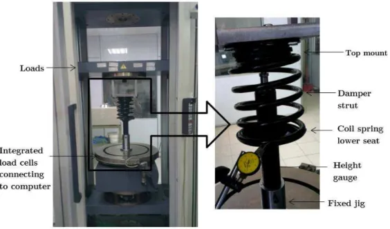
setup for the measurement is similar to the simulation configuration to obtain the representative results. The top mount of the spring damper Macpherson strut was attached to the load tester, and the bottom of the shock absorber was fixed to the ground through the jig. A displacement of 186 mm was imposed from the top of the load tester to compress the actual coil spring into fully com-pressed condition. Loads of 3250 N were obtained when the displacement was applied. The spring stiffness is 17.5 N/mm. A height gauge was used to measure the maximum deflection point. The maximum deflection point was identified through FE explicit simulation. The reading of the height gauge was recorded manually through visual observation and then compared with the simulation result.
Figure 5:Bead parameters for topography
Figure 6:Experimental displacement measurement setup for coil spring lower seat. Bead angle 60o(max)
Element normal vector
Optimized surface
Baseline surface
4 RESULTS AND DISCUSSION
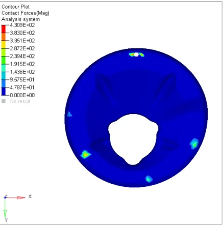
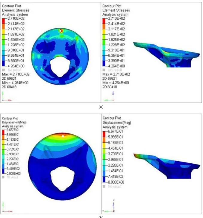
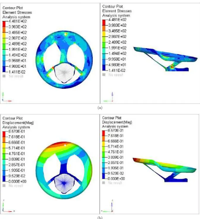
Contact between the coil spring and lower seat was not completely where a few points of contact should be concerned. The contact forces between the coil spring and spring lower seat are shown in Figure 7. Contact forces were transmitted from the coil spring to the spring lower seat when the coil spring was compressed. A maximum force of 431 N was noticed on the spring lower seat. Force loads were mainly distributed at four points of the spring lower seat, which were identified as the contact points. Equivalent force values were converted into linear static analysis for topology and topography optimizations. Figure 8 shows the stress and displacement contour of the lower seat before optimization. This observation indicated that the maximum principal stress of the lower seat was 271 MPa and the displacement was 0.67 mm. Experimental result of height gauge measurement was 0.68 mm. Difference between simulation and experimental measured displacement was only 1.5 %. The current mass of the lower seat is 32.4 g. The stress level of the spring lower is at the limit of the material where the component experiences fatigue failure at short time. Redesigning the lower seat with other high-strength material and minimal material usage model enhances the effi-ciency of the non-optimal design. For topology optimization, applied constraint was compliance where the range was 0.5 ≤ fk(x) ≤ 1.0. The objective function was to minimize mass. In this analysis,
optimization commercial software Altair Optistruct was used. It utilized density based algorithm for topology optimization.
(a)
(b)
Figure 8:Contour plot non-optimal model of (a) element principal stress, (b) displacement.
change and optimization, the most well-known optimization technique, namely, topology optimiza-tion was performed to obtain the stress and displacement for new design. The principal stress and displacement for the topology-optimized model are shown in Figure 8.
(a)
(b)
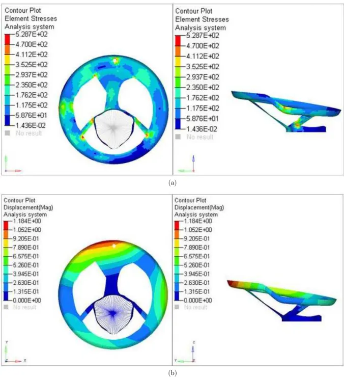
Figure 9:Contour plot Topology optimized of (a) element principal stress, (b) displacement.
design after topology optimization is named as “Topology optimized.” For Topology optimized, the mass of this component is reduced from 32.4 g to 19.2 g. According to calculation, the mass of To-pology optimized has a significant reduction of 41%. However, when coil spring lower seat design Topology optimized is validated for principal stress level and maximum displacement, the new de-sign shows that the maximum principal stress is approximately 529 MPa, which is an increment of 91% of nominal stress value. The displacement of the maximum point also increased from 0.68 mm to 1.18 mm. Based on the stress and displacement outcome, the topology-optimized model was not compatible with the current available steel material, except for the high-strength steel sheet. Mean-while, the deflection of the coil spring lower seat increased to 76% higher than the nominal value. Hence, topography optimization, which intends to enhance the structure stiffness, was performed to enhance design validity.
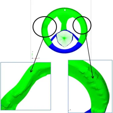
Topography optimization introduces beads into the design to reduce the structural compliance and stress value. The topography-optimized model is named “Topography optimized” in this analysis. The design changes of topography optimization are shown in Figure 10. Beads were added to the left and right portions of support surface. Adding beads resulted in the decrease of the maximum deflec-tion region of the coil spring lower seat. The stress and displacement contours of topography-optimized model are shown in Figure 11. Topography optimization resulted in the reduction of the principal stress value from 529 MPa to 448 MPa. This finding indicated a reduction of 18% in stress value after optimization compared with the finding in Topology optimized. For displacement compari-son, the maximum deflection of the model reduced from 1.18 to 0.86 mm. It is a total reduction of 27% in compliances compared with the result in Topology optimized. As seen from the figure, the model has improved in terms of strength and stiffness. The mass of Topography optimized compared with Topology optimized slightly increased from 19.2 g to 20.5 g because of bead exertion.
(a)
(b)
Figure 11:Contour plot Topography optimized of (a) element principal stress, (b) displacement.
experi-enced when the coil spring is compressed into maximum limit. The maximum stress of design To-pology optimized possesses maximum principal stress of 529 MPa. Hence, the material with tensile strength of at least 539 MPa is selected. The same condition is applied to the material selection process of Topography optimized. The tensile strength of the material must be able to withstand the maximum principal stress level. For displacement aspect, the minimum deformation of the spring lower seat design is preferred because the deflection of the spring lower seat contributes fur-ther to suspension deflection. Meanwhile, anofur-ther design concern is the weight of the component. The weight is minimized through the objective function of topology optimization.
Design Proposed material grade Minimum tensile strength (MPa) Minimum elongations (%)
Non-optimal JIS G 3131 SPHC 270 27
Topology optimized JIS G 3134 SPFH 540 539 21
Topography optimized JIS G 3113 SAPH 440 441 29
Table 2: Mechanical properties of designed materials [28].
Design Proposed Material grade
Maximum principal stress (MPa)
Maximum displacement (mm)
Weight (grams)
Non-optimal SPHC 271 0.68 32.4
Topology optimized SPFH 540 528 1.18 19.2
Topography optimized SAPH 440 448 0.86 20.5
Table 3: Summary of spring lower seat design performance.
5 CONCLUSIONS
In this paper, weight optimization of coil spring lower seat design through the combination of to-pology and topography approaches is presented. Toto-pology optimization has provided the concept by removing the component material while topography enhances the structure stiffness by inducing the beads. The initial design of the coil spring lower seat possesses high stress value; thus, failure may occur after repeated cyclic loading is experienced. Through the combination of topology and topog-raphy optimizations, the coil spring lower seat design has minimized the weight and material usage with the replacement of material. The induction of topographical beads on the component has re-sulted in the strengthening of the lower seat design with minimum acquired material while reducing the mass by 36.5%. The deflection of the new design is small. Therefore, the design is safe from failure. Meanwhile, this optimization has significantly contributed to the design in which no addi-tional material is required. To comply with the current automotive trend, vehicle weight reduction has been achieved to reduce material cost by applying lighter materials into the component model.
Acknowledgements
References
Altair Engineering Inc (2014). Altair User;s Guide, Altair Hyperworks (India).
Bendsoe, M.P. (1995) Optimization of structural topology, shape and material, Springer-Verlag Berlin Heidelberg. Bendsoe, M.P., Kikuchi, N. (1998). Generating optimal topologies in structure design using a homogenization meth-od, Computer Methods in Applied Mechanics and Engineering 71: 197 – 224.
Bendsoe, M.P., Sigmund, O. (1999). Material interpolation schemes in topology optimization, Archive of Applied Mechanics 69: 635 – 654.
Cavazzuti, M., Costi, D., Baldini, A., Moruzzi, P. (2011). Automotive chassis topology optimization: a comparison between Spider and Coupe designs, Proceedings of the World Congress on Engineering (London).
Chakravarty, R. (2009). Study of topography optimization on automotive body structure, SAE technical paper 2009-01-1233.
Chang, S. (2004). Studies of Newmark method for solving nonlinear system: (I) basic analysis, Journal of the Chinese Institute of Engineers 27(5): 651 – 662.
Chiandussi, G, Gaviglio, I, Ibba, A. (2004). Topology optimisation of an automotive component without final volume constraint specification, Advances in Engineering Software 35: 609 – 617.
Chiandussi, G., Fontana, R., Urbinati, F. (1998). Design sensitivity analysis method for multidisciplinary shape optimization problems with linear and non-linear response, Engineering with Computers 15: 391 – 417.
Cui, X., Zhang, H., Wang, S., Zhang, L., Ko, J. (2011). Design of lightweight multi-material automotive bodies using new material performance indices of thin-walled beams for the material selection with crashworthiness consideration, Materials and Design 35: 815 – 821.
Deaton, J.D., Grandhi, R.V. (2014). A survey of structural and multidisciplinary continuum topology optimization: post 2000, Structural and Multidisciplinary Optimization 49(1): 1 – 38.
Deaton, J.D., Grandhi, R.V. (2015). Stress-based design of thermal structures via topology optimization, Structural and Multidisciplinary Optimization: 1 – 18.
Du, X.F., Li, Z.J., Bi, F.R., Zhang, J.H., Wang, X., Shao, K. (2011). Structural topology optimization of engine block to minimize vibration based on sensitivity analysis, Advanced Materials Research 291 – 294: 318 – 326.
Eschenauer, H.A, Olhoff, N. Topology optimization of continuum structures: A review, Applied Mechanics Review 54(4): 331 – 390.
Gillespie, T.D. (1996). Fundamentals of Vehicle Dynamics, Society of Automotive Engineers (U.S.A.).
Gokhale, N.S., Despande S.S., Bedekar S.V., Thite, A.N. (2008). Practical finite element analysis, Finite to Infinite (India).
Grubisic, V. (2006). Determination of load spectra for design and testing, International Journal of Vehicle Design 40: 2 – 14.
Hilber, H.M., Hughes, T.J.R., Taylor, R.L. (1977). Improved numerical dissipation for time integration algorithms in structural dynamics, Earthquake Engineering and Structural Dynamics 5: 283 – 292.
Ishida, T, Hamada, K. Macpherson strut front suspension, US Patent 4,482,135 (Washington). Japanese Standards Association (2003), JIS Handbook Ferrous Materials & Metallurgy II (Japan).
Kane, C., Marsden, J.E., Ortiz, M., West, M. (2000). Variational integrators and the Newmark algorithm for con-servative and dissipative mechanical systems, International Journal for Numerical Methods in Engineering 49: 1295 – 1325.
Kong, Y.S., Omar, M.Z., Chua, L.B., Abdullah, S. (2013). Explicit nonlinear finite element geometric analysis of parabolic leaf springs under various loads, The Scientific World Journal 261926.
Lee, H.P., Sun, J.S., Lee, K.H. Comparison of implicit and explicit finite element methods for dynamic problems, Journal of Materials Processing Technology 105: 110 – 118.
Miller, M.S., Zhuang, L., Bottema, J., Wittebrood, A.J., Smet, P.D., Haszler, A., Vieregge, A. (2000). Recent devel-opment in aluminium alloys for the automotive industry, Materials Science and Engineering A 280: 37 – 49.
Park, G.J. (2004). Equivalent static loads method for non-linear static response structural optimization, LS-DYNA Forum (German).
Querin, Q.M., Steven, G.P., Xie, Y.M. (1998). Evolutionary structural optimization (ESO) using a bi-directional algorithm, Engineering computations 15(8): 1034 – 1048.
Radman, A., Huang, X., Xie, Y.M. (2013). Topological optimization for the design of microstructures of isotropic cellular materials, Engineering optimization 45(11): 1331 – 1348.
Rozvany, G.I.N. (2000). Aims, scope, methods, history and unified terminology of computer aided topology optimiza-tion in structural mechanics, Structural and Multidisciplinary Optimizaoptimiza-tion 21: 90 – 108.
Rozvany, G.I.N. (2009). A critical review of established methods of structural topology optimization, Structural and Multidisciplinary Optimization 37: 217 – 237.
Sakundarini, N., Taha, Z., Abdul Rashid S.H., Raja Ghazila, R.A. (2013). Optimal multi-material selection for lightweight design of automotive body assembly incorporating recycleability, Materials and Design 50: 846 – 857. Sen, A., Londhe, A. (2006) Application of topology and topography optimization in design of FEAD brackets and covers, Altair Users Conference (India).
Xie, Y.M., Steven, G.P. (1993). A simple evolutionary procedure for structural optimization, Computers and Struc-tures 49(5): 885 – 896.
Yu, W.J., Kim, H.C. (1998). Double tapered FRP beam for automotive suspension leaf spring, Composites and Structures 9(4); 279 – 300.
Zhu, F., Guan, F., Zhang, L., Mao, H., Yang, K.H., King, A.I. (2010). Identifying the properties of ultra-soft materi-als using a new methology combined specimen-specific finite element model and optimization techniques, Materimateri-als and Design 31: 4704 – 4712.
Zuo, Z.H., Xie, Y.M., Huang X. (2011). Evolutionary topology optimization of structures with multiple displacement and frequency constraints, Advances in Structural Engineering 15(2): 359 – 372.