Abstract
This paper presents the finite element analysis conducted on SFRP strengthened reinforced concrete (RC) deep beams. The analysis variables included SFRP material (glass and carbon), SFRP thickness (3 mm and 5 mm), SFRP configuration and strength of concrete. The externally applied SFRP technique is significantly effective to enhance the ultimate load carrying capac-ity of RC deep beams. In the finite element analysis, realistic material constitutive laws were utilized which were capable of accounting for the non-linear behavior of materials. The finite element analysis was performed using computer software WCOMD. In the analysis, two dimensional eight-node reinforced concrete planar elements for concrete and planar elements with elastic-brittle behavior for SFRP were used to simulate the physi-cal models. The concept of smeared cracking in concrete and steel was adopted over the element. The calculated finite element re-sults are found to be in good agreement with the experimental results and to capture the structural response of both un-strengthened and SFRP un-strengthened RC deep beams. A compari-son between the finite element results and experimental data proved the validity of the finite element models. Further, the finite element models were utilized to investigate the behavior of RC deep beams strengthened with different directions of SFRP Strips (vertical and horizontal). The vertical SFRP strips are found to be more effective than horizontal ones.
Keywords
Shear strengthening, finite element analysis, RC deep beams, SFRP, WCOMD.
Shear Strengthening of RC Deep Beams with Sprayed
Fiber-reinforced Polymer Composites (SFRP):
Part 2 Finite Element Analysis
Qudeer Hussain a Amorn Pimanmas b
a School of Civil Engineering, Sirindhorn
International Institute of Technology, Thammasat University, Thailand, Email: [email protected]
b Corresponding author: Professor,
Sirind-horn International Institute of Technolo-gy, School of Civil Engineering, Thamma-sat University, Thailand, Email:
[email protected] Tel: (66-2) 986-9009 ext 2403
http://dx.doi.org/10.1590/1679-78251426
Latin A m erican Journal of Solids and Structures 12 (2015) 1266-1295 1 INTRODUCTION
An extensive literature exists on flexural and shear strengthening of reinforced concrete (RC) shal-low beams (Ehsan et al., 2011, Mofidi et al., 2013, Siddiqui et al., 2010). These literature mainly focused on experimental investigation of flexural and shear strengthening of RC beams, using exter-nally bonded uni-directional fiber reinforced polymer composites (FRP). The investigated research parameters were location of fiber, amount of fiber, size of the beam and the flexural reinforcement ratio (Barros et al., 2007, El-Ghandour, 2011, Godat et al., 2010, Rahimi and Hutchinson, 2001). Based on experimental results, it was concluded that externally bonded FRP are significantly effi-cient to alter the behavior of strengthened beams in terms of strength and stiffness (Hawileh et al., 2014, Norris et al., 1997). Further, intensive analytical studies were available for the prediction of load capacity of FRP strengthened RC beams (Rahimi and Hutchinson, 2001, Al-Zaid et al., 2012, Camata et al., 2007, Yang et al., 2003, Supaviriyakit et al., 2004, Rabinovich and Frostig, 2000). In addition, the uni-directional FRP were also proved successful to enhance the shear capacity of RC deep beams (Zhang et al., 2004, Islam et al., 2005, Maaddawy and Sherif, 2009). Despite the suc-cessful application of FRP, the final failure of FRP-strengthened members was reported as brittle failure due to premature de-lamination of FRP from the concrete surface, prior to the full develop-ment of stresses in FRP (Chena and Teng, 2003, Quantrill et al., 1996). Efforts were also put to clarify the bonding mechanisms such as plate-end interface bonding, intermediate crack de-bonding and concrete cover separation (Seracino et al., 2007, Sharma et al., 2006, Smith and Gravina, 2007, Yao et al., 2005). During the last decade, several techniques have been proposed and evaluated to improve the performance of externally bonded FRP, i.e., surface preparation (Toutanji and Ortiz, 2001), end anchorage (Mofidi et al., 2011, Zhang and Smith, 2012), addition of FRP around the beam (Pimanmas and Pornpongsaroj, 2004), the use of end wrapping materials (Grace et al., 1999), externally bonded reinforcement on grooves (EBROG) (M”st” “ejad a“d Shameli,
2013, M”st” “ejad a“d Mahm”udabadi, 2010) and near surface mounted (NSM) method over FRP
(Barros and Fortes, 2005). Almost all investigated methods were reported as successful to improve load carrying capacity of strengthened beams by delaying or postponing the de-bonding of FRP. In contrast to the uni-directi”“al FRP, a“”ther tech“ique Sprayed Fiber Reinforced Polymer
anchor-Latin A m erican Journal of Solids and Structures 12 (2015) 1266-1295
age systems to improve the bond between SFRP and the concrete surface. Based on experimental results, it was concluded that SFRP are significantly effective to enhance the behavior of strength-ened RC deep beams providing that adequately anchoring systems are installed. The present study is primarily focused on the development of nonlinear finite element analysis for RC deep beams strengthened with SFRP. Further, the finite element analysis is then employed as a tool to investi-gate the behavior of RC deep beams strengthened with externally bonded SFRP strips.
2 SUMMARY OF EXPERIMENTAL PROGRAM
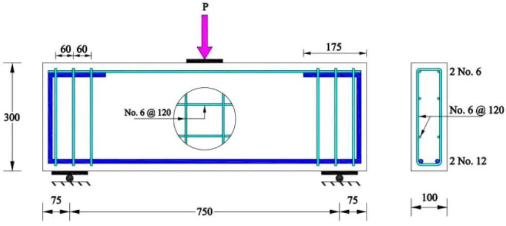
Figure 1, shows the sketch of a typical RC deep beam specimen used in experimental investigation. The RC deep beams were designed in such a way to develop shear failure. The bottom steel bars were 2-DB12 (Yield strength = 410 MPa) and shear reinforcements were RB6 plain bars (yield strength = 240 MPa). The RC deep beams were cast using low strength (21.45 MPa) and high strength concrete (46.20 MPa). The casting of RC deep beams was performed in a vertical position.
Figure 1: Details of test specimen (units in mm).
Latin A m erican Journal of Solids and Structures 12 (2015) 1266-1295
Pimanmas (2014). The mechanical properties of both glass SFRP, and carbon SFRP were deter-mined by tensile strip tests and are listed in Table 1.
Figure 2: Loading set up.
Figure 3: Strengthening Configurations; (a) SFRP configuration A (b) SFRP configuration B.
Latin A m erican Journal of Solids and Structures 12 (2015) 1266-1295 (a)
(b)
(c)
Figure 5: Anchoring systems; (a) TB anchoring system, (b) MB anchoring system, (c) EB anchoring system.
Properties SFRP Units
SGFRP SCFRP
Density 1.47 1.20 g/cm3
Tensile strength 75 84 MPa
Fiber volume fraction 30-40 60-70 %
Table 1: Mechanical properties of SFRP.
3 SUMMARY OF EXPERIMENTAL TEST RESULTS
Latin A m erican Journal of Solids and Structures 12 (2015) 1266-1295
The beam specimen externally strengthened with SFRP with no anchorage failed by a sudden de-bonding of SFRP from concrete surface. The recorded peak load and mid span deflections were similar to the control beam. All three types of investigated anchorage systems were found to be significantly effective to prevent the de-bonding of SFRP from concrete surface. Among these three anchorage systems, TB anchoring system was the most effective; however, the TB anchoring system involved a difficult installation process. The MB and EB anchoring systems are found to be easier to install and are also effective to prevent SFRP de-bonding. In almost all SFRP strengthened and anchored RC deep beams, no de-bonding of SFRP was observed except few beams in which partial de-bonding was observed. The ultimate peak load was found to increase proportionally with the SFRP thickness for both types of SFRP i.e., glass and carbon. The externally bonded SFRP are found to be capable of enhancing the behavior of both low and high strength concrete deep beams providing that SFRPs are adequately anchored onto the surface. A summary of beam specimens, selected from experimental study, for the finite element study is provided in Table 2.
Specimen Finite element
model
Strength of
concrete (MPa) Fiber
SFRP Thickness
Anchoring system
Strengthening configuration
BN-LS-CB FEM-LS-CB 21.45 - - - -
BN-LS-3GA-MB FEM-LS-3GA 21.45 Glass 3 MB A
BN-LS-5GA-MB1 FEM-LS-5GA 21.45 Glass 5 MB A
BN-LS-3CA-MB FEM-LS-3CA 21.45 Carbon 3 MB A
BN-LS-5CA-MB FEM-LS-5CA 21.45 Carbon 5 MB A
BN-HS-CB FEM-HS-CB 46.20 - - - -
BN-HS-3GA-EB FEM-HS-3GA 46.20 Glass 3 EB A
BN-HS-5GA-MB FEM-HS-5GA 46.20 Glass 5 MB A
BN-HS-5GB-MB FEM-HS-5GB 46.20 Glass 5 MB B
Table 2: Summary of experimental program and finite element models.
4 FINITE ELEMENT MODELING
investi-Latin A m erican Journal of Solids and Structures 12 (2015) 1266-1295
gate the behavior of RC deep beams strengthened with different configurations of SFRP strips (ver-tical and horizontal). Typical finite element models are shown in Figures 6. The RC deep beams are modeled using two dimensional eight-node reinforced concrete planer elements. The smeared cracking approach has been assumed in the modeling of concrete and steel. The SFRP is modeled by planar elements with elastic brittle properties (Pimanmas, 2010). Since, no de-bonding of SFRP was occurred in RC deep beams strengthened with SFRP, and anchored with bolts (Hussain and Pimanmas, 2014), therefore in finite element analysis SFRP are modeled assuming perfect bonding between SFRP and concrete. The constitute laws of concrete and steel bars, used in finite element analysis are briefly explained in the next section.
Figure 6(a): Finite element model FEM-LS-CB .
Latin A m erican Journal of Solids and Structures 12 (2015) 1266-1295 Figure 6(c): Finite element model of SFRP strengthened RC deep beam (Strengthening configuration B)
Figure 6: Typical finite element models
4.1 Constitutive Models of Concrete and Reinforcing Bars
A detailed description of the general formation of reinforced concrete planar element is available in the literature (Rashid et al., 1968, De Borst and Nauta, 1985, Bazant and Ozbolt, 1996, Vecchio, 1986, Bazant and Planas, 1997, Riggs and Powell, 1986, Okamura and Maekawa, 1991, Maekawa et al., 2003); therefore it is omitted in this paper. Here, a brief outline of constitutive models is pre-sented, to show the key material behaviors. Further details can be found in the study (Okamura and Maekawa, 1991, Maekawa et al., 2003).
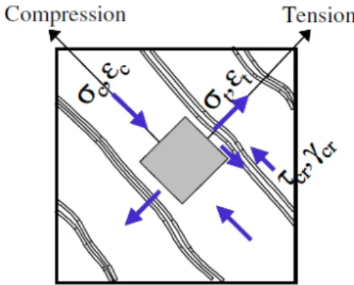
4.1.1 Cracked Concrete Model
The constitutive model of cracked concrete is shown in Figure 7, which is formulated with respect to the crack axis. The model comprised compressive stress model parallel to the crack, tensile stress model orthogonal to crack and shear stress model along the crack face. A single model is formulated by combining tensile and compressive stress models. The relevant constitutive laws are described below.
Latin A m erican Journal of Solids and Structures 12 (2015) 1266-1295
4.1.1.1 Combined Tension Compression Model for Normal Stress Orthogonal and Parallel to a Crack
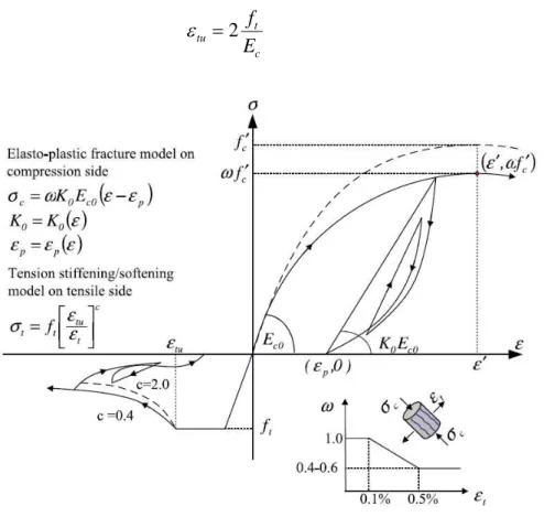
The combined tension-compression model for normal stress orthogonal and parallel to a crack is presented in Figure 8. On the tension side, the model is essentially linear up to the tensile strength of concrete followed by a constant tensile stress until concrete cracks. The tensile post-cracking behavior can be expressed by the following equation;
c
t tu t
t
f
(1)Where tis tensile stress normal to crack, ft is the tensile strength of concrete, t is tensile strain,
tu
is cracking strain which can be calculated using expression (2) and parameter c represents a drop in tensile stress after concrete cracking. In this study; the value of c is set different for plain and reinforced concrete i.e., 2.0 and 0.4, respectively (Maekawa et al., 2003). The higher value of c represents a more sudden drop in tensile stress of concrete. The area under the softening curve of the stress–strain law describes a fracture energy required to propagate a crack. It is an important characteristics of concrete for simulating the crack propagation and localized failure.
c t tu
E
f
2
(2)Latin A m erican Journal of Solids and Structures 12 (2015) 1266-1295
On the compression side, the elsto-plastic fracturing model (Okamura and Maekawa, 1991, Maeka-wa et al., 2003) Maeka-was used to calculate the compressive stress parallel to a crack. The model is capa-ble of combining the non-linearity of plasticity and fracturing damages to account for the perma-nent deformation and loss of elastic strain energy capacity. The relation between compressive stress and strain can be written as;
t p
co
t
K
E
0
(3)
Wheret is the compressive stress parallel to the crack, K0 is the fracture parameter representing
the continuum damage as a result of dispersed cracking in concrete, Ecois the initial elastic modulus
and pis the compressive plastic strain. The plastic compressive strain and fracture parameter are
empirically formulated (Okamura and Maekawa, 1991) as;
25
.
1
exp
1
73
.
0
exp
0K
(4)
1
exp
0
.
35
7
20
2
p (5)
An additional damage factor is incorporated in the model (Equation 3) to consider reduced com-pressive stress due to transverse tensile strain. Figure 8 also shows graphical relation between dam-age factor and transverse tensile strain.
4.1.1.2 Shear Stress Transfer Model
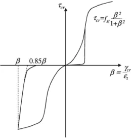
In reinforced concrete, the crack is assumed to form once the principal tensile stress exceeds the tensile strength of concrete. At the instant of cracking, shear stress and strain are zero at the prin-cipal planes. As loading proceeds, the prinprin-cipal axes of stress and strain change, thus imposing shear stress and strain on the cracks generated in the previous load step. For computing shear stress transmitted along a crack face, the contact density model (Okamura and Maekawa, 1991, Maekawa et al., 2003) is adopted (Figure 9). The equation of the shear envelope can be expressed as;
2 2 3 1
1
)
(
8
.
3
ccr
f
(6)Where is the normalized shear strain which can be defined as;
t cr
(7)Latin A m erican Journal of Solids and Structures 12 (2015) 1266-1295 Figure 9: Shear stress transfer model.
Figure 10: Model of steel bar.
4.1.2 Model of Reinforcing Steel Bar
Latin A m erican Journal of Solids and Structures 12 (2015) 1266-1295
first yield of an embedded steel bar occurs at crack locations and afterwards yielding extends to other regions. Thus, it can be assumed that the embedded bar yields at an average stress lower than the nominal yield strength. The average yield strength of embedded steel bars can be comput-ed using the following expression (Salem and Maekawa, 2002).
2
t y y
f
f
f
(8)y
f is the average yield strength of embedded steel bar in concrete, fyis the yield strength of bare
steel bar, ft is the tensile strength of concrete and is the reinforcement ratio. The middle part of
the model is composed of a straight line which joins the average yield point to the 12y,1.1fy point.
Whereas the final part of the model follows the model of bar steel bars up to the final steel rupture point.
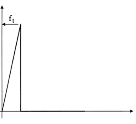
4.2 Constitutive Model of SFRP
Pimanmas (2010) has modeled FRP rods by assuming a linear behavior up to tensile strength. The same concept is adopted here and the constitutive model of SFRP is assumed linear up to the ten-sile strength of SFRP. Once tenten-sile strength is reached, the stress is completely released to zero as shown in Figure 11.
Figure 11: SFRP stress strain model
5 FINITE ELEMENT SIMULATION OF TEST RESULTS
Latin A m erican Journal of Solids and Structures 12 (2015) 1266-1295
5.1 Load Capacity and Deflection Behavior
The predicted load versus mid span deflection curves and cracking patterns are compared with ex-perimental results (Figures 12-20) of selected beam specimens. A detailed summary of predicted finite element results along with the experimental values is presented in Table 3. It can be seen that there is an excellent agreement between the experimental and finite element results until failure. The finite element models can accurately predict the behavior of un-strengthened and SFRP strengthened RC deep beams. The predicted load versus mid span deflection curves are also found to be in good agreement, both for low and high strength concrete RC deep beams. The finite ele-ment models are also capable of predicting the increase in the ultimate load carrying capacity of SFRP strengthened RC deep beams with an increase in SFRP thickness. Both carbon and glass SFRP strengthened RC deep beams can be well simulated. This clearly validates the accuracy and reliability of finite element models.
5.2 Cracking Pattern
The finite element program WCOMD is capable of predicting cracks at every load step. The crack patterns of RC deep beams observed during the experiment and the predicted finite element results are compared in Figures 21. A good match between the observed and predicted crack patterns can be seen. Similar to the experimental results, finite element analysis predicts large diagonal shear cracks in the shear span similar to the experiment.
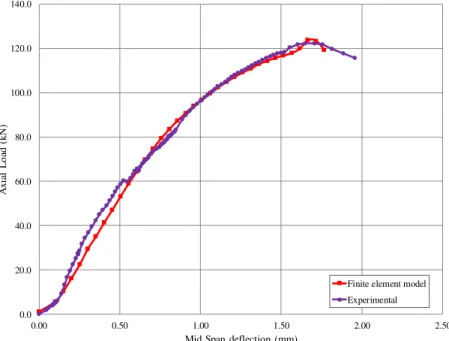
Figure 12: Experimental versus finite element model for beam BN-LS-CB and FEM-LS-CB. 0.0
20.0 40.0 60.0 80.0 100.0 120.0 140.0
0.00 0.50 1.00 1.50 2.00 2.50
A
x
ia
l
L
o
ad
(k
N
)
Mid Span deflection (mm)
Finite element model
Latin A m erican Journal of Solids and Structures 12 (2015) 1266-1295 Figure13: Experimental vs. finite element model for beam BN-LS-3GA-MB and FEM-LS-3GA.
Figure 14: Experimental vs. finite element model for beam BN-LS-5GA-MB1 and FEM-LS-5GA. 0.0 20.0 40.0 60.0 80.0 100.0 120.0 140.0 160.0 180.0 200.0 220.0
0.0 0.5 1.0 1.5 2.0 2.5
A x ia l L o ad (k N )
Mid Span deflection (mm)
Finite element model
Experimental 0.0 20.0 40.0 60.0 80.0 100.0 120.0 140.0 160.0 180.0 200.0 220.0 240.0 260.0 280.0 300.0
0.0 0.5 1.0 1.5 2.0 2.5
A x ia l L o ad (k N )
Mid Span deflection (mm)
Finite element model
Latin A m erican Journal of Solids and Structures 12 (2015) 1266-1295
Figure 15: Experimental vs. finite element model for beam BN-LS-3CA-MB and FEM-LS-3CA.
Figure16: Experimental vs. finite element model for beam BN-LS-5CA-MB and FEM-LS-5CA. 0.0 20.0 40.0 60.0 80.0 100.0 120.0 140.0 160.0 180.0 200.0 220.0 240.0
0.0 0.5 1.0 1.5 2.0 2.5
A x ia l L o ad (k N )
Mid Span deflection (mm)
Finite element model
Experimental 0.0 20.0 40.0 60.0 80.0 100.0 120.0 140.0 160.0 180.0 200.0 220.0 240.0 260.0 280.0 300.0
0.0 0.5 1.0 1.5 2.0 2.5
A x ia l L o ad (k N )
Mid Span deflection (mm)
Finite element model
Latin A m erican Journal of Solids and Structures 12 (2015) 1266-1295 Figure 17: Experimental vs. finite element model for beam BN-HS-CB and FEM-HS-CB.
Figure 18: Experimental vs. finite element model for beam BN-HS-3GA-EB and FEM-HS-3GA. 0.0 20.0 40.0 60.0 80.0 100.0 120.0 140.0 160.0 180.0 200.0 220.0
0.0 0.5 1.0 1.5 2.0 2.5
A x ia l L o ad (k N )
Mid Span deflection (mm)
Finite element model Experimental 0 25 50 75 100 125 150 175 200 225 250 275 300
0.0 0.5 1.0 1.5 2.0 2.5 3.0
A x ia l L o ad (k N )
Mid Span deflection (mm)
Finite element modeling
Latin A m erican Journal of Solids and Structures 12 (2015) 1266-1295
Figure 19: Experimental vs. finite element model for beam BN-HS-5GA-MB and FEM-HS-5GA.
Figure 20: Experimental vs. finite element model for beam BN-HS-5GB-MB and FEM-HS-5GB. 0.0 40.0 80.0 120.0 160.0 200.0 240.0 280.0 320.0 360.0 400.0 440.0
0.00 0.50 1.00 1.50 2.00 2.50 3.00 3.50 4.00
A x ia l L o ad (k N )
Mid Span deflection (mm)
Finite element model
Experimental 0.0 50.0 100.0 150.0 200.0 250.0 300.0 350.0 400.0 450.0 500.0 550.0
0.00 0.50 1.00 1.50 2.00 2.50 3.00 3.50 4.00
A x ia l L o ad (k N )
Mid span deflection (mm)
Latin A m erican Journal of Solids and Structures 12 (2015) 1266-1295 Figure 21(a): Finite element model FEM-LS-CB.
Figure 21(b): Beam BN-LS-CB.
Figure 21(c): Finite element model FEM-HS-CB.
Figure 21(d): Beam BN-HS-CB
Latin A m erican Journal of Solids and Structures 12 (2015) 1266-1295 6 DISCUSSION ON FINITE ELEMENT ANALYSIS RESULTS
6.1 Finite Element Models of Un-strengthened Low and High Strength Concrete RC Deep Beams
From Table 3 and figures 12 & 17, it can be seen that finite element models can well predict the ultimate load carrying capacity and mid span deflection of un-strengthened low and high strength RC deep beams, respectively. The ultimate load carrying capacity calculated by the finite element analyses were recorded as 1.20% and 1.40% higher than the measured values for low and high strength beams, respectively. The mid-span deflection of the finite element model FEM-LS-CB was recorded 1.20% higher than the experimental result, whereas the mid span deflection of the finite element model FEM-HS-CB was 1.10% lower than experimental one. A slight difference between the predicted and measured values for both ultimate load and mid span deflections endorse the validity of the finite element models to predict the behavior of un-strengthened RC deep beams.
6.2 Finite Element Models for Glass SFRP Strengthened Low Strength RC Deep Beams
The predicted load versus mid span deflection curves of glass SFRP strengthened RC deep beam models are shown in Figures 13 and 14 and the results are summarized in Table 3. The predicted ultimate load carrying capacities of the finite element models strengthened with glass SFRP were in good agreement with values recorded experimentally. The ultimate load predicted by the finite ele-ment models for beams strengthened with 3 mm and 5 mm thick SGFRP was found to be only 2.40% and 1.60% higher than experimentally recorded values, respectively. However, the finite element models of was found to overestimate the mid span deflections. The predicted mid span deflections by the finite element models FEM-LS-3GA and FEM-LS-5GA are found to be 8.10% and 3.40%, respectively, higher than the experimental ones. Although the predicted mid span de-flections are slightly higher than the experimentally recorded values, it can be stated that the over-all behavior of strengthened specimens can be well simulated by the finite element models.
Specimen Finite element
model (FEM)
Failure Load (kN) Percentage
Difference
Deflection (mm) Percentage
Difference
Exp. FEM Exp. FEM
BN-LS-CB FEM-LS-CB 122.27 123.70 1.20 1.65 1.67 1.20
BN-LS-3GA-MB FEM-LS-3GA 190.46 195.00 2.40 1.85 2.00 8.10
BN-LS-5GA-MB1 FEM-LS-5GA 248.53 252.41 1.60 2.34 2.42 3.40
BN-LS-3CA-MB FEM-LS-3CA 221.66 217.50 -1.90 1.90 1.87 -1.60
BN-LS-5CA-MB FEM-LS-5CA 274.7 276.30 0.60 2.10 2.05 -2.40
BN-HS-CB FEM-HS-CB 196.35 199.10 1.40 1.92 1.90 -1.10
BN-HS-3GA-EB FEM-HS-3GA 284.57 283.50 -0.40 2.45 2.50 2.05
BN-HS-5GA-MB FEM-HS-5GA 400.25 406.16 1.50 3.54 3.45 -2.54
BN-HS-5GB-MB FEM-HS-5GB 493.18 483.95 -1.90 3.06 3.00 -1.96
Latin A m erican Journal of Solids and Structures 12 (2015) 1266-1295
6.3 Finite Element Models for Carbon SFRP Strengthened Low Strength RC Deep Beams
From Table 3 and Figures 15 and 16, it can be seen that the finite element model tended to slightly underestimate the load capacity and mid span deflection of the RC deep beam specimen strength-ened with 3 mm thick carbon SFRP. The predicted ultimate load and the mid span deflection of the carbon SFRP strengthened FEM model FEM-LS-3CA were 1.90% and 1.60% lower than those recorded during the experiment. However the finite element slightly overestimates the ultimate load of 5 mm thick carbon SFRP strengthened specimen. The ultimate load was 0.60% higher than the experimental value. Similar to the finite element model FEM-LS-3CA, the predicted mid-span de-flection of the FEM model FEM-LS-5CA was lower than the experimental value, in this case around 2.4%. This difference in the prediction of the ultimate load and deflection is considered to be slight and it can be said that the finite element model can reasonably reproduce the experimental results.
6.4 Finite Element Models for Glass SFRP Strengthened High Strength RC Deep Beams
The comparison of finite element and experimental load versus mid span deflections of high strength RC deep beams strengthened with glass SFRP is illustrated in Figures 18-20. A good com-parison can be seen. The ultimate load and mid span deflections can be satisfactorily predicted by the finite element analysis. The ultimate load of the finite element model FEM-HS-5GA was 1.50% higher than the experimental value, whereas only 0.40% and 1.90% decrease in the prediction of the ultimate loads were found for finite element models FEM-HS-4GA and FEM-HS-5GB, respectively. The mid span deflection of the model FEM-LS-5GA was only 2.10% higher than the experimentally recorded value, whereas only 2.60% and 1.96% decrease in the prediction of mid span deflection were observed for the finite element models FEM-HS-5GA and FEM-HS-5GB, respectively. Alt-hough some small discrepancies were observed between predicted and experimental values, it can be concluded that the presented finite element models are well capable of providing reasonable predic-tions for glass SFRP strengthened high strength RC deep beams.
7 EFFECT OF SFRP STRIPS
In the previous section, the finite element analysis was performed for the tested beams and the ana-lytical results were compared with the experimental ones. It can be seen that the present finite ele-ment models are capable of efficiently reproduce the load-mid span deflections, crack pattern and the failure modes. In this section, the finite element model has been adopted to further parametri-cally examine the behavior of low strength RC deep beams strengthened with various forms SFRP strips.
Latin A m erican Journal of Solids and Structures 12 (2015) 1266-1295
element models of RC deep beams strengthened with SFRP strips are presented in Figure 23. De-tailed summary of predicted finite element results is presented in Table 4.
Specimen FEM-LS-V01
Specimen FEM-LS-V02
Specimen FEM-LS-H01
Specimen FEM-LS-H02
Latin A m erican Journal of Solids and Structures 12 (2015) 1266-1295 Finite element model FEM-LS-V01
Finite element model FEM-LS-V02
Finite element model FEM-LS-H01
Finite element model FEM-LS-H02
Latin A m erican Journal of Solids and Structures 12 (2015) 1266-1295
7.1 Effect of Direction
It has been observed experimentally that externally bonded SFRP are effective to enhance the shear capacity of RC deep beams providing that the SFRP is adequately anchored to the beam surface. Although placing SFRP in strips may pose some strengthening difficulty, however, the application of SFRP in strips may result in a reduced material cost compared with SFRP applied on the full surface of RC beams. The finite element analysis is conducted to examine the influence of the direc-tion of SFRP strips. The comparison of load-mid span deflecdirec-tion of both direcdirec-tions (vertical and horizontal) is shown in Figure 24. It can be seen from the analysis results that the vertical SFRP strips are more effective and yields a higher capacity, whereas the beam with horizontal SFRP strips has lower loading capacity and fails by shear failure. This is because the vertical SFRP strips limit the opening of diagonal cracks and finally result in an enhanced shear transfer. The compari-son of finite element crack pattern for both SFRP directions is shown in Figure 27. In the beam with vertical SFRP strips, the inclined cracks are seen not active in the shear span, whereas in beam with horizontal SFRP strips, the FEM model predicts the inclined cracks concentrated in the shear span. In the beam with vertical SFRP strips, vertical flexure cracks are observed near the mid span instead, indicating the yielding of main flexural steel bars. This demonstrates the efficiency of SFRP vertical strips on the suppression of inclined shear cracks.
Figure 24: Effect of SFRP strip direction.
0.0 20.0 40.0 60.0 80.0 100.0 120.0 140.0 160.0
0.0 0.5 1.0 1.5 2.0 2.5 3.0 3.5
A
x
ia
l
L
o
ad
(k
N
)
Mid Span deflection (mm)
Latin A m erican Journal of Solids and Structures 12 (2015) 1266-1295
7.2 Effect of Vertical SFRP Strip Width and Spacing
This analysis is further conducted to investigate the effect of width of the vertical SFRP strips on the behavior of RC deep beams. The load versus mid span deflection behaviors of both finite ele-ment models strengthened with SFRP strips, i.e. FEM-LS-V01 and FEM-LS-V02 along with the control beam are shown in Figure 25. A smaller width, but closer spacing of SFRP vertical strips (i.e., model V01) results in a higher peak load compared with the beam model FEM-LS-V02 with larger strip width but more distant spacing. In Figure 25, a 16.60% and 22.70% increase in the ultimate load was found for the finite element models FEM-LS-V01 and FEM-LS-V02, re-spectively. Since the SFRP strips with smaller widths were more closely spaced over the shear span, thus leaving smaller space for the inclined shear cracks to develop. As a result, inclined shear cracks in the shear span becomes inactive, promoting the development of flexural cracks at the mid span with the higher ultimate load instead (Figure 27). As for the beam model FEM-LS-V02, the space between adjacent strips is larger, allowing the development of some inclined cracks together with the flexural cracks at the mid span (Figure 27). The mid span deflection of both beams was found to be similar. A 91.50 % increase in the mid span deflection was recorded with both widths of SFRP strips.
Figure 25: Effect of SFRP strip width and spacing
0.0 20.0 40.0 60.0 80.0 100.0 120.0 140.0 160.0
0.0 0.5 1.0 1.5 2.0 2.5 3.0 3.5
A
x
ia
l
L
o
ad
(k
N
)
Mid Span deflection (mm)
Latin A m erican Journal of Solids and Structures 12 (2015) 1266-1295
Specimen Failure
Load (KN)
Percentage increase
Mid span deflection (mm)
Percentage increase
BN-LS-CB 122.27 - 1.65 -
FEM-LS-V01 143.80 17.60 3.16 91.50
FEM-LS-V02 150.01 22.70 3.16 91.50
FEM-LS-H01 131.77 7.80 1.67 1.21
FEM-LS-H02 144.54 18.20 1.78 7.80
Table 4: Summary of finite element analysis results.
7.3 Effect of Position of Horizontal SFRP Strips
The finite element analysis is also performed to investigate the effect of position of horizontal SFRP strips. Unlike vertical strips, here the width of horizontal SFRP strips was kept constant, but the position was changed and one more strip was added as shown in Figure 22. The load versus mid span deflection curves of both beams i.e. FEM-LS-H01 and FEM-LS-H02 are shown in Figure 26 along with the control beam BN-LS-CB. It can be observed that the beam FEM-LS-H01 with two horizontal strips results in a lower load carrying capacity than the beam FEM-LS-H02 with three SFRP strips. In Figure 26, 7.80% and 18.20% increase in the ultimate load over the control beam were observed for finite element models with two and three SFRP strips, respectively. This result indicates that the area near the centroid of the cross section is essential for the development of in-clined shear cracks. In the beam model FEM-LS-H02, this area is covered by the central strip, thus disabling the propagation of shear cracks in this area. As a result, the increase in the ultimate is higher than beam model FEM-LS-H01 where there is no horizontal SFRP strip covering this area.
Figure 26: Effect of SFRP strip position.
0.0 20.0 40.0 60.0 80.0 100.0 120.0 140.0 160.0
0.0 0.5 1.0 1.5 2.0 2.5 3.0 3.5
A x ia l L o ad (k N )
Mid Span deflection (mm)
Latin A m erican Journal of Solids and Structures 12 (2015) 1266-1295 Finite element model FEM-LS-V01
Finite element model FEM-LS-V02
Finite element model FEM-LS-H01
Finite element model FEM-LS-H02
Latin A m erican Journal of Solids and Structures 12 (2015) 1266-1295 8 CONCLUSIONS
An analytical investigation on RC deep beams of low and high strength concrete strengthened with externally bonded SFRP has been presented. The analytical results are compared with experimental ones to verify the suitability of finite element models. The finite element analysis results are found to be in good agreement with experimental results for both low and high strength concrete RC deep beams. The finite element models are also capable of simulating the behavior of RC deep beams strengthened with glass and carbon fibers. The analytical models successfully show the crack propa-gation and failure modes of RC deep beams. In beam with discrete SFRP strips, the analytical model demonstrates that vertical SFRP strips are more effective to control shear failure, thus pro-moting the beams to fail by a more desirable flexural failure mode. The vertical SFRP strips are shown to be more effective than horizontal SFRP strips, especially if they are distributed at closer spacing. It is also found that the SFRP horizontal strips provided close to the centroid of the beam is significantly effective to increase the load carrying capacity of RC deep beams.
Acknowledgements
The authors are very grateful to the Thailand Research Fund (TRF) for providing the grant No. BRG5680015 to carry out the research. A partial financial support from the National Research University Project of Thailand Office of Higher Education Commission was also acknowledged.
References
Alsayed, S.H., Siddiqui, N.A., (2013). Reliability of shear-deficient RC beams strengthened with CFRP-strips. Con-struction and Building Materials 42: 238–247.
Al-Zaid, R.Z., Al-Negheimish, A.I., Al-Saawani, M.A., El-Sayed, A.K., (2012). Analytical study on RC beams strengthened for flexure with externally bonded FRP reinforcement. Composites: Part B: Engineering 43(2): 129-141. Banthia, N., Boyd, A.J., (2000). Sprayed fiber-reinforced polymers for repairs. Canadian Journal of Civil Engineering 27(5): 907-915.
Banthia, N., Yan, C., Nandakumar, N., (1996). Sprayed fibre reinforced plastics (FRPs) for repair of concrete struc-tures. In Proceedings of the 2nd International Conference on Advanced Composite Materials in Bridges and Struc-tures, ACMBS-II, Montreal.
Barros, J.A., Dias, S.J., Lima, J.L., (2007). Efficacy of CFRP-based techniques for the flexural and shear strengthen-ing of concrete beams. Cement and Concrete Composites 29(3): 203–217.
Barros, J.A., Fortes, A.S., (2005) Flexural strengthening of concrete beams with CFRP laminates bonded into slits. Cement Construction Composites 27(4): 471-480.
Bazant, Z.P., Ozbolt, J., (1996). Numerical smeared fractural analysis: nonlocal microcrack interaction approach. International Journal for Numerical Methods in Engineering 39: 635–661.
Bazant, Z.P., Planas, J. (1997). Fracture and size effect in concrete and other quasibrittle materials. CRC Press 16. Boyd, A.J., (2000). Rehabilitation of reinforced concrete beams with sprayed glass fiber reinforced polymers. Ph.D. Thesis, University of British Columbia, Vancouver, Canada.
Latin A m erican Journal of Solids and Structures 12 (2015) 1266-1295 Camata, G., Spacone, E., Zarnic. R., (2007). Experimental and nonlinear finite element studies of RC beams strengthened with FRP plates. Composites: Part B: Engineering 38(2): 277–288.
Chena, J.F. and Teng, J.G., (2003). Shear capacity of FRP-strengthened RC beams: FRP debonding. Construction and Building Materials 17(1): 27-41.
De Borst, R., Nauta, P., (1985). Non orthogonal cracks in smeared finite element models. Engineering Computations 2(1): 35-46.
Dong, J.F., Wang, Q.Y., Guan, Z.W., (2012). Structural behaviour of RC beams externally strengthened with FRP sheets under fatigue and monotonic loading. Engineering Structures 41: 24-33.
Ehsan, A., Habibur, R.S., Norsuzailina, M. S., (2011). Flexural performance of CFRP strengthened RC beams with different degrees of strengthening schemes. International Journal of the Physical Sciences 6(9): 2229-2238.
El-Gha“d”ur, A.A., (2011). Experime“tal a“d a“alytical i“vestigati”“ ”f CFRP exural a“d shear stre“gthe“i“g ef cie“cies ”f RC beams. C”“structi”“ a“d Buildi“g Materials 25(3): 1419-1429.
Godat, A., Qu, Z., Lu, X.Z. Labossiere, P., Ye, L.P., Neale, K.W., (2010). Size Effects for reinforced concrete beams strengthened in shear with CFRP strips. Journal of Composites for Construction 14(3): 260-271.
Grace, N.F., Sayed, G.A., S”lima“, A.K., Saleh, K.R., (1999). Stre“gthe“i“g rei“f”rced c”“crete beams usi“g ber reinforced polymer (FRP) laminates. ACI Structural Journal 96(5): 865-874.
Hawileh, R.A., Rasheed, H.A., Abdalla, J. A., Al-Tamimi. A.K., (2014). Behavior of reinforced concrete beams strengthened with externally bonded hybrid fiber reinforced polymer systems. Materials and Design 53: 972–982. Hussain, Q., Pimanmas, A., (2014). Shear strengthening of RC deep beams with sprayed fiber-reinforced polymer composites (SFRP) and anchoring systems: Part 1. Experimental study. European Journal of Environmental and Civil Engineering (Submitted).
Islam, M.R., Mansur, M.A., Maalej, M., (2005). Shear strengthening of RC deep beams using externally bonded FRP systems. Cement and Concrete Composites 27(3): 413–420.
Kanakubo, T., Furuta, T., Takahashi, K., Nemoto, T., (2005). Sprayed fiber-reinforced polymers for strengthening of concrete structures. In Proceedings of the International Symposium on Earthquake Engineering Commemorating Tenth Anniversary of the 1995 Kobe Earthquake. Kobe, 299-307.
Kwon, K.Y., Yoo, D.Y., Han, S.C., Yoon, Y.S., (2014). Strengthening effects of sprayed fiber reinforced polymers on concrete. Polymer Composites.
Lee, H.K., Hausmann, L.R., (2004). Structural repair and strengthening of damaged RC beams with sprayed FRP. Composites Structures 63(2): 201-209.
Lee, H.K., Hausmann, R.L., Seaman, W.C., (2008). Effectiveness of retrofitting damaged concrete beams with sprayed fiber-reinforced polymer coating. Journal of Reinforced Plastic Composites 27(12): 1269-1286.
Maaddawy, T.E., Sherif, S., (2009). FRP composites for shear strengthening of reinforced concrete deep beams with openings. Composite Structures 89(1): 60-69.
Maekawa, K., Okamura, H., Pimanmas, A., (2003). Nonlinear mechanics of reinforced concrete. CRC Press.
Mofidi, A., Chaallal, O., Benmokrane, B. Neale, K., (2011). Performance of end-anchorage systems for RC beams strengthened in shear with epoxy-bonded FRP. Journal of Composites for Construction 16(3): 322-331.
Mofidi, A., Thivierge, S., Chaallal, O., Shao, Y., (2013). Behavior of reinforced concrete beams strengthened in shear using L-shaped CFRP plates: Experimental Investigation. Journal of Composites for Construction, 18(2).
M”st” “ejad, D., Mahm”udabadi, E., (2010). Gr””vi“g as alter“ative meth”d ”f surface preparati”“ t” p”stp”“e
debonding of FRP laminates in concrete beams. Journal of Composites Construction 14(6): 804–11.
Latin A m erican Journal of Solids and Structures 12 (2015) 1266-1295
Norris, T., Saadatmanesh, H., Ehsani, M.R., (1997). Shear and flexural strengthening of R/C beams with carbon fiber sheets. Journal of Structural Engineering 123(7): 903-911.
Okamura, H., Maekawa, K., (1991). Nonlinear analysis and constitutive models of reinforced concrete. Gihodo, To-kyo.
Pimanmas, A, (2010). Strengthening R/C beams with opening by externally installed FRP rods: Behavior and analy-sis. Composite Structures 92(8): 1957-1976.
Pimanmas, A., Pornpongsaroj, P., (2004). Peeling behaviour of reinforced concrete beams strengthened with CFRP plates under various end restraint conditions. Magazine of Concrete Research 56(2): 73–81.
Quantrill, R.J., Hollaway, L.C., Thorne, A.M., (1996). Experimental and analytical investigation of FRP strength-ened beam response: Part I. Magazine of Concrete Research 48(177): 331-342.
Rabinovich, O., Frostig, Y., (2000). Closed-form high-order analysis of RC beams strengthened with FRP strips. Journal of Composites for Construction 4(2): 65-74.
Rahimi, H., Hutchinson, A., (2001). Concrete beams strengthened with externally bonded FRP plates, Journal of Composites for Construction 5(1): 44-56.
Rashid, Y.R., (1968). Analysis of prestressed concrete reactor vessels. Nuclear Engineering and Design 7: 334-344. Riggs, H.R., Powell, G.H., (1986). Rough crack model for analysis of concrete. Journal of Engineering Mechanics (ASCE) 112(5): 448-464.
Ross, S., Boyd, A., Johnson, M., Sexsmith, R., Banthia, N., (2004). Potential retrofit methods for concrete channel beam bridges using glass fiber reinforced polymer. Journal of Bridge Engineering 9(1): 66-74.
Salem, H., Maekawa, K., (2002). Spatially averaged tensile mechanics for cracked concrete and reinforcement under highly inelastic range. Journal of Materials, Concrete, Structures and Pavements JSCE 42(613): 227-293.
Seracino, R., Raizal Saifulnaz, M.R., Oehlers, D.J., (2007). Generic debonding resistance of EB and NSM plate-to-concrete joints. Journal of Composites Construction 11(1): 62-70.
Sharma, S.K., Ali, M.S.M., Goldar, D., Sikdar, P.K., (2006). Plate-concrete interfacial bond strength of FRP and metallic plated concrete specimens. Composites Part B: Engineering 37(1): 54-63.
Siddiqui, N.A., (2010). Experimental investigation of RC beams strengthened with externally bonded FRP compo-sites. Latin American Journal of Solids and Structures 6(4): 343–362.
Smith, S.T., Gravi“a, R.J., (2007). M”deli“g deb”“di“g failure i“ FRP exurally stre“gthe“ed RC members usi“g a local deformation model. Journal of Composites Construction 11(2): 184-191.
Soleimani, S.M., Banthia, N., (2012). Shear strengthening of RC beams using sprayed glass fiber reinforced polymer. Advances in Civil Engineering 20.
Sundarraja, M.C., Rajamohan, S., (2009). Strengthening of RC beams in shear using GFRP inclined strips – An Experimental study. Construction and Building Materials 23(2): 856–864.
Supaviriyakit, T., Pornpongsaroj, P., Pimanmas, A., (2004). Finite element analysis of FRP-strengthened RC beams. Songklanakarin Journal of Science and Technology 26(4): 497-507.
Teng, J. G., Chen, G. M., Chen, J. F., Rosenboom, O. A., Lam, L., (2009). Behavior of RC beams shear strength-ened with bonded or unbonded FRP wraps. Journal of Composites for Construction 13(5): 394-404.
Toutanji, H., Ortiz, G., (2001). The effect of surface preparation on the bond interface between FRP sheets and concrete members. Composite Structures 53(4): 457-462.
Vecchio, F.J., (1986). Nonlinear finite element analysis of reinforced concrete membranes. ACI Structural Journal 83(1): 26–35.
Latin A m erican Journal of Solids and Structures 12 (2015) 1266-1295 Yang, Z.J., Chen, J.F., Proverbs, D., (2003). Finite element modelling of concrete cover separation failure in FRP plated RC beams. Construction and Building Materials 17(1): 3-13.
Yao, J., Teng, J.G., Chen, J.F., (2005). Experimental study on FRP-to-concrete bonded joints. Composites Part B: Engineering 36(2): 99-113.
Zhang H.W., Smith, S.T., (2012). FRP-to-concrete joint assemblages anchored with multiple FRP anchors. Compo-site Structures 94(2): 403–414.