Abs tract
The lack of lateral resistance in a curved railway track can pro-duce misalignment problems due to the centrifugal forces when the trains pass through. Moreover, most of the times continuous weld-ed rails (CWR) are usweld-ed in nowadays railway tracks, which can induce the track buckling as a result of thermal loads caused by high temperature gradients. A new sleeper has been designed to provide higher lateral resistance of the track. A finite element model has been developed to analyze the lateral movements of an actual curved track subjected to lateral resistance problems. Then, variations on the finite element model have been made to study the response of the track when different sleepers are used. Thus, the performance of the different sleepers in the modeled track has been analyzed, resulting that the inclusion of the new sleeper in the track can improve the lateral resistance between 39 and 55 % with respect to a track with conventional sleepers made of wood or concrete.
Key words
Railway engineering, lateral resistance, curved railway track, new sleeper design, finite element model
Design of a new high lateral resistance sleeper and performance
comparison with conventional sleepers in a curved railway track by
means of finite element models
1 INTRODUCTION
Railway tracks must ensure safe traffic through resisting appropriately the loads they are subjected to. In this regard, track resistance can be divided into four different resistant mechanisms: lateral, longitudinal, torsional and vertical. This paper focuses on the lateral resistance.
The lateral resistance is defined as the reaction offered by the ballast against lateral movement, as stated by Kish (2011). It is well known that this parameter depends on multiple factors related to the ballast interaction, like reported by Emdal (2007). This resistance at the
sleeper-L au ra M on ta lb án Dom in g oa , * Ju li a I. Re al H e rrai zb
C la ra Z am oran oc Te res a Re al H e rra izd
a
Department of Transportation Engineering and Infrastructures, School of Civil Engineer-ing, Polytechnic University of Valencia. 14 Camino de Vera, 46022, Valencia. Spain.
b
Department of Transportation Engineering and Infrastructures, School of Civil Engineer-ing, Polytechnic University of Valencia. 14 Camino de Vera, 46022, Valencia. Spain.
c
Foundation for the Research and Engineering in Railways, 160 Serrano, 28002 Madrid, Spain.
d
Department of Transportation Engineering and Infrastructures, School of Civil Engineer-ing, Polytechnic University of Valencia. 14 Camino de Vera, 46022, Valencia. Spain.
*
Latin American Journal of Solids and Structures 11 (2014) 1238-1250
ballast comes from contact at the base, shoulder and crib. Hence, the high variability of the lateral resistance is influenced by factors such as the weight, shape and material of the sleeper, the ballast grading, the shoulder width, etc.
Regarding the situations where the lateral resistance is important, on the one hand, the horizon-tal curves along the railway tracks should be considered. The train passing through curved railway tracks results in centrifugal forces and thus the lateral resistance mechanisms are activated as a response to those forces, in accordance with Le Pen (2008).
On the other hand, buckling is also a major problem in terms of lateral resistance. In this sense, it should be mentioned that most railway tracks are constructed with continuous welded rails (CWR). Since the earlier bolted rail-ends were found to be a huge source of fatigue failures, increas-ing considerably the maintenance costs, new joinincreas-ing methods were investigated. Thus, in the 1950’s the first welded rails begun to appear in the railway tracks. Nowadays they have become the most used ones due to the improved ride quality, increased rail and rolling stock fatigue life, and reduced maintenance costs, as stated by Skyttebol (2005) and Kish (2013). However, by using the CWR, new problems have arisen related to failure modes caused by thermal loads in the rails. Therefore, as the rail temperature increases, compressive loads are induced in the rail and the track buckling may occur.
Moreover, the combination of curved CWR tracks and compressive loads generated by high temperature variations at the rail increases the importance of the lateral resistance to avoid the lateral track buckling. When the curve degree and the thermal forces are high, and the lateral re-sistance is low, the lateral movements can be large.
In this situation, given a particular curved CWR track subjected to high temperature variations, and a weak lateral restraint, a new sleeper is designed in order to increase the lateral resistance of the track. Then, a comparison of the lateral resistance with different sleepers is carried out by means of the finite element method used to model the given railway track.
2 DESCRIPTION OF THE RAILWAY TRACK STUDIED
A problematic railway track, which is placed in Cantabria (Spain), is analyzed. Then, the proposal of a solution to ensure a safe traffic through the corresponding track is made.
Latin American Journal of Solids and Structures 11 (2014) 1238-1250
Figure 1 Horizontal curves of the railway track studied.
Regarding the materials, the track is not in suitable conditions: the sleepers are made of wood, which are less heavy than the concrete sleepers and mobilizes less friction; the ballast is fouled, filled with finer materials from subgrade soil intrusion. Also, the shoulder width is small. Further-more, the difference of temperature measured at the rail in a single day can be up to 40 ºC. Moreo-ver, the rails are welded forming one uninterrupted rail (CWR). Thus, the low lateral resistance of the track with CWR and the environmental conditions result in large lateral movements.
Given that the lateral strength of the track is not enough to ensure the lateral stability due to the high thermal forces at the rail, this resistance must be increased. The lateral strength could be improved by increasing the shoulder width (Kabo, 2006), but the lack of space prevents it. Also, the ballast bed can be changed by a new one in order to have the suitable ballast quality to provide adequate track lateral resistance (Ryan, 2005). Besides, the lateral resistance can be increased by means of a new design of the sleeper that enhances the frictional behavior of the tie-ballast contact. The scope of this paper is focused on the design of a new sleeper and its influence in terms of track lateral resistance.
3 DESIGN OF THE NEW SLEEPER
A key parameter having a large influence on buckling strength is the sleeper-ballast lateral re-sistance. This resistance has three contributing components, as shown in Figure 2 and indicated by Kish (2011): bottom friction (Fb), side friction (Fs), and end or shoulder restraint (Fe).
Figure 2 Lateral resistance components.
0 2 4 6 8 10 12
0 10 20 30 40 50 60 70 80
X
[
m
]
Z [m]
tangent clothoid circle
clothoid
tangent
F
Fb
Latin American Journal of Solids and Structures 11 (2014) 1238-1250
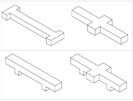
New shapes for the sleepers were proposed to be studied. The designs were based on the addition of prominent wings around the sleeper in order to increase some of the contributing components of the lateral resistance. The four different designs shown in Figure 3 were analyzed.
Figure 3 Perspective view of the four sleepers analyzed.
The wings at the bottom of the sleeper were found to be the more efficient ones to constrain the lateral movements. Besides, the condition of not inconvenience the tamping and maintenance works results in the discard of the solutions that include lateral wings. Therefore, the chosen design corre-sponds to the sleeper with wings only at the bottom, below the rails.
Regarding the size of the wings, it was decided to design a width equal to 14 cm. The influence of the vertical length was investigated concluding that the larger the wing, the higher the lateral resistance, although for just a small difference. However, high wing’s length could cause high stress concentration at the wing-sleeper joint. Thus, a vertical length of 15 cm was set as a compromise solution, as indicated in Figure 4.
Latin American Journal of Solids and Structures 11 (2014) 1238-1250
After the design process, the sleeper was tested. Bending behavior was analyzed according to ADIF (Administrador de Infraestructuras Ferroviarias) rules (ET 03.360.571.8) and European standard EN 13230-2.
4 FINITE ELEMENT MODEL
The aim of this study is to compare the performance of the new sleeper against wood and concrete conventional sleepers in terms of lateral resistance. The analysis for the different railway track set-tings regarding the sleepers must be carried out under the same conditions in order to allow they are comparable between each other.
The recommendations given in Ministerio de Fomento (1999) have been followed to develop the finite element model. The three-dimensional model is built by means of hexahedral elements defined by 20 nodes. The materials are considered isotropic and linear, except the ballast and the founda-tion, which are modeled as a Drucker-Prager material. Then, a description of the main features of the model is shown below.
4.1 Rail modelization
For the sake of simplicity and efficiency, the rail is modeled with a rectangular cross-section. There-fore, the width (w) and height (h) of the modeled rail should be adapted in order to behave the same way that the real rail does. As the axial forces in the rail are the main loads that the railway track is subjected to, the cross-section area of the modeled rail must be equal to the real one. Also, the rail is expected to bend about the vertical axis due to the curved track and the axial forces in the rail, so the moment of inertia about the vertical axis of the modeled rail must be equal to the real one. Thus, the following equations must be satisfied:
A
real =Amodel =w·h (1)
Iy,real =Iy,model = 1 12·h·w
3
(2)
The mechanical values of the real rail (Vignole) are indicated in Table 1 and the Figure 5 shows a sketch of the cross-section.
Table 1 Mechanical properties of the Vignole rail (A = area of the cross-section, Iy = moment of inertia about the vertical axis, Ix =
moment of inertia about the horizontal axis, E = modulus of elasticity of the material, ν = Poisson’s ratio of the material).
Mechanical properties of the Vignole rail
A [cm2] Iy [cm4] Ix [cm4] E [GPa] ν
Latin American Journal of Solids and Structures 11 (2014) 1238-1250 Figure 5 Cross-section of the Vignole rail (dimensions in mm).
Therefore, solving the above system of equations is concluded that the rectangular cross-section of the modeled rail must have a width (w) equal to 7.341 cm and a height (h) equal to 7.772 cm.
4.2 Tie plate modelization
The tie plates, fasteners and anchors have to be capable of preventing the rail running and the rail rotation. Thus, they are modeled as elements which join both the rail and the sleeper.
In case of displaying wood sleepers, rigid fastening system is considered. They are modeled as 13 mm thick steel elements whose mechanical properties are the same as the rail ones.
In case of displaying concrete sleepers, elastic fastening system is modeled. Then, thickness is maintained as 13 mm and mechanical properties are corrected in order to simulate real element compressive stiffness, as indicated by J.Real (2012).
4.3 Sleepers modelization
Three different types of sleepers are considered. Two of them are conventional sleepers, one made of wood and the other one made of concrete; the third type is the new sleeper proposed in this paper. The conventional wood sleeper is a 190x22x13 cm prism shaped element. The material is consid-ered to be linear-elastic with a modulus of elasticity of 13.82 MPa and a Poisson’s ratio of 0.3. The conventional concrete sleeper can be modeled approximately as a prism whose size is 190x26x20 cm. This element is supposed to behave like a linear-elastic material, being the modulus of elasticity equal to 50 MPa and the Poisson’s ratio equal to 0.25.
The new sleeper is sized as the conventional concrete one, but wings at the bottom of the sleeper are added. The wings have a width of 14 cm and a height of 15 cm. The material is considered equal to the conventional concrete sleeper previously mentioned.
Latin American Journal of Solids and Structures 11 (2014) 1238-1250
4.4 Ballast and subgrade modelization
The railway track substructure is mainly composed by two layers: ballast and subgrade. Nowadays there are many material models available in the finite element software packages which are able to set an appropriate behavior to such materials. The elasto-plastic constitutive law based on the Drucker-Prager yield criterion is commonly used to model the substructure layers in railway track finite element modelizations. Therefore, the ballast and subgrade are modeled as elasto-plastic ma-terials obeying the Drucker-Prager criterion. This model requires the next parameters to be estab-lished: the modulus of elasticity, the Poisson's ratio, the cohesion and the internal angle of friction. It should be pointed out that the ballast of the railway track studied was polluted by fines com-ing from the underlycom-ing layer. As the contamination of the ballast increases, the mechanical proper-ties are affected and tend to decrease, as reported by Bernhard (2007). Thus, a ballast bed of poor quality is considered in this study, assuming the following material properties: modulus of elasticity equal to 20 MPa, Poisson’s ratio equal to 0.2, internal angle of friction equal to 35º and null cohe-sion.
Regarding the subgrade layer, the material properties are assumed to be a QS3 soil defined in Ministerio de Fomento (1999): modulus of elasticity equal to 80 MPa, Poisson’s ratio equal to 0.3, internal angle of friction equal to 35º and null cohesion.
4.5 Geometry and mesh
The asymmetry of the geometry of the model prevents to take advantage of any simplification by symmetry. The complete cross-section must be modeled.
The lateral movements at the rail are the needed results to carry out this study. As stress and strains are not a required output, it is desirable not to use a fine mesh at the cross-section level in order to reduce the number of elements in the model, and thus reduce the computation time. Then, the mesh of a cross-section is shown in Figure 6.
Figure 6 Mesh of a cross-section of the railway track.
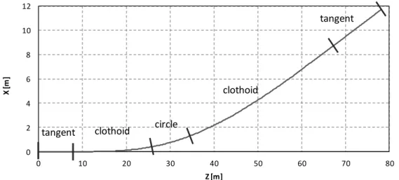
The longitudinal dimension of the track model is characterized by the horizontal curves men-tioned before: tangent, clothoid, circle, clothoid and tangent. The longitudinal discretization is set to one division for the space between sleepers and one division for the sleepers. The Figure 7 shows a perspective view of the complete finite element model.
X Y
Latin American Journal of Solids and Structures 11 (2014) 1238-1250 Figure 7 Perspective view of the finite element model.
4.6 Link and boundary conditions
The link between different materials is set to be adherent, so they share the nodes at the contact surface. Nevertheless, the link between the sleeper and the ballast is not treated in the same way: each material has its own nodes. Therefore, the contact surfaces expected to mobilize the frictional mechanism are modeled by means of contact elements; the contact surfaces of the shoulder restraint and the lower wings restraints subjected to pressure against the ballast are modeled by coupling the perpendicular movement of the nodes of the sleeper and the ballast that are placed at the same geometrical coordinates; the contact surfaces of the sleeper expected to unbound from the ballast do not have any constrain defined, thus the surface is composed by different nodes for each material allowing appropriately the loss of contact between them. The friction coefficient set to the contact elements is equal to 1.15 for the sleeper made of wood and equal to 0.9 for the sleepers made of concrete, as indicated by Kish (2011).
The boundary conditions of the model are set to constrain the perpendicular movement to the edge surface of the nodes that belong to that surface, as recommended in Ministerio de Fomento (1999): movements constrained in the vertical direction of the lower surface, in the transverse direc-tion of the transverse boundaries, and in the longitudinal direcdirec-tion of the longitudinal boundaries.
4.7 Loads
As described above, the thermal loads are capable of producing the buckling of the curved CWR track. Thus, an increment of 40 ºC is applied to the rails in order to compare the lateral resistance in the finite element models with different sleepers.
4.8 Validating the model
It should be mentioned that the finite element model was updated and validated using experimental measures taken from the actual railway track placed in Cantabria (Spain). The test followed con-sisted on measuring existing temperature and lateral displacements at the external rail of the track produced in 7 cross sections. Thus, the maximum displacement produced by the temperature
X
Y
Latin American Journal of Solids and Structures 11 (2014) 1238-1250
changes was obtained. The model showed an appropriate behavior in accordance with the actual track.
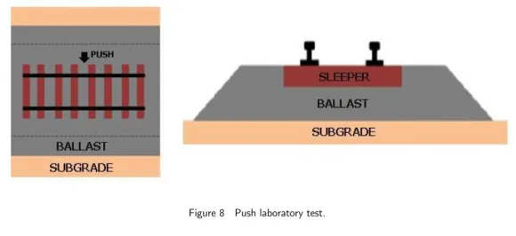
In addition, in order to validate the simulation when friction is mobilized and large displace-ments are produced, laboratory push tests were carried out. These tests consisted on building 8 sleepers track superstructure and pushing the central cross section by mechanical methods, as shown in figure 8. The maximum displacements obtained with each kind of sleeper were determined and the appropriate model behavior was verified. The maximum displacements obtained with these tests were about to 50 mm.
Figure 8 Push laboratory test.
5 RESULTS AND DISCUSSION
These horizontal displacements are related to the lateral resistance of the track: the higher the hori-zontal displacements the lower the lateral resistance. Thus, the horihori-zontal displacements of the rail in the models with different sleepers are compared.
Latin American Journal of Solids and Structures 11 (2014) 1238-1250 Figure 9 Transverse displacements at the track composed by wood sleepers.
Latin American Journal of Solids and Structures 11 (2014) 1238-1250
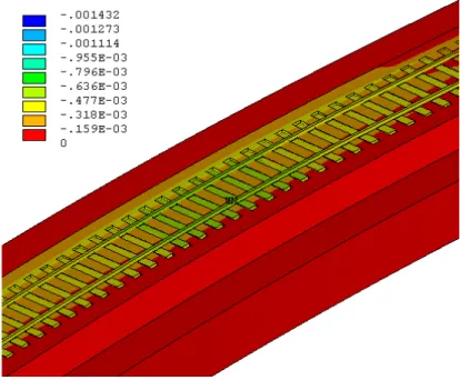
Figure 11 Transverse displacements at the track composed by the new sleepers.
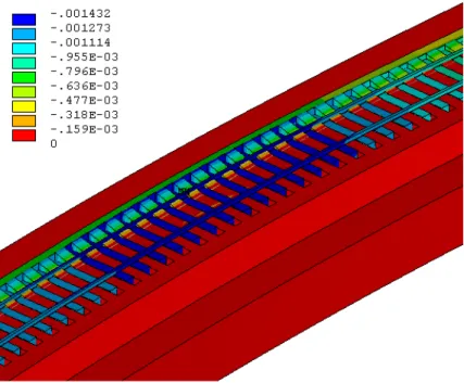
Furthermore, an additional case of study has been proposed where the sleepers are mixed. The new model is based on a different sleeper distribution which consists of a succession of two conven-tional concrete sleepers and one new designed sleeper. The maximum transverse displacement regis-tered is equal to 0.90 mm. Besides, the transverse displacement distribution (see Figure 12) shows, by means of the color grading, how the new sleepers mobilize the surrounding ballast and thus the lateral displacements are reduced.
Latin American Journal of Solids and Structures 11 (2014) 1238-1250
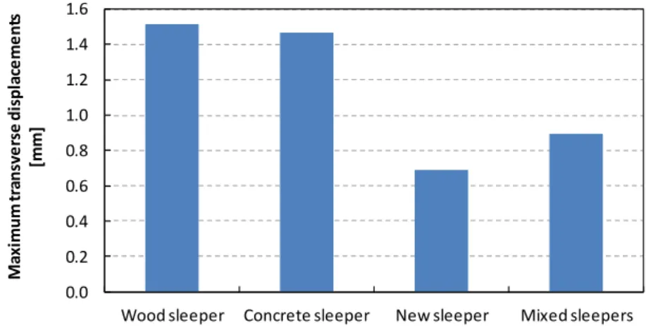
Finally, the maximum transverse displacements of the four track settings are compared in Figure 13. It can be noticed that the best performance in terms of lateral resistance is obtained at the track composed by the new sleepers, which achieves an improvement of a 54.7 % with respect to the con-ventional wood sleeper track, a 53 % with respect to the concon-ventional concrete sleeper track, and a 23.3 % with respect to the mixed sleeper track. Although the track composed by the new sleepers has a better performance than the mixed sleeper track, the last one achieves an improvement of the lateral displacements of a 40.9 % with respect to the conventional wood sleeper track, and a 38.7 % with respect to the conventional concrete sleeper track. It should be pointed out that this mixed configuration can be an interesting solution for reducing the lateral displacements in a track with low lateral resistance, since the use of just one new sleeper every two conventional concrete sleepers can be advantageous with respect to the track composed only by new sleepers in economic terms.
Figure 13 Maximum transverse displacements registered in the four different models proposed.
6 CONCLUSIONS
Given a problematic curved railway track which registers high lateral displacements, a new sleeper has been designed in order mobilize a higher area of the ballast bed and thus increase the lateral resistance of the track.
A finite element model has been developed to test the behavior of different tracks composed by different sleepers. The model takes into account the actual horizontal alignment of the track con-sisting of five segments: tangent, clothoid, circle, clothoid, tangent. Then, the rails of the track have been subjected to thermal loads and the performance of the different tracks proposed has been ana-lyzed, concluding the following remarks:
The new sleeper reduces the lateral displacements registered, achieving an improvement of a 54.7 % with respect to the conventional wood sleeper track, and a 53 % with respect to the conventional concrete sleeper track.
A track composed by one new sleeper every two conventional concrete sleepers has been studied. Although the track formed by the new sleeper has a better performance, the mixed
0.0 0.2 0.4 0.6 0.8 1.0 1.2 1.4 1.6
Wood sleeper Concrete sleeper New sleeper Mixed sleepers
Latin American Journal of Solids and Structures 11 (2014) 1238-1250
sleeper track achieves an improvement of the lateral displacements of a 40.9 % with respect to the conventional wood sleeper track, and a 38.7 % with respect to the conventional con-crete sleeper track. Therefore, this configuration can increase the lateral resistance of the track and, in the meanwhile, can be advantageous in economic terms with respect to a track composed only by the new sleeper.
References
Bernhard W. Lichtberger (2007). Railway track optimisation by efficient track maintenance machinery and strat-egies. Rail Engineering International Edition 2007 Number 4.
Emdal, A.E., Priol, G., Grimstad, G., Lohren, A.H. (2007). Numerical analysis of the effect of sleepers on the lat-eral displacement of railway track. Numerical Models in Geomechanics.
ET 03.360.571.8 (ADIF) (2009). Especificación Técnica. Traviesas de Hormigón Pretensado.
European Standard EN 13230-2. Aplicaciones ferroviarias. Vía. Traviesas y soportes de hormigón. Parte 2: Tra-viesas monobloque pretensadas
Real, J., Gómez, L., Montalbán, L., Real, T. (2012). Study of the influence of geometrical and mechanical param-eters on ballasted railway tracks design. Journal of Mechanical Science and Technology. Volume 26, Issue 9, pp 2837-2844.
Kabo, E. (2006). A numerical study of the lateral ballast resistance in railway tracks. IMechE Vol. 220 Part F: J. Rail and Rapid Transit.
Kish, A. (2011). On the Fundamentals of Track Lateral Resistance. AREMA.
Kish, A., Samavedam, G. (2013). Track Buckling Prevention: Theory, Safety Concepts, and Applications. U.S. Department of Transportation.
Le Pen, L., Powrie, W. (2008). Testing the ultimate resistance at the sleeper/ballast interface. Advances in Transportation Geotechnics.
Ministerio de Fomento (1999). Recomendaciones para el proyecto de plataformas ferroviarias. Centro de Publica-ciones, Secretaría General Técnica, Ministerio de Fomento.
Ryan, M., Hunt, G. (2005). SFT & Stability of CWR. Rail Safety & Standards Board.