Abstract
Manufacturing defects in the sandwich structures have significant impact on their ultimate strength performance. It is essential to codify some criteria for the effects of such defects on the perfor-mance of the structure in order to investigate the quality of sand-wich compo-sites and their load-bearing capabilities. By means of such criteria, one can predict the property degradation of the de-fected structure in comparison to a defect-free one, and assess whether the faulty part could be remained in the structures. Among all the potential defects in a sandwich structure they could be induced during the Vacuum Infusion Process (VIP), the dry area defect is the most significant and frequently occurring one. Hence, adequate tests should be conducted in order to examine the effect of dry area defect on the structure. For this purpose, a methodolo-gy is required for preparing the defected samples similar to the main structure. The current study is aimed at suggesting two accu-rate approaches to induce artificial defects in sandwich structures manufactured implementing the vacuum infusion process. These methods are used for making some defected samples and their re-sponses are compared with those of the defect-free structures. All samples are subjected to the uniform inplane compression loading and their behaviors up to the fracture point are evaluated to assess the remaining strength. Infusion process.
Keywords
dry area defect; sandwich composite; vacuum infusion process (VIP); in-plane compression.
Practical Approaches of Inducing Controlled Simulated
Resin Starvation Areas into Vacuum Infusion Processed
Sandwich Composites Used for Characterisation
of the Surface Defects and their Outcomes
Ali Dehghanian a
Mohammad Reza Khedmati b,* Hassan Ghassemi b
a PhD Candidate, Department of
Maritime Engineering, Amirkabir University of Technology, Tehran 15916-34311, Iran
b Professor, Department of Maritime
Engineering, Amirkabir University of Technology, Tehran 15916-34311, Iran
*Author email: [email protected]
http://dx.doi.org/10.1590/1679-78253803
1 INTRODUCTION
1.1 Statement of the Problem
The fiber-reinforced polymer composites are widely used in many industrial applications. Compres-sion molding in Ren (2016) and Graupner (2016) researches, liquid molding (Barari (2016)), injec-tion molding (Wang (2016), Feldmann (2016), Teixeira (2016)) and vacuum infusion (Gu (2014), Mendibil (2016)), are common methods for manufacturing the polymer matrix composites (PMCs). In all above-mentioned manufacturing techniques, defects in the matrix, fibers or interface would be unavoidable. Matrix defects might be in the form of incomplete curing and voids; fiber defects could be misalignments, waviness and broken fibers and irregularities of fiber distribution in the matrix; and the interfaces could suffer from delamination (Phil (2014)). Defects can also inadvertently be produced in the course of the normal service life of the components (Brad (2013)).
Among the composite structures, sandwich composites have great properties making them ideal for many structural applications, especially the marine ones. The manufacturing process for these structures has certain techniques, which must be applied carefully. Vacuum Infusion Process (VIP) is placed among the advanced methods of composite structure processing, which if applied correctly would produce sandwich structures with great strengths and low weights.
Resin starvation is known as a major defect in the vacuum infusion composite manufacturing process that would result significant loss of mechanical properties in final product. During VIP pro-cessing, resin flows from infusion veins towards the vacuum pipes. The vacuum pressure is the driv-ing force for the resin motion in this process there might be some misconfiguration that would result in loss of vacuum pressure in a limited area. Resin won’t flow through the areas where there is no vacuum pressure. Thus, there would be a resin starved area in the final product.
Based on above descriptions, there is a need to establish the damage tolerances and repair crite-ria for the defected structures. Studies performed in the UK to establish the damage tolerances of stiffened single-skin GRP ship structures are reported by Sumpter et al. (1997) and by Elliott and Trask (2001). They have enabled repair criteria to be established for the Royal Navy’s Hunt Class vessels. These repair criteria need to be backed up with sufficient experimental data to assess an efficient repair procedure based on a specific defect. The data includes the strength reduction char-acteristics based on the geometrical parameters of the defects. In other words, characterisation of the defects and their outcomes is inevitable.
1.2 Selection of Previous Work on Characterisation of the Surface Defects and their Outcomes
re-search, artificial controlled delamination defects were embedded into the FRP composites with tef-lon films, (Przemysław (2016)).
Yokozeki et al. (2013) proposed a property control method in vacuum-assisted resin transfer molding (VARTM) using porous mold process (PMP) to fabricate carbon fiber-reinforced polymer composites. The effect of infused resin content on the final mechanical properties of CFRP was in-vestigated and it was demonstrated that volume fraction of carbon fibers and the resultant mechan-ical properties of CFRP can be controlled by the infusion process control.
1.3 Necessity of the Present Work and its Outlines
To the authors’ knowledge, there is no similar study to devise a practical procedure to embed con-trolled zone of artificially induced resin starvation defect in sandwich panels during vacuum infused process (VIP). That is why, in this study, two practical approaches to artificially embed resin starved area in vacuum infusion process are introduced. The specimens considered in the current study are elements of a composite main hull that has hat-shaped stiffeners. The stiffeners are applied to the interior of the structure in order to increase the bending strength of the main hull. Mechanical behav-ior of the specimens with embedded defects is compared with that of the naturally-defected specimens under uniform in-plane compression according to the ASTM D7137 Test method(2012).The proposed approaches can simply be employed in later experimental or even numerical simulations in order to establish reliable damage tolerances and repair criteria for the defected composite structures.
2 EXPERIMENTS
2.1 Geometry of the Specimens and Mechanical Properties of their Constituents
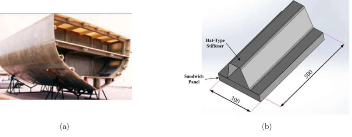
The 300 mm×500 mm rectangular sandwich composite panel specimens were prepared with identical materials and process conditions. The panels are stiffened with a laminated hat-shaped stiffener com-monly used in construction of composite ship hulls, according to Figure 1. Detailed geometry and dimensions of the specimens along with the location of the defect area are all illustrated in Figure 2.
(a) (b)
(a) (b)
Figure 2: (a): Geometry of the test specimen (viewed from the back) and location of the embedded defect; (b): Sectional view of the sandwich panel and attached stiffener (dimensions in mm).
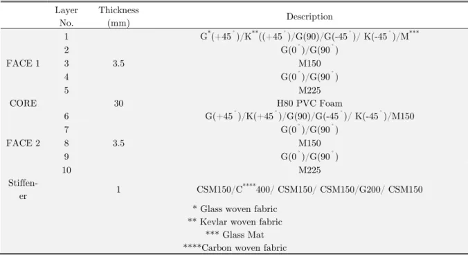
The specimens were manufactured using Vacuum Induced Process (VIP). The vinyl ester resin induced under the vacuum pressure, according to the lay-up design given in Table 1. In Table 2 the material properties of composite laminates are presented. For each specimen, a region with the di-mensions of 150 mm×250 mm , i.e. 25% of the total area, was devoted to the resin starved surface (Figure 2). Resin starvation usually occurs on one side of the specimens, where resin flow finds a shortcut towards the vacuum pipes. Thus, the artificial starvation defect is embedded only on one side of the specimens and the other face is perfectly constructed and stiffened.
Layer No.
Thickness
(mm) Description
FACE 1 1
3.5
G*(+45˚
)/K**((+45˚
)/G(90)/G(-45˚
)/ K(-45˚
)/M***
2 G(0˚
)/G(90˚
)
3 M150
4 G(0˚)/G(90˚)
5 M225
CORE 30 H80 PVC Foam
FACE 2 6
3.5
G(+45˚)/K(+45˚)/G(90)/G(-45˚)/ K(-45˚)/M150
7 G(0˚
)/G(90˚
)
8 M150
9 G(0˚
)/G(90˚
)
10 M225
Stiffen-er 1 CSM150/C
****400/ CSM150/ CSM150/G200/ CSM150
* Glass woven fabric ** Kevlar woven fabric
*** Glass Mat ****Carbon woven fabric
WR Ply (0-90)
Woven E-Glass (G)
Glass Mat(M)
WovenKevlar (K)
Ex(GPa) 15.34 8.7 31.23
Ey(GPa) 15.34 8.7 31.23
G (GPa) 5.14 3.42 5.23
߭ 0.30 0.28 0.36
Sx (MPa) 186 186 123
Sy (MPa) 186 186 123
Ss (MPa) 45 45 65
Table 2: Material properties of the composite laminates.
2.2 Preparing Specimens with Artificial Resin Starved Defect
As previously mentioned, in current research two practical approaches were proposed and investigated for inducing artificial resin starved defect in the sandwich structures. The load-carrying capacity in composite materials is highly dependent on the matrix-fiber bonding quality. Therefore, if the fibers are not filled with sufficient amount of resin in a certain region during the manufacturing process, a starved area without the load carrying capability would be produced. This region has no significant mechanical properties and could be neglected during simulation and analysis of the structure.
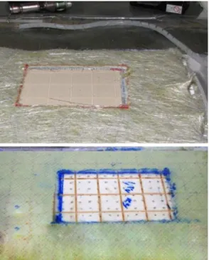
2.3 Elimination of the Fibers Before Resin Infusion Process (Plan 1)
In the first method, no laminate is applied in the region that is considered as the dry area. For this purpose, the fibers are removed from the structure with respect to dimensions of the dry area, and then the resin is infused into the structure (Figure 3).
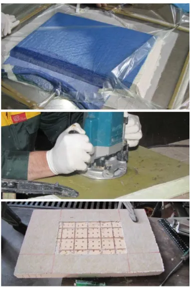
2.4 Elimination of the Fibers After Resin Infusion Process (Plan 2)
In plan 2, the specimen is produced completely with descent integrity after complete resin infusion, the panel is let to dry and finish the curing process. A rectangular area with certain dimensions is machined on the structure up to the desired depth with special instruments (Figure 4).
Figure 4: Steps of preparing the defected specimen according to the plan 2.
2.5 The Sample with a Natural Starved Area Defect Induced During the Manufacturing Process (Plan N)
Figure 5: Specimen with naturally-induced dry area defect during the manufacturing process.
2.6 Test Setup and Boundary Conditions
The samples prepared according to plans 1, 2 and N were subjected to uniform in-plane compres-sion, and their elastic behaviour prior to the fracture were compared to each other. The test rig consists of two vertical towers dimensioned to withstand the horizontal forces originating from the Poisson’s effect when the panel is compressed in the vertical direction. The forces are thus trans-ferred into the underlying bottom plate. The connection between the towers and the bottom plate is effected by four adjustment devices, where they are able to adjust the horizontal distance between the towers and make it possible to test the panels with varying breadths. Furthermore, four vertical and adjustable steel ribs ensure that the panel edges are not able to move in the out-of-plane direc-tion. Teflon tape is attached to the inside of the ribs, thus limiting friction between the panel and steel ribs. Finally, the loading is introduced by use of a horizontal steel beam attached to the test machine. The horizontal steel beam is specially shaped to be able to slide down between the steel ribs. The position of the beam can furthermore be adjusted in the out-of-plane direction. Such a test method covers compressive residual strength properties of multidirectional polymer matrix composite laminated plates. The test setup is shown in Figure 6. A special fixture was designed for performing the tests in order to satisfy the boundary conditions depicted in Figure 7.
Boundary's ID Number 1 2
3 4
Ux=0 Uy=Free
Uz=0
θx=0
θy=0
θz= Free Ux=0
Uy= Free Uz=0
θx=0
θy=0
θz= Free Ux=0
Uy=0 Uz=0
θx=0
θy=0
θz=0 Ux=0
Uy= Free Uz=0
θx=0
θy=0
θz= Free Boundary Conditions
Ux: Displacement along x-axis Uy: Displacement along y-axis Uz: Displacement along z-axis θx: Rotation about x-axis θy: Rotation about y-axis θz: Rotation about z-axis
Figure 7: Boundary conditions for the tested specimens (dimensions in mm).
3 EXPERIMENTAL MEASUREMENT AND TEST EQUIPMENT
In order to measure the average in-plane strain in vertical direction, unidirectional strain-gages were installed on the plane midline. TML UBF series unidirectional strain gages were applied on the specimen's intact surfaces. These Strain gages are specialized to measure the strain on the compo-site structures. The specimens were tested by installing the specialized fixture within a Shimadzu Autograph AG-25-TC universal testing machine with a loading capacity of 250 kN (Figure 8). The tests are performed in a displacement control mode, while the accuracy of the load cell is validated in conjunction with the tests so that it proves to be fairly accurate even for relatively limited forces below 10% of the maximum capacity. Values of the in-plane force exerted in vertical direction on each specimen and induced shortening are recorded as well as the average strain.
4 RESULTS AND DISCUSSIONS
Two specimens labeled as A and B were prepared for each of the plans. Based on the test results, the average in-plane strain in vertical direction (εy) is plotted in terms of the vertical shortening (εy), as shown in Figure 9. Considering the nature of loading and the magnitude of deformations, the cross–section of the specimen could be assumed constant so the average stress on the specimen could be calculated by dividing the measured force on the cross-sectional area. The relationship between the average in-plane stresses in vertical direction (εy) versus the average in-plane strain in vertical direction (εy) for all of the specimens are also plotted in Figure 10.
Figure 9: Relationship between the average in-plane strain in vertical direction (y)
Figure 10: Relationship between the average in-plane stress in vertical direction (y) and the average in-plane strain in vertical direction (y) for all specimens.
Experimentally measured values of the applied load on the top edge of the specimens, corre-sponding average in-plane stress in vertical direction in addition to the vertical shortening of speci-mens and also their compressive modulus in elastic range are all given in Table 3. Furthermore, fracture modes are shown in Figure 11 for all of the specimens.
Deflection of the Top Edge
dmax(mm)
Load Fmax (kN) Stress (MPa) Compressive Modu-lus Ec (MPa)
Specimen Code Defect Inducing Plan 13.0 114 10.270 353 ST1-A Plan 1 13.6 118 10.631 360 ST1-B 14.2 115 10.360 343 ST2-A Plan 2 13.8 115 10.327 361 ST2-B 14.1 120 10.811 368 N-1 Naturally-generated
Dry Area N-2 373 10.811 120 14.2
Table 3: Values of the load, stress and deflection of the top edge, and the compressive modulus at the ultimate point.
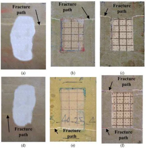
Figure 11: Comparison of the fracture modes for the tested specimens: (a) and (d): plan N; (b) and (e): plan 1; (c) and (f): plan 2.
Mechanical properties of the defected structures were also determined. As can be confirmed, properties such as the Young's modulus, maximum compressive stress and the ultimate load of the defected specimens are consistent with those of the naturally defected specimens. Hence, all the proposed plans for manufacturing artificially defected specimens could be practically employed for investigation of the mechanical properties of the defected structures. Delamination of the face sheet and core was the main considerable failure mode in the specimens. The failure mechanism and fail-ure load in all instances were similar. However, the behavior of the structfail-ures after failfail-ure was dif-ferent because of the foam shattering at the lading point, as well as many non-linear parameters involved in the fracture mechanics of the specimens.
5 CONCLUSIONS
materials, stacking sequence and production conditions. Behaviour of specimens with artificially embedded defects were compared with that of naturally defected specimens having the same size and material properties. Based on the experimental results, the proposed methods could be success-fully utilized in order to induce the artificial dry area defect in the structures. With such a capabil-ity, it would be possible to conduct more accurate experiments and further investigate the impact of dry area defect on the mechanical properties of the composite structures. Among all the suggested plans, the ST1 case was observed to have highest similarity to the natural instances. Also, if appli-cation of the methods is considered with the proposed plans, then resin starvation defects in certain number of layers could be well simulated. In other words, in the plan 1 method the number of lay-ers that should be located in the starved area can be eliminated in the stacking sequence and then the lay-up may be performed without those layers. Similar condition could be simulated in the plan 2 in which the laminate could be mechanically removed up to a certain depth with accurate ma-chining. Plan 2 would generate district separation lines on the designated resin starved zone which has multiple micro cracks that could be an appropriate zone of failure initiation. On the other hand, the defected area in the plan 1 is smoothly bonded to the rest of structure and there are no micro cracks present in that zone. An advantage of plan 1 over plan 2 is that more complex dry area ge-ometries can be generated while the plan 1 is practically limited to simple shapes. This difference must be taken into consideration before employing the proposed methods.
In this research two innovative approaches were introduced that could make it possible to em-bed controlled defects in composite sandwich specimens. These controlled defects may be used in further studies to characterize the effects of resin starvation defects on the strength of cored sand-wich composite structures.
References
Adams, Dan O. and Kuramoto, Brad. (2013) “Damage Tolerance Test Method Development for Sandwich Compo-sites,” University of Utah: Technical Review.
ASTM D7137 (2012) Standard Test Method for Compressive Residual Strength Properties of Damaged Polymer Matrix Composite Plates;
Barari, B., Ellingham, T.K., Ghamhia, I.I., Pillai, K.M. El-Hajjar, R., Turng, L-S., Sabo, R. (2016) Mechanical char-acterization of scalable cellulose nano-fiber based composites made using liquid composite molding process. Compo-sites Part B: Eng. 2016; 84:277-284.
De Mendibil, I.O., Aretxabaleta, L., Sarrionandia, M., Mateos, M., Aurrekoetxea, J. (2016) Impact behaviour of glass fibre-reinforced epoxy/aluminiumfibre metal laminate manufactured by Vacuum Assisted Resin Transfer Moulding. Compos Struct.;140:118-124.
Elliott, D.M. and Trask, R.S. (2001) “Damage tolerance and repair of GFRP Ships,” Jnl. of Thermoplastic Composite Materials, Vol. 14, No. 3, pp. 201-212.
Feldmann, M. (2016). The effects of the injection moulding temperature on the mechanical properties and morpholo-gy of polypropylene man-made cellulose fibre composites. Composites Part A: ApplSci Manuf. 2016; 87:146-152. Fotsing, E.R., Ross, A., Ruiz, Edu. (2014). Characterization of surface defects on composite sandwich materials based on deflectrometry, NDT&E International 62 29–39
Grujicic, M., Chittajallu, K., Walsh, S. (2005) Non-isothermal preform infiltration during the vacuum-assisted resin transfer molding (VARTM) process. Applied surface science. 245:51-64.
Gu, Y., Tan, X., Yang, Z., Zhang, Z. (2014) Hot compaction and mechanical properties of ramie fabric/epoxy com-posite fabricated using vacuum assisted resin infusion molding. Materials & Design. 56:852-861.
Pastuszak, Przemysław Daniel. (2016). Characterization of Defects in Curved Composite Structures Using Active Infrared Thermography, Procedia Engineering, Volume 157, Pages 325-332, ISSN 1877-7058.
Phil, E., Soutis, C. (2014). Polymer composites in the aerospace industry: Elsevier.
Ren, P-G., Hou, S-Y., Ren, F., Zhang, Z-P., Sun, Z-F., Xu, L. (2016). The influence of compression molding tech-niques on thermal conductivity of UHMWPE/BN and UHMWPE/(BN+ MWCNT) hybrid composites with segre-gated structure. Composites Part A: ApplSci Manuf; 90:13-21.
Sorrentino, Luca, Esposito, Luca, Bellini, Costanzo. (2017). A new methodology to evaluate the influence of curing overheating on the mechanical properties of thick FRP laminates, Composites Part B: Engineering, Volume 109, 15, Pages 187-196, ISSN 1359-8368,
Sumpter, J.D.G., Swift, A.C., Elliott, D.M., Faulke, D., Court, R. and Lay, P.W. (1997). “Damage Tolerance of GRP Ships,” Proc. Int. Conf. on Advances in Marine Structures III, Dunfermline, Scotland.
Teixeira, D., Giovanela, M., Gonella, L., Crespo, J. (2015) Influence of injection molding on the flexural strength and surface quality of long glass fiber-reinforced polyamide 6.6 composites. Materials & Design; 85:695-706.
Wang, J., Chen, D. (2016) Microcellular polypropylene single-polymer composites prepared by insert-microcellular injection molding. Composites Part A: Appl Sci Manuf. 90:567-576.