Abs tract
Derived from flexibility matrix, Uniform Load Surface (ULS) is used to identify damages in beam-type structures. This method is beneficial in terms of more participating the lower order modes and having less prone to noise and irregularities in the measured data in comparison with the original flexibility matrix technique. Therefore, these characteristics make this approach a practical tool in the field of damage identification. This paper presents a procedure to employ stationary wavelet transform multi-resolution analysis (SWT-MRA) to refine ULS obtained from the damaged structure and then using continuous wavelet transform (CWT) for localizing the discontinuity of improved ULS as a sign of damage site. Evaluation of the proposed method is carried out by examin-ing a cantilever beam as a numerical case, where the ULS is formed by using mode shapes of damaged beam and two kinds of wavelets (i.e. symmetrical 4 and bior 6.8) is applied for discerning the induced crack. Moreover, a laboratory test is conducted on a free-free beam to experimentally evaluate the practicability of the technique.
Key words
Modal analysis, damage detection, wavelet analysis, flexibility matrix, uniform load surface
Damage Identification from Uniform Load Surface U
s-ing Continuous and Stationary Wavelet Transforms
1 BACKGROUND
The wide assortment of efforts has been dedicated to assess the influence of damages on dynamic behavior of structures with the aim of proposing new techniques to localize flaws and cracks (Far-rar and Worden, 2007; Alvandi and Cremona, 2006; Yan et al, 2007; Morassi and Vestroni, 2008; Farrar et al, 2001). Two fundamental dynamic properties including natural frequencies and mode shapes have gained more attention in the field of damage identification through modal analysis. Based on different numerical methods and state of the art signal processing techniques, different
M. M as oum i , M. R. A s ho ry*
Modal Analysis Laboratory, School of Me-chanical Engineering, Semnan University, P. O. Box 35195-363, Semnan, Iran
Received in 21 Sep 2012 In revised form 02 Aug 2013
*Author email:
Latin American Journal of Solids and Structures 11 (2014) 738-754 procedures have been introduced. Up to now, fractal dimension (FD) and generalized fractal di-mension (GFD) technique, gapped smoothing method (GSM), strain energy method (SEM), dif-ferential quadrature method (DQM), global fitting method (GFM), and applying the discrete and continuous wavelet transforms to the mode shapes (Ratcliffe , 1997; Liew and Wang, 1998; Hong et al, 2002; Hadjileontiadis et al, 2005; Hadjileontiadis and E. Douka, 2007; Wang and Qiao, 2007; Qiao et al, 2007; Yoon et al, 2005, 2010), flexibility matrix or uniform load surface (ULS) (Qiao et al, 2007; Bakhshizade et al, 2011; Masoumi and Ashory, 2012) have been used.
A fractal dimension-based crack detector (FDCD) was put forward by Hadjileontiadis et al (Hadjileontiadis et al, 2005; Hadjileontiadis and E. Douka, 2007). They proved that since fractal dimension is able to measure the complexity of a signal, it can be used as a damage detector due to the fact that any crack in structure results in more complex vibrational signal. So as to im-prove some shortcoming of the FD method in specific situations, Wang and Qiao (Wang and Qi-ao, 2007) recommended GFD and modified FD by adding a scale parameter. SEM was firstly proposed by Stubbs et al (Stubbs et al, 1992) where their formulations were rooted in the strain energy of a Bernoulli-Euler beam and needed to have access to both mode shapes of intact and damaged structure. This technique was also used for plate-type structures by Cornwell et al (Cornwell et al, 1999). Bakhshizade et al (Bakhshizade et al, 2011) originally used DQM to eval-uate a damaged beam and successfully localized the crack. GSM was brought into play by Ratcliffe (Ratcliffe, 1997) where he used a modified Laplacian operator to identify small damages from the fundamental mode shape of the damaged structure. GFM, which is an extended tech-nique based on GSM, was developed by Yoon et al (Yoon et al, 2005, 2010) to detect damage in both beam- and plate-type structures.
Granted Liew and Wang (Liew and Wang, 1998) firstly used spatial discrete wavelet trans-form (DWT) to examine a numerical model of a simply supported damaged beam, but their method was in need of an oscillating excitation along the length of the beam. Wang and Deng (Wang and Deng, 1999) carried out an investigation on the use of DWT in vibration based dam-age detection. Their technique was based on applying Haar DWT to the measured displacement, strain or acceleration. Hong et al (Hong et al, 2002) studied the use of Mexican hat continuous wavelet transform (CWT) with the aim of finding damage in a numerically modeled beam. Cao and Qiao (Cao and Qiao, 2008) proposed a method to have synergistic advantages of stationary wavelet transform (SWT) and CWT simultaneously. Their method includes implementing SWT Multiresolution analysis (SWT-MRA) to refine the obtained mode shapes of a damaged beam and then looking for damage site through applying CWT to the refined mode shapes.
Latin American Journal of Solids and Structures 11 (2014) 738-754
In this paper, a new approach is used based on three major steps. First, extracted mode shapes of damaged beam are employed to form ULS and then SWT-MRA is used to improve the ob-tained ULS and eliminate the irregularities and noises. Finally, the location of the induced crack is detected by using CWT multiscale analysis.
2 FUNDAMENTAL THEORIES
2.1Wavelet Theories
CWT of a space domain signal is given by
CW
(
τ
,s)
=
f
(x)
ψ
*τ,s
(x)
dx
=
−∞ ∞
∫
ψ
τ,s(x),
f
(
x)
(1)where
ψ
*(
x
)
is the complex conjugate of the mother wavelet. The mother wavelet is defined asψ
τ,s(
x
)
=
1
a
ψ
x
−
s
τ
⎛
⎝⎜
⎞
⎠⎟
(2)in which,
τ
,
s
are translation and scale parameters respectively (τ
,
s
∈ℜ
,
τ
>
0
). When the des-ignated scale is large, global view of the signal is provided and when small-scale is selected, a detailed view of the signal is given. Any function can be chosen as the mother wavelet if it satis-fies the following admissibility conditionΨ
(
ω
)
2ω
d
ω
<
∞
−∞ ∞
∫
(3)Here,
Ψ
(
ω
)
is the Fourier transform ofψ
(
x
)
. Choosing the different mother waveletspro-vides various wavelet transforms. In this work, symmetrical 4 and bior 6.8 are selected as wavelet functions to identify damages in a beam structure.
Although CWT has been extensively used in the field of damage detection, it has some inca-pability in the face of noisy data. To overcome this weakness, SWT is used to de-noise the ob-tained data before applying CWT to find damage location. SWT is similar to DWT except that the number of wavelet coefficients at each level remains equal to the number of sampling points of the original signal while using DWT results in reduction of the number of coefficients by
N
2
L, where N is the number of sampling points of the original signal and L stands for Lth
Latin American Journal of Solids and Structures 11 (2014) 738-754 basis functions. By setting
τ
=
ξ
0j,
s
=
k
ξ
0jζ
0 in which
ξ
0>
1
is a dilated step andζ
0≠
0
is atranslation step, the family of wavelets is given by
ψ
j,k(x)
=
ξ
0−j
2
ψ
(
ξ
0−j
x
−
k
ζ
0)
(4)and DWT of a given signal f(x) is defined as
DW
(
j
,
k
)
=
ψ
*j,k(
x
)
f
(
x
)
=
ψ
j,k(
x
),
f
(
x
)
−∞∞
∫
(5)As Cao and Qiao mentioned (Cao and Qiao, 2008), DWT has a significant drawback in com-parison to SWT. Although DWT can decompose a multicomponent signal into a group of compo-nent signals and remove unnecessary compocompo-nents, shift variance characteristic causes inaccurate outcomes in damage location procedure. This problem is especially noticeable when the sampling points are not close to each other and the measured data is not a high-resolution signal. It is worth mentioning that in this work, spline interpolation is utilized to increase the number of data points and provide smooth data, which is used as an input signal for wavelet analysis.
2.2 ULS Theory
Modal flexibility matrix for a system with m measured modes is approximately given by
F
m
≈
φ
rφ
r Tω
r 2 r=1m
∑
(6)By defining the deflection vector under uniform load for a system with n degrees of freedom
η
j,k=
f
1,1f
1,2f
2,1f
2,2
f
1,n
f
2,n
f
n,1f
n,2
f
n,n⎡
⎣
⎢
⎢
⎢
⎢
⎢
⎢
⎢
⎤
⎦
⎥
⎥
⎥
⎥
⎥
⎥
⎥
1
1
1
⎧
⎨
⎪⎪
⎩
⎪
⎪
⎫
⎬
⎪⎪
⎭
⎪
⎪
(7)ULS is obtained as:
u j
( )
=
k=1n
∑
η
j,k=
k=1n
∑
r=1
m
∑
φ
rj
φ
r kω
r 2⎛
⎝
⎜
⎞
⎠
⎟
=
r=1
m
∑
φ
rj k=1
n
∑
φ
rk
ω
rLatin American Journal of Solids and Structures 11 (2014) 738-754
where
φ
r is the rth mode shape of damaged structure andω
r stands for the r
th natural
frequen-cy.
f
i,j is the modal flexibility at the point i under the unit load at the point j. As Zhang andAktan (Zhang and Aktan, 1998) maintained, the inverse of the square of the frequency leads to the less contribution of higher order modes in comparison to the flexibility matrix and truncation error, stemmed from using lower order modes, can be small for a system with well-separated fre-quencies. In the flexibility matrix based damage detection techniques, if either deflection location and load location or one of them is placed at the boundaries, an error may cause due to the high noise to signal ratio. They observed that ULS is less error-sensitive than the original modal flexi-bility.
3DISCUSSION ABOUT THE CHOICE OF WAVELET
Over the almost twenty years of using wavelet transform for damage identification many different wavelet transforms have been used and their efficiency has been evaluated for numerical and ex-perimental cases. Ovanesova and Suarez (Ovanesova and Suarez, 2004) showed that Morlet, Mex-ican Hat, Gaussian and Shannon wavelets are not suitable to use as DWT due to the lack of the scaling function. In addition, different authors have used various wavelets such as Symlets (Kha-tam et al, 2007), Coiflets (Carrión et al 2006; Rucka and Wilde, 2006), biorthogonal (Cao and Qiao, 2008; Ovanesova and Suarez, 2004; Prasad et al 2006; Masoumi and Ashory, 2012),
Daubechies (Hou et al, 2000) and symmetrical (Douka et al, 2003). Although a high number of vanishing moments leads to better outcomes, increasing the vanishing moments needs to provide longer support because a wavelet holding n vanishing moments should have at least 2n-1 support length (Hong et al, 2002). In this paper two mother wavelets called symmetrical 4 and biorthogo-nal, mentioned by previous authors as efficient and practical in damage detection of beam type structures (Cao and Qiao, 2008; Ovanesova and Suarez, 2004; Prasad et al 2006; Masoumi and Ashory, 2012; Douka et al, 2003), are used.
4 NUMERICAL CASE STUDY
A cantilever beam, as a numerical case, is considered so as to investigate the proposed method. Its properties are as follows: width of 0.045 m, height of 0.012 m, length of 1 m, Young’s Modulus
of 200 Gpa, and density of
ρ
=
7850
kg
m
3. The number of elements of FE model is fifty andLatin American Journal of Solids and Structures 11 (2014) 738-754 Figure 1 Layout of the damaged beam
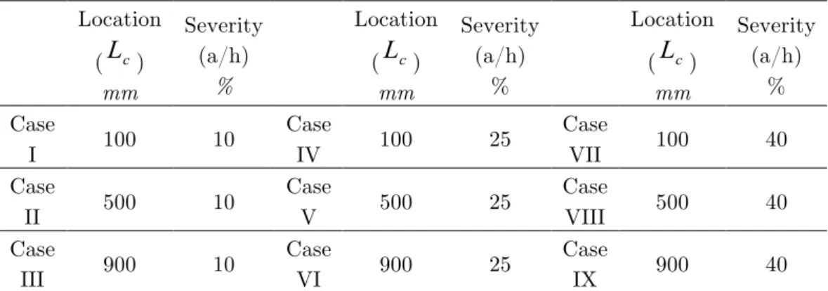
Table 1 Damage Scenarios
Location
(
L
c)mm
Severity (a/h)
%
Location
(
L
c)mm
Severity (a/h)
%
Location
(
L
c)mm
Severity (a/h)
% Case
I 100 10
Case
IV 100 25
Case
VII 100 40
Case
II 500 10
Case
V 500 25
Case
VIII 500 40
Case
III 900 10
Case
VI 900 25
Case
IX 900 40
Table 2 shows the first six natural frequencies before and after inducing damage on the beam. As expected, an increase in damage severity results in decreasing the natural frequencies. For cases close to the free-end, first natural frequency is unchanged while higher order natural fre-quencies provide more tangible variations. One can conclude that the prediction of damage size based on only variation of frequencies of damaged beam and having no information from its FE model is not feasible owing to the fact that a decrease in frequencies ensuing from damage is con-tingent on damage site.
Table 2 Comparison of natural frequencies for nine damage scenarios
Natural
Frequency (Hz) Intact beam
Case I
Case
II Case III Case IV
Case
V Case VI Case VII Case VIII Case IX
First 9.78 9.75 9.78 9.78 9.50 9.73 9.78 9.32 9.70 9.78
Second 61.32 61.25 61.16 61.31 60.78 60.08 61.29 60.44 59.28 61.27
Third 171.69 171.67 171.69 171.63 171.52 171.68 171.18 171.41 171.67 170.81
Fourth 336.45 336.41 335.59 336.11 336.16 330.00 333.69 335.96 326.00 331.72
Fifth 556.18 555.75 556.14 555.14 552.86 555.89 547.89 550.73 555.70 542.14
Latin American Journal of Solids and Structures 11 (2014) 738-754
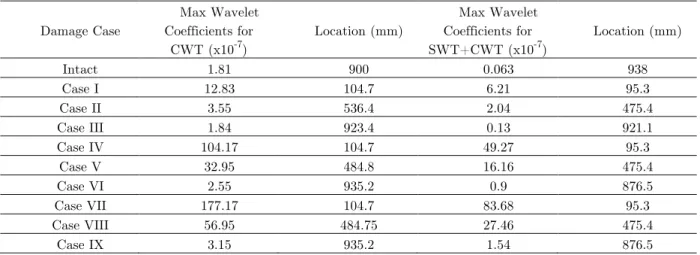
ULSs were formed using eq. (8) for each case. Not only maximum wavelet coefficients of sym-metrical 4 CWT and bior6.8 CWT but also all of the coefficients, before and after refining the ULSs by utilizing SWT, were obtained and tabulated in Table 3, Table 4 and graphically depict-ed in Figures 3-11.
As presented in Table 3 and Table 4, although there is no damage in the intact state of the beam, the maximum wavelet coefficient is almost equal to the coefficient obtained for case III where 10 percent damage was induced at 100 mm from free-end of the beam. This problem stems from irregularities in wavelet coefficients at the free-end boundary and it has been undermined by refining the data by using SWT before implementing symmetrical 4 CWT. Generally, wavelet coefficients are decreased due to the use of SWT to refine the vibration data, but this issue is worth dealing because of the compensation received from this technique where a noticeable re-duced amount of unfavorable abnormalities is seen in the results.
Table 3 Maximum wavelet coefficients for symmetrical 4 and the corresponding locations
Damage Case
Max Wavelet Coefficients for
CWT (x10-7)
Location (mm)
Max Wavelet Coefficients for SWT+CWT (x10-7)
Location (mm)
Intact 1.81 900 0.063 938
Case I 12.83 104.7 6.21 95.3
Case II 3.55 536.4 2.04 475.4
Case III 1.84 923.4 0.13 921.1
Case IV 104.17 104.7 49.27 95.3
Case V 32.95 484.8 16.16 475.4
Case VI 2.55 935.2 0.9 876.5
Case VII 177.17 104.7 83.68 95.3
Case VIII 56.95 484.75 27.46 475.4
Case IX 3.15 935.2 1.54 876.5
Table 4 Maximum wavelet coefficients for bior6.8 and the corresponding location
Damage Case
Max Wavelet Coefficients for
CWT (x10-7)
Location (mm)
Max Wavelet Coefficients for SWT+CWT (x10-7)
Location (mm)
Intact 0.96 945 0.048 937.5
Case I 10.91 109.3 6.22 100
Case II 3.55 489.4 2.04 480
Case III 1.03 937.5 0.12 878.9
Case IV 86.38 109.4 49.36 100
Case V 28.2 489.4 16.2 480
Case VI 1.66 940 0.92 878.9
Case VII 146.7 109.4 83.84 100
Case VIII 47.93 489.4 27.52 480
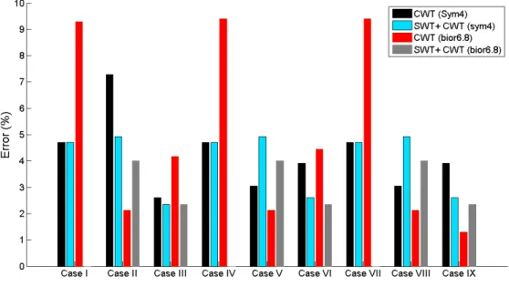
Latin American Journal of Solids and Structures 11 (2014) 738-754 Inaccuracy in damage localization by utilizing CWT and SWT+CWT techniques for both wavelet transforms have been provided in Figure 2, where the error of each approach is presented. When the induced damage is at the location close to the clamped-end, the use of bior6.8 CWT provides us with the maximum value of error in the results whereas the use of SWT in association with bior6.8 CWT leads to a completely accurate localization procedure, containing no error. At these locations, i.e. close to the clamped-end, error in localization for symmetrical 4 CWT is equal to the error obtained through employing SWT in conjunction with symmetrical 4 CWT. When the crack is in the middle of the beam, bior6.8 CWT has the minimum error and an increase in damage severity results in a decrease in estimated error of damage localization for symmetrical 4
CWT approach while the error in other three approaches remains consistent.
Latin American Journal of Solids and Structures 11 (2014) 738-754
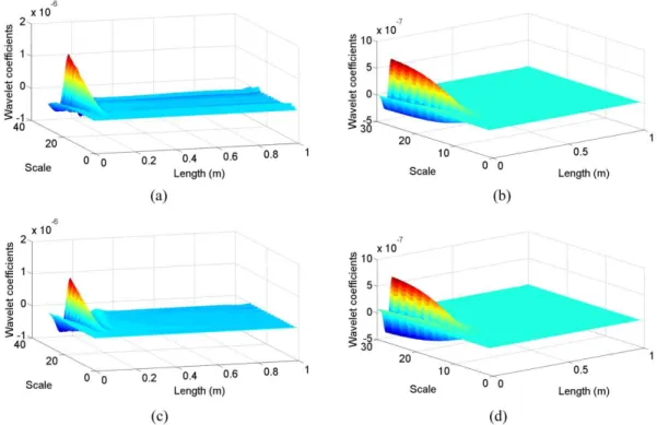
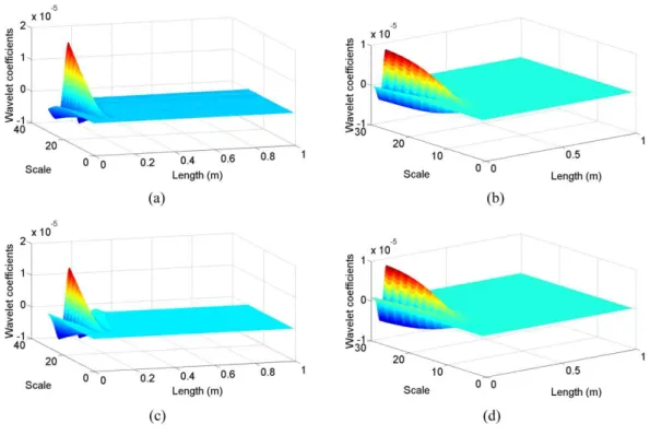
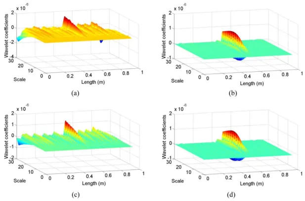
Figure 3 Wavelet coefficients for Case I: (a) symmetrical 4 CWT, (b) SWT+ symmetrical 4 CWT, (c) bior6.8 CWT, (d) SWT+ bior6.8 CWT
Latin American Journal of Solids and Structures 11 (2014) 738-754 Figure 5 Wavelet coefficients for Case III: (a) symmetrical 4 CWT, (b) SWT+ symmetrical 4 CWT, (c) bior6.8 CWT, (d) SWT+
bior6.8 CWT
Latin American Journal of Solids and Structures 11 (2014) 738-754
Figure 7 Wavelet coefficients for Case V: (a) symmetrical 4 CWT, (b) SWT+ symmetrical 4 CWT, (c) bior6.8 CWT, (d) SWT+ bior6.8 CWT
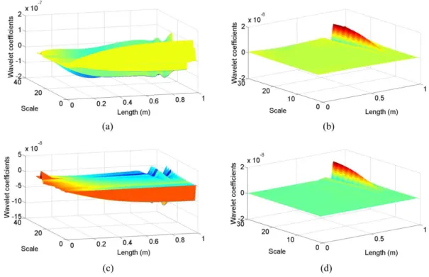
Latin American Journal of Solids and Structures 11 (2014) 738-754 Figure 9 Wavelet coefficients for Case VII: (a) symmetrical 4 CWT, (b) SWT+ symmetrical 4 CWT, (c) bior6.8 CWT, (d) SWT+
bior6.8 CWT
Latin American Journal of Solids and Structures 11 (2014) 738-754
Figure 11 Wavelet coefficients for Case IX: (a) symmetrical 4 CWT, (b) SWT+ symmetrical 4 CWT, (c) bior6.8 CWT, (d) SWT+ bior6.8 CWT
Figures 3-11 show the wavelet coefficients for all damage scenarios, which are described in Ta-ble 1. In all cases, using SWT to refine the data before applying CWTs has almost eliminated the unfavorable irregularities in the results. These figures indicate that locating damage close to the free-end causes more irregularities even though this effect decreases with increasing the damage severity. Moreover, they confirm the results provided in Table 3 and 4 showing that an increase in damage size brings about an increase in wavelet coefficients at the crack site and also coeffi-cients are larger for symmetrical 4 CWT compared to bior6.8 CWT. The privilege of using the SWT_MRA is more noticeable when the crack is located close to the free-end where before refin-ing the data by usrefin-ing SWT, it is challengrefin-ing to discern the location of crack especially for sym-metrical 4 CWT.
5 EXPERIMENTAL CASE STUDY
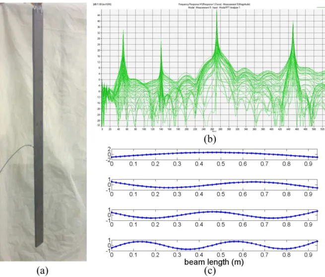
Latin American Journal of Solids and Structures 11 (2014) 738-754 obtained first four mode shapes are shown in Figure 12. As shown, no sign of damage is noticed in the obtained mode shapes without using signal processing techniques.
Figure 12 (a) hammer test setup configuration (b) 46 measured FRFs (c) First four mode shapes of free-free damaged beam
Eq. (8) was used to form ULS and then spline interpolation and extrapolation were utilized to smooth the interior and boundary points of the formed ULS. At the first step, symmetrical 4 and
bior 6.8 were employed to find the damage site. Results are shown in Figure 13 (a) and (c). Even though the damage site is detectable, there are irregularities especially at the boundaries. In order to de-noise the results and achieve outcomes with less irregularity, SWT_MRA was firstly used to refine the ULS of damaged beam and then wavelet coefficients of symmetrical 4 and bior6.8
Latin American Journal of Solids and Structures 11 (2014) 738-754
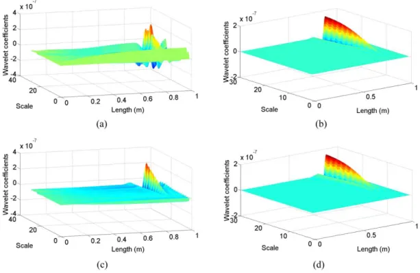
Figure 13 Wavelet coefficients for experimental case: (a) symmetrical 4 CWT, (b) SWT+ symmetrical 4 CWT, (c) bior6.8 CWT, (d) SWT+ bior6.8 CWT
It can be seen that the wavelet coefficients at damage location are decreased compared to us-ing CWT but most of the abnormalities in the coefficients are eliminated. The only point that should be noticed in the experimental case is that increasing the scale parameter for this ap-proach is not a route to provide better results and as it shown in this case, there is a specific suit-able range of scales for aptly finding the crack.
6SUMMARY AND CONCLUSIONS
Latin American Journal of Solids and Structures 11 (2014) 738-754 A cknow ledgem ents This work is supported by the Talented Office of Semnan University.
References
Alvandi A. and Cremona C. Assessment of vibration-based damage identification techniques. Journal of Sound and Vibration, 292(1-2): 179–202, 2006.
Bakhshizade A., Ashory M. R., Masoumi M. and Salmani A. non model-based damage detection method us-ing generalized flexibility matrix. International Operational Modal Analysis Conference, Istanbul, Turkey, 2011.
Cao M. and Qiao P. Integrated wavelet transform and its application to vibration mode shapes for the dam-age detection of beam-type structures. Smart Mater. Struct., 17(5): 1–17, 2008.
Carrión F., Lozano A. and Castaño V. Condition monitoring of vibrating steel-reinforced concrete beams through wavelet transforms. Structural Survey, 24(2): 154-162, 2006.
Cornwell P., Doebling S. W., and Farrar C. R. Application of the strain energy damage detection method to plate-like structures. Journal of Sound and Vibration, 224(2): 359-374, 1999.
Douka E., Loutridis S. and Trochidis A. Crack identification in beams using wavelet analysis. International Journal of Solids and Structures, 40(13-14): 3557–3569, 2003.
Farrar C. R. and Worden K. An introduction to structural health monitoring. Phil. Trans. R. Soc., 365(1851):303-315, 2007.
Farrar C. R., Doebling S. W., and Nix D. A. Vibration–based structural damage identification. Phil. Trans. R. Soc., 359(1778): 131-149, 2001.
Hadjileontiadis L. J. and Douka E. Crack detection in plates using fractal dimension, Engineering Structures, 29(7): 1612–1625, 2007.
Hadjileontiadis L. J., Douka E., and Trochidis A. Fractal dimension analysis for crack identification in beam structures. Mechanical Systems and Signal Processing, 19(3): 659–674, 2005.
Hong J. C., Kim Y. Y., Lee H. C., and Lee Y. W. Damage detection using the Lipschitz exponent estimated by the wavelet transform: applications to vibration modes of a beam. International Journal of Solids and Structures, 39(7): 1803–1816, 2002.
Hou Z., Noori M. and Amand R.S. Wavelet-based approach for structural damage detection. Journal of En-gineering Mechanics, 126(7): 677-683, 2000.
Khatam H., Golafshani A.A., Beheshti-Aval S. and Noori M. Harmonic class loading for damage identifica-tion in beams using wavelet analysis. Structural Health Monitoring, 6(1): 67-80, 2007.
Liew K. M. and Wang Q. Application of wavelet theory for crack identification in structures. Journal of En-gineering Mechanics, 124(2): 152-158, 1998.
Masoumi M. and Ashory M. R. Damage localization by wavelet analysis of uniform load surface. Journal of Vibroengineering, 14(1): 395-407, 2012.
Morassi A. and Vestroni F. Dynamics Methods for Damage Detection in Structures. SpringerWienNewYork, 2008.
Ovanesova A. and Suarez L. Applications of wavelet transforms to damage detection in frame structures. En-gineering Structures, 26(1): 39-49, 2004.
Latin American Journal of Solids and Structures 11 (2014) 738-754
and Vibration, 169(1): 3-17, 1994.
Prasad B.K.R., Lakshmanan N., Muthumani K. and Gopalakrishnan N. Enhancement of damage indicators in wavelet and curvature analysis. Sadhana, 31(4): 463-486, 2006.
Qiao P., Lu K., Lestari W., and Wang J. Curvature mode shape-based damage detection in composite lami-nated plates. Composite Structures, 80(3): 409–428, 2007.
Ratcliffe C. P. Damage detection using a modified Laplacian operator on mode shape data. Journal of Sound and Vibration, 204(3): 505-517, 1997.
Rucka M. and Wilde K. Crack identification using wavelets on experimental static deflection profiles. Engi-neering Structures, 28(2): 279-288, 2006.
Stubbs N., Kim J. T., and Topole K. An efficient and robust algorithm for damage localization in offshore platforms. In Proceedings of the ASCE Tenth Structures Congress, pages 543-546, 1992.
Wang J. and Qiao P. Improved Damage Detection for Beam-type structures using a Uniform Load Surface. Structural Health Monitoring, 6(2): 99-110, 2007.
Wang Q. and Deng X. Damage detection with spatial wavelets. International Journal of Solids and Struc-tures, 36(23): 3443–3468, 1999.
Wu D. and Law S. S. Damage localization in plate structures from uniform load surface curvature. Journal of Sound and Vibration, 276(1-2): 227-244, 2004.
Yan Y. J., Cheng L., Wu Z. Y., and Yam L. H. Development in vibration-based structural damage detection technique. Mechanical Systems and Signal Processing, 21(5): 2198–2211, 2007.
Yoon M. K., Heider D., Gillespie J. W., Ratcliffe C. P., and Crane R. M. Local damage detection using the two-dimensional gapped smoothing method. Journal of Sound and Vibration, 279(1-2): 119-139, 2005.
Yoon M. K., Heider D., Gillespie J. W., Ratcliffe C. P., and Crane R. M. Local damage detection with the global fitting method using operating deflection shape data. J Nondestruct Eval., 29(1): 25-37, 2010.