FINITE SATISFIABILITY VERIFICATION IN UML
CLASS DIAGRAMS – A COMPARATIVE STUDY
Paulo Bastos
. ISCTE-IUL – University Institute of Lisbon. Avenida das Forças Armadas, Lisbon, Portugal.Pedro Ramos
. ISCTE-IUL – University Institute of Lisbon. Avenida das Forças Armadas, Lisbon, Portugal.ABSTRACT
Unified Modeling Language class diagrams are widely used for modeling, playing a key role in the analysis and design of information systems, especially in development contexts that use modeling oriented methodologies. Therefore, it is relevant to ensure the creation and maintenance of correct class diagrams. With the use of class diagrams it is possible to specify classes, relations and restrictions, however, such diagrams are subject to modeling errors made by their authors and may degenerate into incorrect diagrams. A common cause of incorrect diagrams refers to the definition of contradictory and inconsistent constraints, leading to finite satisfiability problems. Several approaches to the verification of finite satisfiability are currently available, supported by different tools. Through this work, we proceed with the identification and comparison of the existing approaches for the verification of finite satisfiability in class diagrams, determining the effectiveness and efficiency of the proposed tools.
KEYWORDS
Finite satisfiability, class diagrams, Unified Modeling Language.
1. INTRODUCTION
During recent years, Unified Modeling Language (UML) has emerged as a widely used standard in the analysis and design of information systems. UML is used to specify, visualize, construct and document the artifacts of an information system, providing itself as an essential analysis and modeling tool for system architects, engineers and software analysts (Rumbaugh et al. 1999). Additionally, UML can also be used for modeling business process, modeling databases and also modeling software unrelated aspects. UML provides a set of diagrams that allow the representation of several aspects of an information system. However, the class diagram is the most used diagram, with an adoption rate of 73% in projects that use UML for modeling purposes (Dobing and Parsons 2006).
Considering the key role of modeling in the analysis and design of information systems, especially in modeling focused contexts, such as Model-Driven Development (Mellor et al. 2003) and Model-Driven Architecture (Mellor et al. 2002), it becomes relevant to ensure the creation and maintenance of correct UML diagrams.
By using UML class diagrams, we can specify classes, their associations and constraints. However, these diagrams are subject to modeling errors by their authors and can degenerate into incorrect diagrams. Even with the use of Computer-Aided Software Engineering (CASE) tools to assist the process of modeling data, such does not prevent the creation of incorrect models, since CASE tools allow the creation of incorrect class diagrams.
The creation of incorrect class diagrams causes several problems, which are related to different characteristics of UML models quality, such as coherence, correctness, completeness and consistency (Unhelkar 2005). The existence of problems in a class diagrams has an impact on the software development life cycle (SDLC), particularly when it relies on model dependent code generation methods.
This study focuses on a recognized problem in UML class diagrams: finite satisfiability (Berardi et al. 2005). We are in presence of finite satisfiability problems when it is impossible to instantiate a class diagram. More formally, when its instantiation requires the existence of empty or infinite classes in order to satisfy the constraints present in the diagram (Balaban et al. 2010).
Finite satisfiability problems occur due to inadequate designs, e.g., conflicting constraints. In the presence of complex diagrams, conflicting constraints are sometimes near impossible to detect by humans. In data warehouse projects, when it is necessary to import data from multiple sources, conflicting constraints are also common.
The verification of finite satisfiability in class diagrams can be performed manually, however, due to the visual nature of the class diagram, it is a time consuming and error-prone operation. Additionally, current commercial CASE tools do not provide functionalities for the verification of finite satisfiability in UML class diagrams (Cadoli et al. 2007; Balaban et al. 2010).
Through this study, we proceeded with the identification and comparison of approaches to finite satisfiability verification in UML class diagrams, with the objective of comparing the characteristics, advantages and disadvantages of the approaches, their effectiveness and efficiency, as well as determining which approaches and respective tools are most appropriated for finite satisfiability verification. By doing so, we offer a unique contribution to the existing literature in the field of finite satisfiability verification, which is scarce in comparative studies and practical usage scenarios. Additionally, the findings of this study provide a support guide for users when choosing a tool for finite satisfiability verification in UML class diagrams.
The paper is organized as follows: in section 2 we present and motivate the problem of finite satisfiability in class diagrams. In section 3, different approaches to finite satisfiability automatic verification are briefly presented. In section 4 we compare those approaches using a comparison framework defined by the authors. Some concluding remarks are presented in the last section.
2. FINITE SATISFIABILITY IN CLASS DIAGRAMS
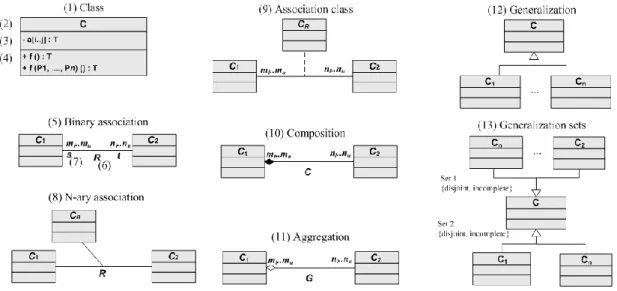
A class diagram is a model abstraction of a real word scenario and it presents a visual representation of the structure of an information system. The main components of a class diagram are classes and associations (see Fig. 1).
Figure 1. Basic components of a UML class diagram
A class (1) describes a set of objects that share the same specifications, constraints and semantics, and it is defined by its name (2), attributes (3) and operations (4). From a class an object can be created, through a process named instantiation.
An association represents a relation between classes and it is defined by its role in the association (6) and its multiplicity (7). Multiplicity acts as a restriction, by defining the participation level of a class instance with the other class, i.e., the number of minimum and maximum objects allowed. Additional basic components of a class diagram are: binary association (5), n-ary association (8), association class (9), composition (10), aggregation (11), generalization (12) and generalization set (13).
A detailed explanation of the class diagrams components and semantics can be found in the existing literature (Rumbaugh et al. 1999; Booch et al. 2005).
Finite satisfiability is one of the inherent characteristics in class diagrams correctness, which is an aspect of UML class diagrams quality. A finite satisfiability problem is a symptom of an error that occurred in the analysis phase of software development (Cadoli et al. 2007), usually caused due to conflicting constraints specifications that impose multiplicity requirements that can only be satisfied by empty or infinite classes. Naturally, a diagram that can only be instantiated using empty or infinite classes does not have any practical use.
A class is considered finitely satisfiable if it has a non-empty extension in a legal finite instance. A class diagram is considered finitely satisfiable if all classes are finitely satisfiable (Balaban et al. 2010). A legal instance refers to an instance of a class diagram where all classes and associations meet the restrictions of the diagram, i.e., there is no violation of the restrictions.
The term used for finite satisfiability can vary between authors. Some authors refer to the concept of finite satisfiability in two different levels: strong satisfiability and weak
satisfiability (Berardi et al. 2005; Cabot et al. 2008). The term strong satisfiability is
equivalent to the term finite satisfiability for the classification of a diagram, both having the same meaning. The term weak satisfiability is used to classify a class diagram that has at least one class that is finitely satisfiable (Cabot et al. 2008). The authors adopted the term finite
satisifiability for this work.
The verification of finite satisfiability is relevant in the context of software applications and databases, since the number of instances is intrinsically finite. In large real world class diagrams, finite satisfiability problems can easily arise due to the dimension of the diagrams and the edition of different parts of a diagram by different analysts. These problems are unlikely to be discovered manually (Cadoli et al. 2007).
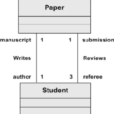
In order to illustrate a diagram with a finite satisfiability problem, consider the example in Fig. 2.
Figure 2. Example of a UML class diagram with a finite satisfiability problem. Source: Figure adaption from Cabot et al. (2008).
The model illustrated in Fig. 2 is considered finitely unsatisfiable. The multiplicity of the association Reviews mandates that exactly three student review a paper, however, the multiplicity of the Writes association, simultaneous mandates exactly one student as an author of a paper. One might imagine the instantiation of this model and verify that the instantiation of an object of the class Paper would generate three objects of the class Student, which by them self would generate newer Paper objects and subsequently new Student objects, in an infinite process. Since only an infinite or empty instantiation may satisfy both constraints simultaneously, it is said that this diagram presents a finite satisfiability problem and it is finitely unsatisfiable.
The fact that the presented diagram has a problem of finite satisfiability, does not presuppose the absence of a possible diagram that would satisfy the desired restrictions. However, the creation and maintenance of diagrams is an error prone operation and there is a recognized tendency for the occurrence of undetected errors in large scale UML models (Lange and Chaudron 2006).
Additional examples of finite satisfiability problems can be found in the existing literature (Balaban et al. 2010; Cabot et al. 2008; Cadoli et al. 2007).
3. APPROACHES TO FINITE SATISFIABILITY
VERIFICATION
Considering the importance of class diagrams and the need to produce models with quality, it becomes relevant the existence of additional functionalities to CASE tools, in order to provide methods for reasoning in UML diagrams and identify potential problems (Berardi et al. 2005; Cadoli et al. 2007; Balaban et al. 2010).
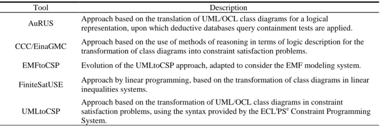
Several studies have been performed in order to obtain answers to the problem of finite satisfiability in UML class diagrams. Currently, there are several approaches to the subject, which involve the use of different tools. The set of approaches referred in this comparative study are identified by their respective tools in Table 1.
Current solutions for the verification of finite satisfiability employ different formalisms, such as linear programming (Maraee and Balaban 2007), deductive databases query containment tests (Queralt and Teniente 2006) and constraints satisfaction problems (Cabot et al. 2008; Cadoli et al. 2007). All approaches take in consideration the use of UML class diagrams, but some approaches additionally consider the use of OCL (Object Constraint Language) (Richters and Martin 1998) constraints in the UML class diagrams, as noted in Table 1.
Table 1. Approaches to the verification of finite satisfiability
Tool Description
AuRUS Approach based on the translation of UML/OCL class diagrams for a logical representation, upon which deductive databases query containment tests are applied.
CCC/EinaGMC Approach based on the use of methods of reasoning in terms of logic description for the transformation of class diagrams into constraint satisfaction problems.
EMFtoCSP Evolution of the UMLtoCSP approach, adapted to consider the EMF modeling system.
FiniteSatUSE Approach by linear programming, based on the transformation of class diagrams in linear inequalities systems.
UMLtoCSP
Approach based on the transformation of UML/OCL class diagrams in constraint satisfaction problems, using the syntax provided by the ECLiPSe Constraint Programming System.
Some approaches have resorted to the creation of specific tools for this purpose, while others use existing tools or implement features to existing tools in the form of plugins. The AuRUS tool is available through the Internet as a java applet application, CCC/EinaGMC as a plugin for the EinaGMC IDE tool, EMFtoCSP and UMLtoCSP as a plugin library for the Eclipse IDE. The FiniteSatUSE tool is implemented as a standalone tool, although it makes use of core classes of the USE tool.
Regardless of the used implementation resource, most of these tools still show several limitations and there is not a record of the use of these tools in a professional environment.
We present below an overview of the different formalisms and respective approaches, as well as the tools that materialize the approaches.
3.1 Linear Programming based Approaches
Initial approaches to the problem of finite satisfiability using the linear programming techniques emerged in entity-relationship diagrams (Lenzerini and Nobili 1990), supporting entities, binary relations and multiplicity constraints. More recent extensions of these approaches where applied to UML class diagrams, supporting also restrictions in class hierarchy and generalization (Balaban and Maraee 2006) and providing a higher efficiency in the detection of finite satisfiability problems (Maraee and Balaban 2007).
The linear programming method, in a finite satisfiability verification context, consists in the use of linear inequalities. Through the use of linear inequalities, the problem of detecting a satisfiability problem is reduced to finding a solution for a system of linear inequalities that represents the restrictions of a class diagram. The linear programming method is also complemented by the use of detection graphs. The combined use of both methods in an algorithm named FiniteSat (Balaban et al. 2010; Maraee and Balaban 2007) is one possible approach to the verification of finite satisfiability in UML class diagrams.
The linear inequalities method is premised on the transformation of the multiplicity constraints into a set of linear inequalities, composing an inequality system. The variables of the linear inequalities system represent the dimension of the entities and the types of relations of the possible instances. If the inequality system has a solution, the diagram is finitely satisfiable. Otherwise, it is not finitely satisfiable (Balaban et al. 2010).
The use of detection graphs is based on the creation of a detection graph whose nodes represent the classes of the class diagram and the paths represent the associations. To each path a weight is attributed, based on the association multiplicities. The weight of a path is calculated as the product of its edges. Paths whose weight is below a specific value represent a critical cycle, i.e., a restriction on the class diagram that is the cause of a finite satisfiability problem (Maraee et al. 2008).
The FinitSat algorithm was materialized in the FiniteSatUSE tool. The FiniteSatUSE is a tool used for checking finite satisfiability in UML class diagrams, providing methods for detecting the problems and identifying the causes of the problems. (Balaban et al. 2010; Maraee et al. 2008)
The FiniteSatUSE tool, developed in Java, is an extension of the original USE tool (Gogolla et al. 2007), although it does not make use of its graphical interface. It uses an extension of the USE grammar, which must be used to define the class diagrams which will be checked by the FiniteSatUSE tool. The fact that the FiniteSatUSE tool mandates the use of USE grammar can be seen by itself as a limitation, due to the inexistence of mature tools that provide the conversion of a UML class diagram to USE grammar. However, there is some undergoing work for the development of a tool that will allow the transformation of UML class diagrams expressed in generic XML Metadata Interchange (XMI) (Kovse and Härder 2002) format to USE grammar.
Other authors have explored this approach and developed proposals for the creation of other tools (Berrabah et al. 2006; Berrabah and Boufares 2008), however, those approaches never materialized into available tools.
3.2 Deductive Database Systems based Approaches
Queralt and Teniente (2006) proposed an approach oriented to conceptual schemes, specified by class diagrams, which allows the verification of UML/OCL class diagrams. This approach is based on the translation of UML class diagrams and the OCL constraints for a logical representation, on which the Constructive Query Containment (CQC) (Farré et al. 2004; Farré et al. 2005) method is applied to perform the verification.
This method starts with the transformation of the UML class diagram. During the transformation process, classes, attributes and associations are transformed into basic predicates, whereas the OCL constraints and the cardinality constraints are transformed into formulas, in order to specify conditions that must be met.
After the transformation of the class diagram, the CQC method is applied. The CQC method conducts query containment tests, verifying several properties of a conceptual scheme. Queralt and Teniente (2006) extended the use of the CQC method, using it to perform constraint satisfaction tests in class diagrams. This method implies the attempt to create an example that satisfies a certain condition, i.e., the method verifies and demonstrates the instantiation of certain conditions that are able to meet all constraints present in the class diagram. The approach proposed by Queral and Teniente (2006) allows the verification of different characteristics of a class diagram. However, in the present work, it is only considered the capacity to check finite satisfiability.
This approach is materialized by the AuRUS tool. The AuRUS tool allows automated reasioning on UML/OCL schemes and can be used to verify several characteristics of class diagrams (Queralt et al. 2010), such as finite satisfiability. Although it supports the use of OCL constraints, it is limited to the use of OCL operations that result in a boolean value (Queralt and Teniente 2006).
The AuRUS tool was initially implemented as a standalone tool, however, this implementation was later discarded and it is currently implemented and available through the Internet as a Java applet application.
One should note that the existing literature regarding the AuRUS tool considers the initial implementation of the tool, rather than the existing implementation.
3.3 Constraint Satisfaction Problems based Approaches
Constraint programming is a paradigm in which the programming process uses the definition of a set of constraints in order to find the solution to a particular problem, which is called a constraint satisfaction problem (Marriott and Stuckey 1998).
A constraint satisfaction problem is defined by a set of variables and a set of constraints. Each variable has a domain of possible values. In turn, each constraint involves a subset of variables and the possible combinations of values for this subset. The satisfaction of the problem is verified by the attribution of a range of possible values to the variables. Thus, when the attribution of a particular set of values involves all the variables without the violation of restrictions, it is determined that the solution for the problem was found (Russell and Norvig 2009).
Cabot et al. (2008) proposed an approach for finite satisfiability verification of UML/OCL class diagrams, transforming them into constraint satisfaction problems, using the syntax provided by the ECLiPSe Constraint Programming System (Apt and Wallace 2007).
In addition to the transformation of the diagram and OCL constraints, the properties which ensure the correctness of the finite satisfiability are added as additional constraints of the constraint satisfaction problem. If the constraint satisfaction problem has a solution, it can be concluded that the model is finitely satisfiable (Cabot et al. 2008).
Cabot et al. (2008) approach is materialized through a tool created for the purpose, named UMLtoCSP. The UMLtoCSP tool accepts UML/OCL class diagrams as an input, transforms the class diagrams to constraint satisfaction problems and processes the verification of finite satisfialibity. Recently, this approach has been adapted and extended, as well as materialized in a tool named EMFtoCSP (Gonzalez et al. 2012).
The UMLtoCSP tool allows the verification of several properties of UML/OCL class diagrams, based on the solving of constraint satisfaction problems, however, for this work only the verification of finite satisfiability was considered. The tool accepts class diagrams in XMI format as an input, as well as OCL constraints in text file format. It makes use of the ECLiPSe constraint libraries and libraries from the Desdren tool to perform the transformation of UML/OCL class diagrams and posterior processing, obtaining as a final output the indication of the finite satisfiability of a class diagram.
The EMFtoCSP tool was designed as a plugin tool for the Eclipse IDE (McAffer and Lemieux 2005), integrating seamlessly into the modeling process, even if restricted to this particular tool. Although this tool refers to the EMF framework of the Eclipse IDE for modeling, the importation and creation of UML diagrams is possible. Additionally to indicating the finite satisfiability of a class diagram, the tool will also try to provide a valid instance of a diagram, as a proof of satisfaction of the finite satisfiability property.
Such as the UMLtoCSP tool, the EMFtoCSP tool also provides the verification of several properties of UML/OCL class diagrams, however, for this work only the verification of finite satisfiability was considered.
Similarly to the UMLtoCSP and the EMFtoCSP tools, the CCC/EinaGMC tool also considers a constraint satisfaction problem based approach, extending an approach initially presented by Cadoli et al. (2004), exploiting the enconding of UML class diagrams in terms of description logics, making use of constraint satisfaction problem solving.
The Cardinality Constraints Checker (CCC) tool is implemented as a plugin that extends the functionalities of the EinaGMC tool, which provides a working environment to verify conceptual schemes that use UML and OCL (GMC 2010). The use of CCC/EinaGMC allows the loading of UML class diagrams in XMI format and posterior verification of the finite satisfiability. EinaGMC provides plugins that allow the manipulation and verification of several properties of a class diagram, but such as the previous approaches and respective tools, only finite satisfiability was considered.
4. COMPARATIVE STUDY
Due to the embryonic state of the subject, at the time, there is no comparison framework for comparing tools of this nature. Thus, a set of comparison criteria was compiled and defined by the authors, creating a comparison framework. The comparison criteria and guidelines used in this comparative study were defined by adopting criteria suggested in the literature (Cabot and Clarisó 2005), similar comparison studies for different tools and concepts (Shaikh et al. 2011) and CASE tools selection guides (ISO 1995). The characteristics defined for comparison are
grouped into six distinct groups of classification and comparison: problem addressing, completeness, essential characteristics, UML support, effectiveness and efficiency. These comparison characteristics are explained in 4.1.
In order to perform the comparative tests, a set of UML class diagrams was prepared. The authors opted for the use of class diagrams of the Common Information Model (CIM), provided by the Distributed Management Task Force (DMTF). The CIM consists of a set of UML class diagrams that provides the definition of management information for systems, networks and applications, ensuring standardized use throughout the industry. To cover the intended test scenarios, several adaptions where performed, for therange of dimension desired (considering the number of classes, associations and attributes). There was also some adulteration of the diagrams, through the purposely insertion of errors that originate finite satisfiability problems.
As such, a set of diagrams was adapted, consisting in 3 different dimensions and different numbers of finite satisfiability problems. Regarding the dimension, the smaller diagram is a simple diagram with 2 classes, followed by a medium sized diagram with 9 classes and the larger diagram is composed of 32 classes. Comparison testing with larger diagrams is already considered for future work.
4.1 Comparison Results
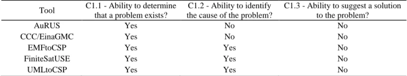
The problem addressing criteria refers to three levels of problem reasoning, as defined by Hartman (2001): the detection of the problem (C1.1), the identification of the cause (C1.2) and the suggestion of a solution (C1.3). Problem detection relates to the ability of the tool to issue a notification when in the presence of a problem. Cause identification relates to the ability to identify the source of the problem. Solution suggestion refers to the ability to advice a solution to correct the error that originates the finite satisfiability problem.
Table 2. Comparison results for problem addressing
Tool C1.1 - Ability to determine that a problem exists?
C1.2 - Ability to identify the cause of the problem?
C1.3 - Ability to suggest a solution to the problem?
AuRUS Yes No No
CCC/EinaGMC Yes No No
EMFtoCSP Yes Yes No
FiniteSatUSE Yes Yes No
UMLtoCSP Yes Yes No
As shown by the results, the approaches embodied by the tools EMFtoCSP, FiniteSatUSE and UMLtoCSP offer the ability to detect the existence of finite satisfiability problems and indicate the cause of the problem.The AuRUS and CCC/EinaGMC tools are only able to indicate the existence of problems, but not the cause.
Currently, no tool provides the ability to suggest a solution to the problem. The absence of this functionality is not resultant of a lack of technical implementation, but an omission present in all the approaches. However, the FiniteSatUSE team is currently undergoing investigation regarding this particular capability (Balaban et al. 2010).
Through the completeness comparison, we determine which approach offers a more complete solution. Thus, the compared characteristics refer to the ability to identify more than one finite satisfiability problem (C2.1) and the ability to present a proof of finite satisfiability when a class diagram does not have finite satisfiability problems (C2.2).
Table 3. Comparison results for completeness
Tool C2.1 - Ability to identify multiple problems?
C2.2 - Ability to present proof of finite satisfiability?
AuRUS No No
CCC/EinaGMC No No
EMFtoCSP Yes Yes
FiniteSatUSE Yes No
UMLtoCSP Yes Yes
The AuRUS and CCC/EinaGMC tools failed to identify the existence of more than one finite satisfiability problem. These tools only provide a feedback regarding the finite satisfiability of the class diagram, regardless of having just one problem or more problems. Contrarily, the EMFtoCSP, FiniteSatUSE and UMLtoCSP are able to provide information about the existence of more than one finite satisfiability problem. Regarding the proof of non-existent problems, only the EMFtoCSP and UMLtoCSP tools comply with this feature, suggesting an object diagram, which represents a possible instance of the class diagram satisfying all constraints and, therefore, finitely satisfiable.
The essential characteristics comparison mainly refers to a set of characteristics that are regarded as essential for a finite satisfiability verification tool (Cabot and Clarisó 2005). These characteristics include the ability to: accept an input perceptible by the user (C3.1) and commonly accepted (e.g. UML/OCL), analyze the diagrams as they are, without requiring additional annotations (C3.2), verify automatically, without the manual interaction of the user (C3.3), provide understandable results (C3.4) and integrate effortlessly in the SDLC (C3.5), without the need of additional time consuming steps.
Table 4. Comparison results of essential characteristics
Tool C3.1 - Accepts as an input a notation understandable by the user? C3.2 - Ability to verify without additional annotations? C3.3 - Automatic verification capability, without user interaction? C3.4 - Provides understandable results for the
user?
C3.5 - Integrates effortlessly in
SDLC?
AuRUS Yes Yes Yes Yes No
CCC/EinaGMC Yes Yes Yes Yes Yes
EMFtoCSP Yes Yes Yes Yes Yes
FiniteSatUSE No Yes Yes Yes No
UMLtoCSP Yes Yes Yes Yes Yes
Regarding the ability to accept a perceptible and commonly used input, only the FiniteSatUSE was considered as not able, because of the use of USE grammar. The use of this tool implies the conversion of the UML class diagrams to USE grammar. Despite the existence of a prototype conversion tool from XMI to USE grammar (Sun et al. 2009), it was not possible to use it with success and some manual conversion work was necessary.
It was observed that all tools were able to verify the diagrams without the use of a specific additional annotation, without user interaction and the results were perceptible and understandable.
The FiniteSatUSE tool was considered as not able to effortlessly integrate in the SDLC due to the conversion problem already mentioned, which involves a time consuming and error prone additional step in contrast to the other tools.
The UML support comparison was defined in order to verify which tools support the most common components present in UML class diagrams. Accordingly, it was verified if the approaches and respective tools supported: binary associations (C4.1), associations n-ary (C4.2), associative classes (C4.3), aggregation (C4. 4), composition (C4.5) and generalization (C4.6).
As shown by the results, the AuRUS and FiniteSatUSE tools do not support n-ary relations. Also, the EMFtoCSP and UMLtoCSP tools do not support aggregation and composition.
Note that this support refers mainly to the loading of the class diagram, rather than the verification process.
Table 5. Comparison results of UML support
Tool C4.1 – Supports binary associations? C4.2 – Supports n-ary associations? C4.3 – Supports associative classes? C4.4 – Supports aggregation? C4.5 – Supports composition? C4.6 – Supports generalization ?
AuRUS Yes No Yes Yes No Yes
CCC/EinaGMC Yes Yes Yes Yes Yes Yes
EMFtoCSP Yes Yes Yes No No Yes
FiniteSatUSE Yes No Yes Yes No Yes
UMLtoCSP Yes Yes Yes No No Yes
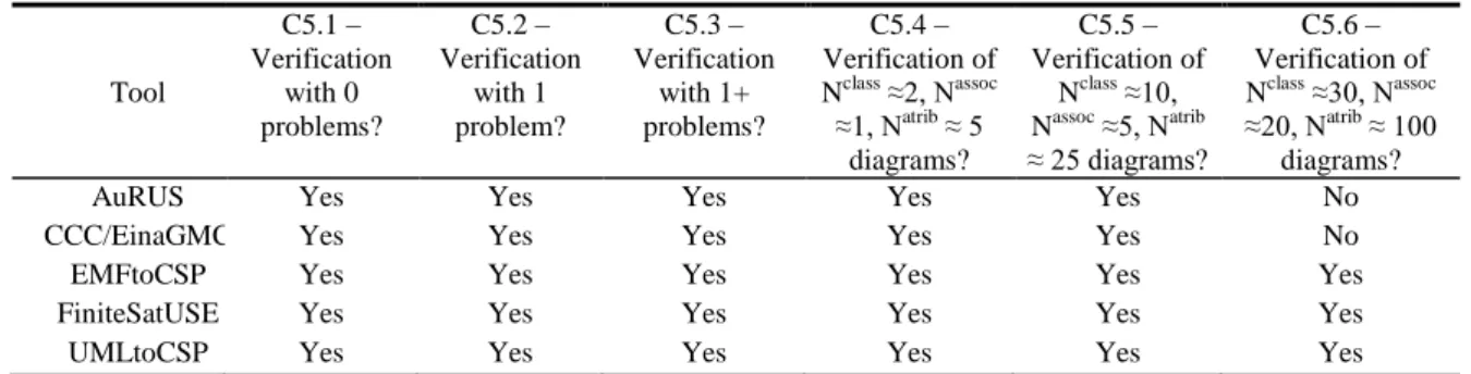
The effectiveness comparison refers to two dimensions: the ability to verify a diagram accordingly to the number of problems and the ability to very accordingly to the dimension of the diagram. Thus, comparison criteria was defined to verify the successful verification in diagrams without problems (C5.1) with only one problem (C5.2) and with more than one problem (C5.3). Additionally, it was verified the verification success in diagrams with different dimensions (C5.4, C5.5 and C5.6). The dimension specifications refer to the number of classes, attributes and associations of the diagrams.
Results show that all tools are effective when verifying diagrams, independently of the number of problems in the diagram. This comparison criterion refers only to the capacity for verifying the diagram and not the fact of being able to indicate the existing problems, as this feature had been tested previously (C2.1).
Table 6. Comparison results for effectiveness Tool C5.1 – Verification with 0 problems? C5.2 – Verification with 1 problem? C5.3 – Verification with 1+ problems? C5.4 – Verification of Nclass ≈2, Nassoc ≈1, Natrib ≈ 5 diagrams? C5.5 – Verification of Nclass ≈10, Nassoc ≈5, Natrib ≈ 25 diagrams? C5.6 – Verification of Nclass ≈30, Nassoc ≈20, Natrib ≈ 100 diagrams?
AuRUS Yes Yes Yes Yes Yes No
CCC/EinaGMC Yes Yes Yes Yes Yes No
EMFtoCSP Yes Yes Yes Yes Yes Yes
FiniteSatUSE Yes Yes Yes Yes Yes Yes
UMLtoCSP Yes Yes Yes Yes Yes Yes
The comparison regarding the verification of diagrams of different dimensions showed some differences between tools. While all tools have been able to load and check the smaller dimension diagrams (C5.4 and C5.5), the AuRUS and CCC/EinaGMC tools did not succeeded in checking the larger dimension diagram (C5.6). However, it was not possible to determine whether the failure is related to a weak technical capacity of the tool for manipulating larger diagrams or an actual limitation of the verification process.
The comparison of the efficiency refers to the time necessary for the verification of finite satisfiability problems in diagrams of different dimensions. The measure is presented in seconds and represents the average value of three consecutive runs.
Table 7. Comparison results for efficiency
Tool
C6.1 – Verification time of Nclass ≈2, Nassoc ≈1, Natrib ≈
5 diagrams?
C6.2 – Verification time of Nclass ≈10, Nassoc ≈5, Natrib ≈
25 diagrams?
C6.3 – Verification time of Nclass ≈30, Nassoc ≈20, Natrib ≈ 100 diagrams? AuRUS 5 s 203 s - CCC/EinaGMC < 1s 107 s - EMFtoCSP < 1s 112 s 3105 s FiniteSatUSE < 1 s 78 s 2720 s UMLtoCSP < 1 s 102 s 3010 s
Regarding the verification of the smaller dimension diagram (C6.1) with the exception of the AuRUS tool, all verification times are less than 1 second. The higher time of the AuRUS may be affected by the fact that this tool is provided through the Internet and subject to inherent network limitations. The verification of the medium-sized diagram (C6.2) presented times from 78 seconds to 203 seconds. The verification of the larger diagram (C6.3) presented a considerable increase of time required to perform the verification, with time values near the 3000 seconds mark. Concerning the AuRUS and CCC/EinaGMC tools, it was not possible to determine the processing time, since this tools were unable to process the diagram.
5. CONCLUSION AND FUTURE WORK
Upon the completion of the comparative study and the analysis of the results, some conclusions can be reached, as well as some additional considerations by the authors. Although most available approaches still have some limitations, it was found that most approaches and respective tools can detect with success the existence of finite satisfiability problems in UML class diagrams.
Taking in account the results of the comparison study, the authors consider the following tools to be the most suitable for the verification of finite satisfiability: EMFtoCSP, UMLtoCSP and FiniteSatUSE. This conclusion takes mainly in account the ability for verifying large diagrams, as well as the capability for identifying more than one finite satisfiability problem and respective causes of the problems. The EinaGMC and AuRUS tools, although considered less suitable, may be recommended for specific scenarios where one only needs to validate the finite satisfiability of small diagrams.
Note that the findings and conclusions reflect the current state of the tools at the time of execution of this comparative study, from September 2011 to June 2012. As most of these tools exist in a prototype mode and are in a permanent state of evolution and development, it is correct to assume that some negative results may be due to the referred permanent state of evolution and it is possible that the repetition of this comparative study in a near future would provide different results.
Additionally, the authors consider that, due to the current state of the art regarding finite satisfiability verification tools and the lack of studies that may indicate significant advantages of adopting the verification of finite satisfiability in the software development life cycle, one should not expect a near future adoption of these tools in professional environments.
In future work, the authors intend to enrich the comparison framework, by defining quantitative scales and new comparison criteria’s, recurring to a joint survey of researchers and specialists in finite satisfiability. By doing so, the authors aim to create a universally accepted comparison framework, used for future comparison and benchmark studies. The authors also intend to pursue studies regarding the impact and acceptance of finite satisfiability verification tools in real work environment.
ACKNOWLEDGEMENT
We would like to acknowledge and extend our gratitude to the following persons, who have helped or contributed in some way to this work: Prof. Mira Balaban, Prof. Lars Hamann, Prof. Ernest Teniente, Prof. Song Eunjee and graduate student Xiyan Cao.
REFERENCES
Apt, K. R. and Wallace, M., 2007. Constraint Logic Programming using ECLiPSe, Cambridge University Press.
Balaban, M. and Maraee, A., 2006. Consistency of UML Class Diagrams with Hierarchy Constraints, Next Generation Information Technologies and Systems - Lecture Notes in Computer Science, Springer Berlin Heidelberg, pp. 71-82.
Balaban, M., Maraee, A. and Sturm, A., 2010. Management of Correctness Problems in UML Class Diagrams - Towards a Pattern-Based Approach. International Journal of Information System Modeling and Design, Vol. 1, No. 4, pp. 24-47.
Berardi, D., Calvanese, D. and Giacomocad, G., 2005. Reasoning on UML class diagrams. Artificial Intelligence, Vol. 168, No. 1, pp. 70–118.
Berrabah, D., Boufarès , F. and Ducateau, C., 2006. A New Tool to Check the Coherence of Constraints Defined on UML Class Diagrams, IJCSNS International Journal of Computer Science and Network Security, Vol.6 Nº 8B.
Berrabah, D. and Boufarès , F., 2008. Constraints Satisfaction Problems in Data Modeling, Proceedings of the 5th International Conference on Soft Computing as Transdisciplinary Science and Technology (IEEE Systems, Man, and Cybernetics Society), Paris, France, pp. 292-297.
Booch, G., Rumbaugh, J. and Jacobson, I., 2005. The Unified Modeling Language User Guide (2nd Edition), Addison-Wesley Professional, USA.
Cabot, J. and Clarisó, R., 2008. UML/OCL Verification in practice. First International Workshop on Challenges in Model-Driven Software Engineering, Toulouse, France, pp. 31-25.
Cabot, J., Clarisó, R. and Riera, D., 2008. Verification of UML/OCL Class Diagrams Using Constraint Programming. International Conference on Software Testing, Verification, and Validation, Lillehammer, Norway.
Cadoli, M., Calvanese, D., De Giacomo, G., and Mancini, T., 2004. Finite satisfiability of UML class diagrams by Constraint Programming. CSP Techniques with Immediate Application (CSPIA), 2. Cadoli, M., Calvanese, D., Giacomo, G. and Mancini, T., 2007. Finite Model Reasoning on UML Class
Diagrams via Constraint Programming. Proceedings of the 10th Congress of the Italian Association for Artificial Intelligence, Italy, pp. 36-47.
Calvanese, D., 1996. Finite Model Reasoning in Description Logics. International Conference on Principles of Knowledge Representation and Reasoning, Massachusetts, U.S.A., pp. 292-303. Dobing, B. and Parsons, J., 2006. How UML is used. Communications of the ACM, Vol. 49, No. 5, pp
109-113.
Farré, C., Teniente, E. and Urpí, T., 2004. A New Approach for Checking Schema Validation Properties, Database and Expert Systems Applications, Lecture Notes in Computer Science, Springer Berlin Heidelberg, pp. 77-86.
Farré, C., Teniente, E. and Urpí ,T., 2005. Checking query containment with the CQC method, Data Knowledge Engineering, Volume 53, Issue 2, pp. 163-223.
GMC, 2010. EinaGMC Start Guide, Technical University of Catalonia and Open University of Catalonia.
Gogolla, M., Büttner, F. and Richters, M., 2007. USE: A UML-Based Specification Environment for Validating UML and OCL, Science of Computer Programming, 69, pp. 27-34.
González, C.A., Buttner, F., Cláriso, R. and Cabot, J., 2012. EMFtoCSP: A Tool for the Lightweight Verification of EMF Models, Formal Methods in Software Engineering: Rigorous and Agile Approaches, Zurich, Switzerland.
Hartmann, S., 2001. Coping with Inconsistent Constraint Specifications. Conceptual Modeling - ER 2001 - 20th International Conference on Conceptual Modeling, Yokohama, Japan, pp. 241-255.
ISO, 1995. IEC 14102: Information Technology - Guideline for the evaluation and selection of CASE tools. International Organization for Standardization, Geneva, Switzerland.
Kovse, J., and Härder, T., 2002. Generic XMI-based UML model transformations. Object-Oriented Information Systems, Springer Berlin Heidelberg, pp. 192-198.
Lange, C.F.J. and Chaudron, M.R.V., 2006. Effects of defects in UML models: an experimental investigation, Proceedings of the 28th international conference on Software engineering, Shangai, China, pp. 401-411.
Lenzerini, M. and Nobili, P., 1990. On the satisfiability of dependency constraints in entity-relationship schemata, Information Systems, Volume 15, Issue 4, pp. 453-461.
Maraee, A. and Balaban, M., 2007. Efficient Reasoning about Finite Satisfiability of UML Class Diagrams with Constrained Generalization Sets, Model Driven Architecture-Foundations and Applications, Springer Berlin Heidelberg, pp. 17-31.
Maraee, A., Makarenkov, V. and Balaban, M., 2008. Efficient Recognition and Detection of Finite Satisfiability Problems in UML Class Diagrams: Handling Constrained Generalization Sets, Qualifiers and Association Class Constraints, Model Co-evolution and Consistency Management MCCM’08, Toulouse, France.
Marriott, K. and Stuckey, P. J., 1998. Programming with Constraints: An Introduction, MIT Press, Cambridge, Massachussetts,
McAffer, J. and Lemieux, J., 2005. Eclipse Rich Client Platform: Designing, Coding, and Packaging Java, Addison-Wesley Professional.
Mellor, S. J., Clark, A. N. and Futagami, T., 2003. Model-driven development. IEEE software, pp. 14-18.
Mellor, S. J., Scott, K., Uhl, A., and Weise, D., 2002. Model-driven architecture. Advances in Object-Oriented Information Systems, Springer Berlin Heidelberg, pp. 290-297.
Queralt, A., 2009. Validation of UML conceptual schemas with OCL constraints and operation. PhD Thesis, Polytechnic University of Catalonia.
Queralt, A., Rull, G., Teniente, E., Farré, C. and Urpí, T., 2010. AuRUS: Automated Reasoning on UML/OCL Schemas. International Conference on Conceptual Modeling, Vancouver, Canada, pp. 438-444.
Queralt, A. and Teniente, E., 2006. Reasoning on UML Class Diagrams with OCL Constraints, Conceptual Modeling - ER 2006, Vol. 4251, pp. 497-512.
Richters, M., and Gogolla, M., 1998. On formalizing the UML object constraint language OCL. Conceptual Modeling–ER’98, Springer Berlin Heidelberg, pp. 449-464.
Rumbaugh, J., Jacobson, I. and Booch, G., 1999. The Unified Modeling Language Reference Manual, Addison-Wesley Professional, USA.
Russell, S. and Norvig, P., 2009. Artificial Intelligence: A Modern Approach, 3rd Edition, Prentice Hall Shaikh, A., Wiil, U. K. and Memon, N., 2011. Evaluation of Tools and Slicing Techniques for Efficient
Verification of UML/OCL Class Diagrams. Advances in Software Engineering, Vol. 2011, No. 5, pp. 1-18.
Sun, W., Song, E., Grabow, P. and Simmonds, D., 2009. XMI2USE: A Tool for Transforming XMI to USE Specifications. Advances in Conceptual Modeling-Challenging Perspectives, pp. 147-156. Unhelkar, B., 2005. Verification and Validation for Quality of UML 2.0 Models. Wiley-Interscience,