Abstract
This paper presents a methodology for the conceptual design of a Maneuver Load Control system taking into account the airframe flexibility. The system, when switched on, is able to minimize the bending moment augmentation at a wing station near the wing root during an unsteady longitudinal maneuver. The reduction of the incremental wing bending moment due to maneuvers can lead to benefits such as improved pay-loads/gross weight capabilities and/or extended structural fatigue life. The maneuver is performed by following a desired vertical load factor law with elevators deflec-tions, starting from the trim equilibrium in level flight. The system observes load factor and structural bending through accelerometers and calibrated strain sensors and then sends signals to a computer that symmetrically actuates ailerons for reducing the structural bending and elevators for compensating the perturbation to the longitudinal equilibrium. The major limit of this kind of systems appears when it has to be installed on commercial transport air-craft for reduced OEW or augmented wing aspect-ratio. In this case extensive RAMS analyses and high redundancy of the MLC related sub-systems are required by the Certification Authority. Otherwise the structural design must be performed at system off. Thus the unique actual benefit to be gained from the adoption of a MLC system on a commercial transport is the fatigue life extension. An application to a business aircraft responding to the EASA Certifica-tion SpecificaCertifica-tions, Part 25, has been performed. The aircraft used for the numerical application is considered only as a test case-study. Most of design and analysis considerations are applicable also to other aircraft, such as unmanned or military ones, although some design requirements can be clearly different. The estimation of the fatigue life extension of a structural joint (wing lower skin-stringer), located close to the wing root, has been estimated by showing the expected benefit to be gained from the adoption of such a maneuvering load control system.
Keywords
Load control, Aeroelasticity, Aircraft.
Concept of a Maneuvering Load Control System
and Effect on the Fatigue Life Extension
N. Paletta a
D. Cristillo b
M. Belardo c
A. Marino d
M. Pecora e
a The Italian Aerospace Research Centre,
CIRA SCpA Via Maiorise snc, 81043 Capua (CE), Italy
b The Italian Aerospace Research Centre,
CIRA SCpA Via Maiorise snc, 81043 Capua (CE), Italy
c The Italian Aerospace Research Centre,
CIRA SCpA Via Maiorise snc, 81043 Capua (CE), Italy
d The Italian Aerospace Research Centre,
CIRA SCpA Via Maiorise snc, 81043 Capua (CE), Italy
e The Italian Aerospace Research Centre,
CIRA SCpA Via Maiorise snc, 81043 Capua (CE), Italy
http://dx.doi.org/10.1590/1679-78252512
1 INTRODUCTION
Several aircraft manufacturers have been conducting for many years research in the area of active controls, that are becoming increasingly important in the design of modern aircraft. Nowadays ac-tive control systems drive the constructing architecture and the configuration of the whole aircraft by affecting operative mission feasibility and flight performances. Thus the adoption of active con-trol systems plays an essential role since the early stages of design. The choice to equip an airplane with active controls modifies the design philosophy approach also from a certification viewpoint. The vehicle must be able to take on board a set of equipment such as
1.Sensors aimed at measuring what has to be observed or controlled; 2.On-board computers;
3.Fly-By-Wire (FBW) controls;
4.Electro-mechanic and/or electro-hydraulic actuators;
5.Classic or advanced aerodynamic controls (control surfaces, control jets, etc.).
2 MANEUVER LOADS CONTROLLING STRATEGY
Several Feedback Control Systems (FCS) are currently installed on civilian and military aircraft. Some of them are aimed at increasing the airplane stability and others at controlling flight parame-ters (such as autopilot systems). The most used types of FCSs to alleviate inherent stability prob-lems or to control flight parameters are:
Angle of Attack Feedback to the longitudinal controls (elevators or canards);
Load factor feedback to the longitudinal controls (elevators or canards);
Angle of sideslip feedback to the directional controls (rudders).
The LAS object of this work is aimed at obtaining wing bending reduction at a specific Wing Control Station (WCS) usually near the wing root, but by attaining always the same design vertical load factor. To accomplish this objective, the LAS incorporates a Load Factor Feedback (LFF) to the elevators in order to perform a longitudinal maneuver by automatically following the desired load factor time history. The MLC is accomplished by observing the bending at the wing root sta-tion and acting on the load alleviators (dedicated control surfaces rather than ailerons and/or flaps) in order to shift the wing center of pressure inboard.
Figure 1: LAS Macro-System.
The structural load reduction can be carried-out in two alternative ways:
1.By activating the MLC when the bending reaches a specified absolute value (less than the limit design value with MLC-off);
2.By using a reference signal identically zero for the incremental bending so that the MLC im-mediately acts when the acting load exceeds the reference 1-g bending. Such reference is not a unique value, it is represented by a range of values, to be calculated for a combination of dif-ferent flight conditions (Mach number versus altitude for each mass condition).
The main practical issue is related to the bending moment observation. This can be accom-plished by means of strain gages measurements, as illustrated in literature (Aiken (1948), Rauscher (1984), Di Palma (2007)). Experimental ground calibrations are needed in order to correlate all strain gage signals to the bending moment acting on the wing control station (Skopinski (1953), Jenkins (2007) and Lokos (2002 and 2004). The load factor is kept compliant with the desired refer-ence signal whether or not the MLC is switched on or off since the load factor perturbation is con-trolled and minimized by the action of the LFF. On the other hand the LFF acts on the
longitudi-LAS
nal control by deflecting elevators and thus by varying angle of attack and other flight parameters that affect the wing root bending.
3 AEROELASTIC THEORETICAL MODEL
Longitudinal and unsteady maneuvers are developed by using the methodology presented by Paletta et al. (2010), taking into account the airframe flexibility by means of a modal approach, typical of the Dynamic Aeroelasticity domain. Normal Modes are used extensively in the dynamic analyses of airplane responses, including investigations into aeroelastic instabilities such as flutter. This approach allows the solution of a generic structural static problem without fixing a suitable number of constraints: the airplane can be considered unrestrained.
3.1 A Sub-Section
The theoretical model is based on the general equation of the dynamic Aeroelasticity in a modal approach, for a symmetric maneuver (Eq.(1), a system of N+2 differential equations of motion, where N is the number of elastic modes).
ì é ù é ù é ù ü é ù
ï ï
ï ê ú + ê ú +ê ú êï ú =
í ê ú ê ú ê ú êý ú
ï ê ú ê ú ê ú êï ú
ï ë û ï
î ë û ë û þ ë û
é ù é ù é ù
ê ú ê ú ê ú
= ê ú ê ú+ ê ú
ê ú êë úû êë úû
ë û
2
2 2
0 0 0 0 ( )
0
( ) ( )
0 0 0 ( )
( ) 1 1 ( ) ( ) 2 2 R RR
EE EE EE E
R R RR RE E E ER EE q j m j j
m K q j
Q Q q j q
V V j
Q Q q j q
d
d
w
w w s w
w
r w r d w (1)
where single and double underlines denote respectively vectors and tensors. Eq. (1) is written by distinguishing rigid and elastic modes through subscripts R and E. The components of q are the degrees of freedom of the airplane: the plunge and the pitch mode. Q is the quasi-steady generalized aerodynamic forces matrix, ρ is the air density, V is the aircraft velocity, m is the generalized mass matrix, ϭ is the damping coefficient matrix, K is the generalized stiffness matrix, j is the imag-inary part of quantity, ω is the circular frequency, and δ is the elevator deflection.
Eq. (1) can be written in the time domain and by making some positions and substitutions (like in Paletta et al. (2010)) becomes:
= 0, + 1, + 0,EC + 0,Eq + 0Eext
E ER R ER R
q F q F q F d F F (2)
+ + = + +
R ˆ R ˆ R extq ext0 C ( )
RR RR RR
m q C q K q F F F dt (3)
In which, all matrix are used to obtain elastic generalized coordinates starting from rigid gener-alized coordinates. F0Eext and Fext0 represents possible external forces, F0,Eqand Fextqare the
aero-dynamic terms depending exclusively on the aero-dynamic pressure, F0,ECand FCare the forces to
de-flect the ailerons.
is possible to write the same equations by involving two or more controls (i.e. the elevator and the load alleviator for an alleviated maneuver), by simply changing some formal notations.
3.2 Open-Loop State-Space Model
The airplane, in level flight, is modeled by means of a state-space system aimed at simulating un-steady longitudinal maneuvers. Since the objective of the work is to control load factor and bending by feeding-back the system to elevators and ailerons, the state-space representation is chosen be-cause of its straight forward implementation with commercial tools such as Matlab and Simulink®. By introducing the load alleviator control (i.e. a symmetrical deflection of ailerons), Eq. (3)) be-comes:
+ + = + + +
R ˆ R ˆ R extq ext0 C ( ) CC ( )
RR RR RR
m q C q K q F F F dt F bt (4)
here
F
C andF
CC contain respectively the force coefficients for elevator and aileron controls, β isthe load alleviation control surface deflection. By choosing the state as
R
R
q
x
q
é
ù
ê
ú
= ê ú
ê
ú
ë
û
(5)and the input as
u
d
b
é ù
ê ú
= ê ú
ê ú
ë û
(6)Eq. (4) can be written in the controllable canonical form
x
=
Ax
+
B u
(7)with
1 1
0
ˆ
ˆ
RR RR RR RR
I
A
m
-K
m
-C
é
ù
ê
ú
= ê
-
-
ú
ê
ú
ë
û
(8)
and
1 1
0
0
C CC
RR RR
B
m
-F
m
-F
é
ù
ê
ú
= ê
-
-
ú
ê
ú
ë
û
(9)
altitude, Mach number and mass condition) at the WCS by following the procedure presented by Paletta et al. (2010).With the same symbol meanings
(10)
Where α is the angle of attack and h is plunge angle. By taking the following positions:
T T T
h h h h
T T T
h h h h
T
LD
S
M
T
LD
S
M
T
LD
S
M
T
LD
S
M
T
LD
S
M
T
LD
S
M
T
LD
S
M
T
a a a a d d d d
a a a a b b b b
a a a a
é
ù
é
ù
é
ù
=
ê
ë
ú
û
=
ê
ë
ú
û
=
ê
ë
ú
û
é
ù
é
ù
é
ù
=
ê
ë
ú
û
=
ê
ë
ú
û
=
ê
ë
ú
û
é
ù
= ê
ë
ú
û
(11) 1 2 3
0
h hK
LD
K
LD
LD
K
LD
LD
a
a
a
é
ù
= ê
ë
ú
û
é
ù
= ê
ë
ú
û
é
ù
= ê
ë
ú
û
(12)
1
1 1 3
1
2 2 3
1 1 3 1 2 3
ˆ
ˆ
p RR RR
p RR RR
p RR C
p RR CC
K
K
K m
K
K
K
K m
K
C
LD
K m
F
C
LD
K m
F
d b
-=
-=
-=
+
=
+
(13) 00
ail R h R
HM
=
HM
+
ê
é
ë
HM
aú
û
ù
q
+
ë
é
ê
HM
HM
aú
ù
û
q
(14)the output equation is written as follows:
y
=
C x
+
D u
(15)with
1 2
1
ˆ
1ˆ
0
p p
RR RR RR RR
h
K
K
C
m
K
m
C
HM
aHM
HM
a-
-é
ù
ê
ú
ê
ú
ê
ú
= -
ê
-
ú
é
ù é
ù
ê
ê
ú ê
ú
ú
ê
ë
û ë
û
ú
ë
û
and
1 2
1 1
p p
C CC
RR RR
C C
D m F m F
HMd HMb
-
-é ù
ê ú
ê ú
= ê ú
ê ú
ê ú
ê ú
ë û
(17)
Eqs. (7)-(9) together with Eqs. (15)-(17) represent the Multi Input – Multi Output (MIMO) state-space system of the airplane in longitudinal flight.
It results
2 3
4
rank B AB A B A B
é
ê
ù =
ú
ë
û
(18)and
2
3 3
C
C A rank
C A
C A
é ù ê ú ê ú ê ú ê ú = ê ú ê ú ê ú ê ú ê ú ë û
(19)
that is the system has full state controllability whereas it is not completely observable (in its first state).
4 MLC SYSTEM: APPLICATION TO A CS-25 BUSINESS JET
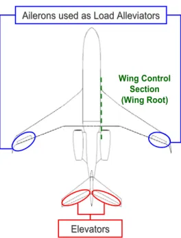
The aircraft used for the numerical application is a business jet responding to the EASA Certifica-tion SpecificaCertifica-tions Part 25. The aircraft top view is shown in Figure 2. The maximum vertical load factor is 2.5, whereas the chosen WCS is at the wing root. The aeroelastic model is made up of an aerodynamic model for Doublet Lattice Method (DLM) calculations, a dynamic model and a match-ing model (see Figure 3).The dynamic model is of stick-beam type for wmatch-ing, fuselage and tail-planes while the junctions are modeled by means of direct matrix input simulating stiffness and inertia behaviour (Nastran DMIG matrices). Winglets and nacelles are considered rigid. The inertia is modelled by a set of concentrated masses with their own moments of inertia. The matching model – link between aerodynamics and structure – is made up of a set of grids (Interface Grids) for load and displacement interpolations.
Load derivatives and matrices ˆ RR
C and ˆ RR
K . The airplane flexibility is taken into account by
con-sidering the first 37 symmetric normal modes.
Figure 2: Aircraft platform, elevators and ailerons used as load alleviators.
Figure 3: Numerical Models (blue: aerodynamics, red: structural and inertia models).
Ailerons used as Load Alleviators Ailerons used as Load Alleviators
Elevators Elevators
4.1 Feedback Control System Architecture
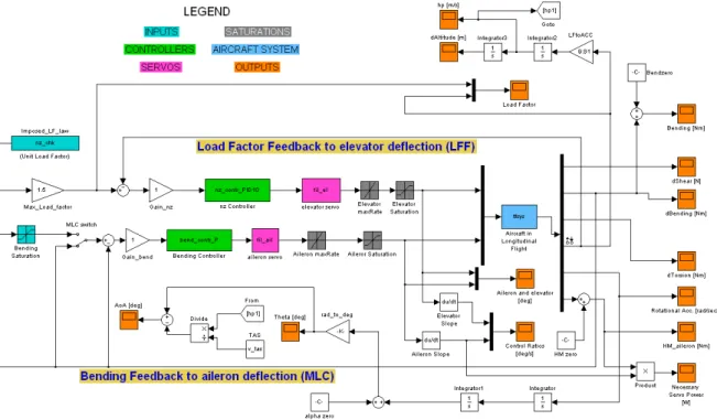
The FCS architecture is shown by the SIMULINK® schematic of Figure 4. The whole system is made up of two feedback SISO systems, simulating the Load Factor Feedback and the MLC sys-tem. The light blue block represents the aircraft dynamics in longitudinal flight (plant) and magen-ta blocks simulate the servo dynamics. The transfer function adopted to model both servos is the following:
7.994e004 --- s^2 + 282.7 s + 7.994e004
which means a natural frequency of 45 Hz and a damping ratio of 0.5. Cyan blocks are the inputs for the system. The “MLC switch” is used to activate the MLC system. Once a load factor time history is established, only minimum and maximum WCS Bending moments have to be imposed. This is done by putting these values in the “Bending Saturation” block in order to give an allowable load range.
Grey blocks simulate saturations due to mechanical stops and maximum allowable deflection rates. Being the MLC using ailerons as load alleviators, it has to be in series with the roll control system in order to preserve lateral manoeuvrability, thus symmetric MLC deflections are additive to the anti-symmetric roll deflections until the mechanical control surface stops are reached. The MLC servo authority limits are established as 15 degrees trailing edge up and down. The maximum allowable deflection rate is chosen as ±30 degrees per second.
Orange blocks are the outputs of the system. Although the linear system is built with only six outputs, other flight parameters are evaluated by external integrations, derivations and/or multipli-cations.
4.2 LFF and MLC Controllers: Requirements and Synthesis
Three types of system performance specifications (requirements) have been considered (Roskam (2009)):
Frequency domain specifications;
Time domain specifications;
Error specifications.
As regards the frequency domain specifications, a gain margin of a factor of 2 and a phase mar-gins larger than 35 degrees are fixed. System time domain specifications are given in terms of the response of the system to a unit step input: Overshoot (5% of the steady-state output for Margin of Safety Policy reasons), Rise Time (a performance requirement, 0.25 s for the LFF system and 0.10 s for the MLC system) and Settling Time (1.0 sec. to reach and remain within a 2 percent of its final value) are the adopted time domain specifications. The last specification regards the Position Error
( )
e ¥ requirement. Considering a negative feedback system subject to a unit step input, the
Posi-tion Error is the difference between the unity and the steady-state response (C(s) for s ¥ ). For
the present application, the Position Error related to the LFF system has to be zero.
4.2.1 LFF Controller Synthesis
In order to fulfill all the requirements, the load factor is fed-back to the elevator deflection by using a negative feedback with a PID (Proportional Integral Derivative) controller. The controller synthe-sis is done by applying the tuning method presented Skogestad (2004) and implemented in Matlab® through the SISOTOOL® graphic user interface. The PID controller of the LFF system is designed (by tuning all constants KP, Ti, Td) for each flight case by taking into account the
flexi-bility of the aircraft. The same controller is adopted also in the case of rigid aircraft by simply re-ducing the proportional constant KP according to the stability requirements presented so far. For conciseness reasons all the diagrams showing the dependencies of PID parameters upon dynamic pressure, Mach number and mass condition are not reported. About the dependency upon the dy-namic pressure, KP decreases when the dynamic pressure increases in a quite linear manner. The
most evident result is the dependency of KP for rigid aircraft much less marked if compared with
KP for elastic aircraft. The dependency upon the Mach number is analogous for both rigid and
elas-tic aircraft: KP increases when Mach number increases. The trend results quite quadratic. Any
ap-preciable differences in the dependency of PID parameters upon mass conditions between rigid and elastic aircraft are registered.
4.2.2 MLC Controller Synthesis
designed for each flight case for both rigid and elastic aircraft by simply tuning the proportional constant KP in order to fulfill all the specifications presented so far. As done for the LFF controller,
the gain of the MLC P controller has to be continuously varied in flight in order to keep the specifi-cations fulfilled. Also in this case it could be done by an inboard computer interpolating the calcu-lated data at each flight condition. For sake of conciseness all the diagrams showing the dependen-cies of the controller gain upon dynamic pressure, Mach number and mass condition are not report-ed. It results that the dependency of the gain P upon the dynamic pressure has a quite linear be-haviour with a negative trend; in the case of rigid aircraft it is slightly more marked if compared with the case of elastic aircraft. This happens because the loss of ailerons effectiveness due to flexi-bility partially alleviates the stronger aerodynamics associated with an increasing dynamic pressure. The dependency upon the Mach number is similar, but the difference between rigid and elastic air-craft is more evident.
4.3 Performance of the Maneuver Load Control system – The Effect of Aeroelasticity
In this section an unsteady maneuver similar to a checked maneuver is presented. The performance of the Maneuver Load Control system is measured by the Alleviation Factor (AF) parameter (Eq. (20)). It specifies the percentage of the maneuver incremental load reduction in a specific control section. Since the load characteristic to be alleviated is the bending moment (B), AF is calculated as follows:
100
ALL
B B
AF
B
D - D
= ⋅
D (20)
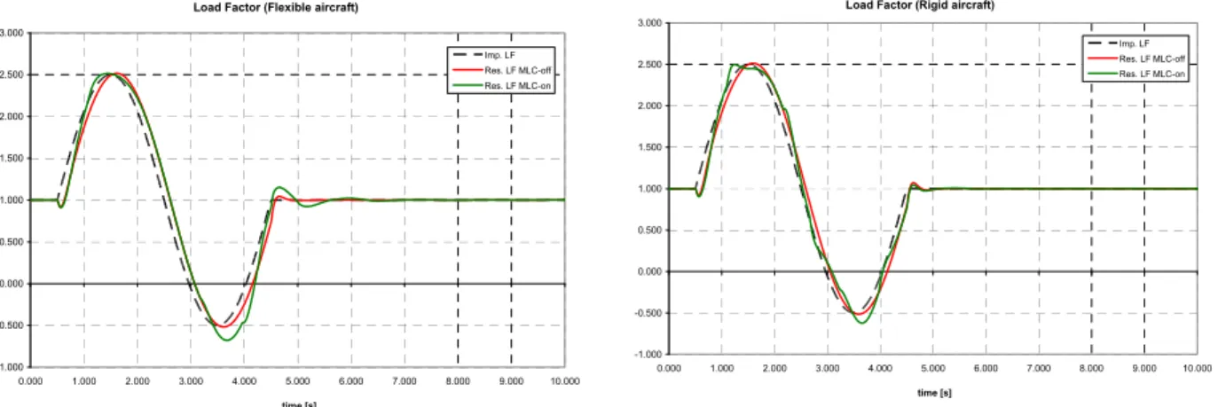
As shown in Figure 5, for elastic and rigid aircraft, the LFF system succeeds in following the desired load factor also when MLC is switched on, despite the symmetric aileron deflection helps the elevator in pitching up the airplane and thus in reaching the load factor peak earlier.
Figure 5: Vertical Load Factor, Comparison between Elastic and Rigid aircraft.
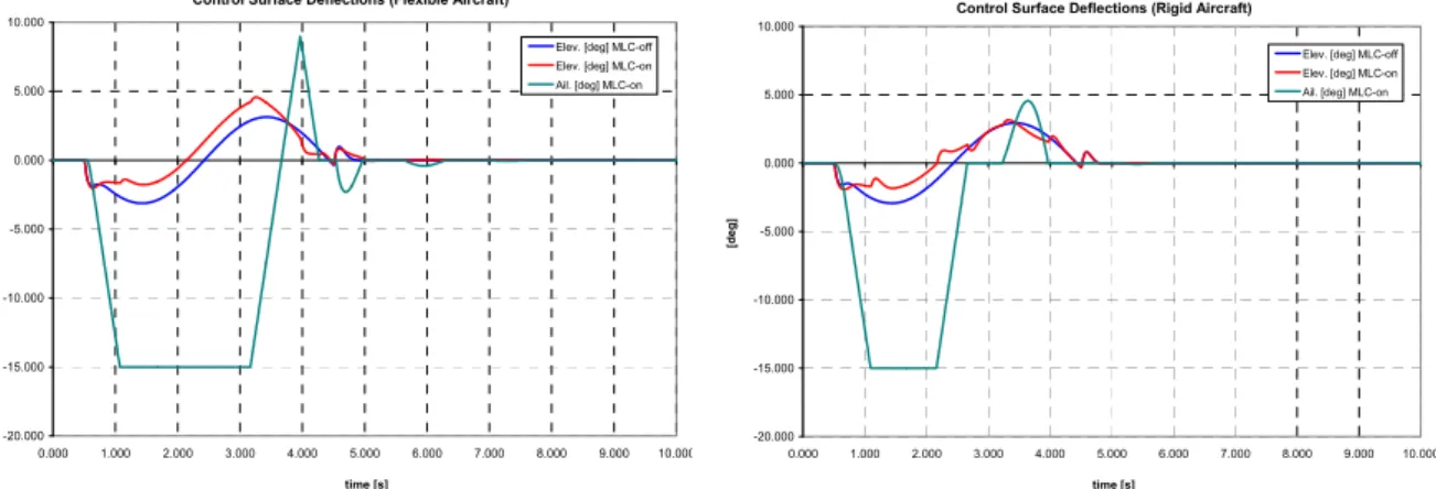
Figure 6 shows the control surface deflection time histories, for elastic and rigid aircraft, for both MLC-on and off. Notice that the necessary load alleviator deflection in the case of flexible
Load Factor (Flexible aircraft)
-1.000 -0.500 0.000 0.500 1.000 1.500 2.000 2.500 3.000
0.000 1.000 2.000 3.000 4.000 5.000 6.000 7.000 8.000 9.000 10.000
time [s]
Imp. LF Res. LF MLC-off Res. LF MLC-on
Load Factor (Rigid aircraft)
-1.000 -0.500 0.000 0.500 1.000 1.500 2.000 2.500 3.000
0.000 1.000 2.000 3.000 4.000 5.000 6.000 7.000 8.000 9.000 10.000
time [s]
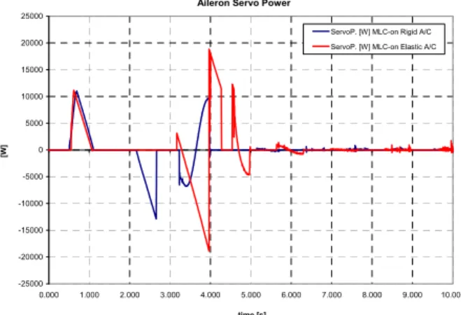
aircraft is greater than in the case of rigid aircraft. This is due to the loss of effectiveness of the outboard ailerons used as load alleviators. The same reason also drives the increase of the necessary servo power to actuate the load alleviators (see Figure 8). The calculated necessary extra power for elastic aircraft is about 60% higher than that calculated for rigid aircraft. Although the aileron hinge moment with rigid aircraft is slightly higher than that calculated for elastic aircraft (see Fig-ure 7), in this latter case the MLC actuation is much more fast, thus leading to a higher deflection angular velocity and a higher necessary servo power.
Figure 6: Control Surface deflections, Comparison between Elastic and Rigid aircraft.
The dependencies of AF upon M, q and aircraft weight (fuel) are depicted in Figure 9 to Figure 11 for both rigid and elastic aircraft. At fixed Mach number, greater the dynamic pressure, more effective the LAS (Figure 5). The gap between rigid and elastic aircraft increases with the dynamic pressure.
Figure 7: Aileron Hinge Moments, Comparison between Elastic and Rigid aircraft.
The LAS effectiveness augmentation with Mach number is less marked than with the dynamic pressure (Figure 6). In case of elastic aircraft, such a dependency becomes smoother.
Control Surface Deflections (Flexible Aircraft)
-20.000 -15.000 -10.000 -5.000 0.000 5.000 10.000
0.000 1.000 2.000 3.000 4.000 5.000 6.000 7.000 8.000 9.000 10.000
time [s]
[d
eg
]
Elev. [deg] MLC-off Elev. [deg] MLC-on Ail. [deg] MLC-on
Control Surface Deflections (Rigid Aircraft)
-20.000 -15.000 -10.000 -5.000 0.000 5.000 10.000
0.000 1.000 2.000 3.000 4.000 5.000 6.000 7.000 8.000 9.000 10.000
time [s]
[d
eg
]
Elev. [deg] MLC-off Elev. [deg] MLC-on Ail. [deg] MLC-on
Aileron Hinge Moments (Flexible Aircraft)
-700.00 -600.00 -500.00 -400.00 -300.00 -200.00 -100.00 0.00 100.00 200.00
0.000 1.000 2.000 3.000 4.000 5.000 6.000 7.000 8.000 9.000 10.00
time [s]
[N
m
]
HM ail. [Nm] MLC-off HM ail. [Nm] MLC-on
Aileron Hinge Moments (Rigid Aircraft)
-600 -500 -400 -300 -200 -100 0 100
0.000 1.000 2.000 3.000 4.000 5.000 6.000 7.000 8.000 9.000 10.000
time [s]
[N
m
]
Figure 7 shows the dependency of AF upon mass conditions: the trend appears quite linear. This behaviour repeats at different flight conditions (i.e. different Mach number and dynamic pressures). The analysis performed underlines that percent errors are relatively low so that this model can be considered sufficiently reliable to characterize the performance of the MLC system for a wide range of flight conditions in a conceptual design phase.
Figure 8: Aileron Necessary Servo Power. Figure 9: Alleviation Factor AF, dependency upon the Dynamic Pressure.
Figure 10: Alleviation Factor AF, dependency upon the Mach Number.
Figure 11: Alleviation Factor AF, dependency upon mass conditions.
5 FATIGUE LIFE EXTENSION DUE TO A MLC SYSTEM
As often highlighted in the previous sections, the reduction in structural internal wing loads due to the adoption of a MLC system can be motivated by the requirement of reaching enhanced perfor-mance. The major limit of this kind of systems appears when it has to be installed on commercial
= . E‐ ‐ . E‐ + . E‐ R = . E+ = ‐ . E‐ + . E‐ ‐ . E‐
R = . E‐
. . . . . . . . . . . . . . .
Dy a i Pressure [Pa]
AF
[%
]
Se sitivit ve sus the D a i P essu e M= . ‐ Elasti A/C Se sitivit ve sus the D a i P essu e M= . ‐ Rigid A/C
= ‐ . + . R = . = ‐ . + .
R = .
. . . . . . . . Fuel % ass AF [% ] AF el # AF ig #
Li ea Fitti g Cu ve AF el # Li ea Fitti g Cu ve AF ig #
= ‐ . E+ + . E+ ‐ . E+ + . E+ R = . E+
= . E+ ‐ . E+ + . E+ ‐ . E+ R = . E+
. . . . . . . . .
Ma h Nu er
AF
[%
]
Se sitivit ve sus the Ma h Nu e = . Pa ‐ Elasti A/C Se sitivit ve sus the Ma h Nu e = . Pa ‐ Rigid A/C
Aileron Servo Power
-25000 -20000 -15000 -10000 -5000 0 5000 10000 15000 20000 25000
0.000 1.000 2.000 3.000 4.000 5.000 6.000 7.000 8.000 9.000 10.000
time [s]
[W
]
analyses and high redundancy of the MLC related sub-systems are required by the Certification Authority. Otherwise the structural design must be performed at system off. Thus the unique actu-al benefit to be gained from the adoption of a MLC system on a commerciactu-al transport is the fatigue life extension. The present section is focused on the estimation of the fatigue life extension of a structural joint (wing lower skin-stringer) located close to the wing root.
5.1 Analysis Strategy
Analyses are carried-out for both cases of MLC-on and MLC-off in order to appreciate the benefit of having an MLC system in terms of structural fatigue life improvement. Hypotheses of this work are: 1.When MLC is switched on, the airplane is in level flight with a wing root bending alleviation
of 10% (AF=0.1);
2.If a gust front is going to be encountered, the MLC is switched-off and load alleviators (con-trol surfaces) are blocked to the last position for keeping the static load alleviation constant during the turbulence;
5.2 Determination of Cumulative Frequency Load Distributions
The fatigue life of civil aircraft wing structures is related to the variations in stress experienced under the following five main types of loading:
1.Gust Loads;
2.In-flight maneuver loads; 3.Ground maneuver loads;
4.The once-per-flight loads resulting from the difference between in-flight and on-ground load levels, usually termed the Ground-Air-Ground (GAG)-cycle;
5.Local loads such as those arising from flaps, undercarriages, etc.
The method to determine the cumulative frequency of occurrence of loads 1 and 2 are presented in ESDU 69023 (1989) whereas for loads 3 in ESDU 75008 (1984). The GAG-cycle (load type 4) is derived from the in-flight gust and maneuver spectrum and the ground maneuver cumulative fre-quency distributions as described in ESDU 79024 (1979). Loads 5 are special cases not accounted for in the damage calculation presented herein. For sake of conciseness all the calculations regarding these kind of analysis are not reported.
5.3 Contributions to the Cumulative Damage – Fatigue Life
0.2615 MPa. Since the entire work is focused on the life extension to be gained from the adoption of a MLC system, the S-N curve provided by ESDU 79024 (1979) is used. It is depicted in Figure 12.
Figure 12: Adopted S-N Curves.
5.4 Cumulative Damage Calculation – Fatigue Life Estimation
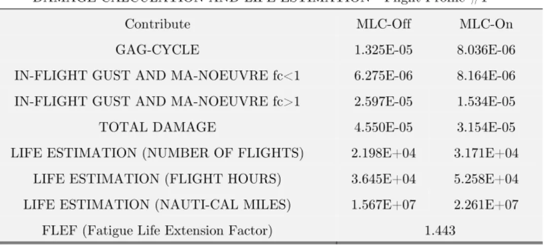
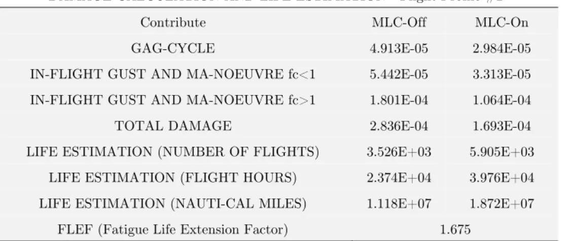
The total damage together with the estimated mean life are listed in Table 1for flight profile #1 (Short Range Mission) and in Table 2 for flight profile #2 (Long Range Mission). The life estima-tion, in number of flights, is calculated as the inverse of the total damage since it is assumed that the failure occurs when ΣD=1.0. Notice that the fatigue life is longer in case of short range mission (flight profile #1) because the airplane flights carrying a very small amount of fuel if compared to the that of the long range mission. The FLEFs (Fatigue Life Extension Factors) are in either case much greater than the unity, indicating a very good life extension, beyond the best expectations.
DAMAGE CALCULATION AND LIFE ESTIMATION - Flight Profile #1
Contribute MLC-Off MLC-On
GAG-CYCLE 1.325E-05 8.036E-06
IN-FLIGHT GUST AND MA-NOEUVRE fc<1 6.275E-06 8.164E-06
IN-FLIGHT GUST AND MA-NOEUVRE fc>1 2.597E-05 1.534E-05
TOTAL DAMAGE 4.550E-05 3.154E-05
LIFE ESTIMATION (NUMBER OF FLIGHTS) 2.198E+04 3.171E+04
LIFE ESTIMATION (FLIGHT HOURS) 3.645E+04 5.258E+04
LIFE ESTIMATION (NAUTI-CAL MILES) 1.567E+07 2.261E+07
FLEF (Fatigue Life Extension Factor) 1.443
DAMAGE CALCULATION AND LIFE ESTIMATION - Flight Profile #2
Contribute MLC-Off MLC-On
GAG-CYCLE 4.913E-05 2.984E-05
IN-FLIGHT GUST AND MA-NOEUVRE fc<1 5.442E-05 3.313E-05
IN-FLIGHT GUST AND MA-NOEUVRE fc>1 1.801E-04 1.064E-04
TOTAL DAMAGE 2.836E-04 1.693E-04
LIFE ESTIMATION (NUMBER OF FLIGHTS) 3.526E+03 5.905E+03
LIFE ESTIMATION (FLIGHT HOURS) 2.374E+04 3.976E+04
LIFE ESTIMATION (NAUTI-CAL MILES) 1.118E+07 1.872E+07
FLEF (Fatigue Life Extension Factor) 1.675
Table 2: Damage Calculation and Life Estimation – Flight Profile #2.
6 CONCLUSION REMARKS
re-gards the fatigue life extension. It should be noted that the impact on aircraft aerodynamic drag due to the activation of a LAS has been never accounted for in the present study. Indeed the load alleviators deflection produces a change in the spanwise aerodynamic distribution with consequent variation of the induced drag. Moreover if the load alleviation is carried-out by shifting the aerody-namic center of pressure inboard, the induced drag probably increases. Furthermore the airfoil camber augmentation leads to a wake drag increase and also to a wave drag increase at high Mach numbers.
References
Bendixen, G. E., O’Connell, R. F. and Siegert, C. D. (1981). Digital Active Control System for Load Alleviation for the Lockheed L-1011. Aeronautical Journal, Vol. 86, No. 849.
ESDU 69023 (1989). Average Gust Frequencies Subsonic Transport Aircraft. ESDU International, ISBN 0 85679 259 4.
ESDU 75008 (1994). Frequencies of Vertical and Lateral Load Factors resulting from Ground Manoeuvres of Air-craft. ESDU International, ISBN 0 85679 109-1.
ESDU 79024 (1979). Estimation of the Endurance of Civil Aircraft Wing Structures. ESDU International, ISBN 0 85679 272 1.
Hahn, K.-U. Koenig, R. (1992). ATTAS flight test and simulation results of the advanced gust management system LARS. AIAA Atmospheric Flight Mechanics Conference, Hilton Head Island, SC.
NASA Contractor Report 3164 (1980). Selected Advanced Aerodynamics and Active Control Technology Concepts Development on a Derivative B-747 Aircraft. NASA Langley Research Center under Contract NAS1-14741 with The Boeing Commercial Airplane Company.
O’Connell, R. F. (1980). Design, Development and Implementation of an Active Control System for Load Alleviation for a Commercial Transport Airplane. AGARD-R-683.
Paletta, N., Belardo, M., Di Palma, L., and Pecora, M., (2013). Evaluation Of Wing Loads During The Flight Drop Test Of The Italian Unmanned Space Vehicle. Proceedings of 5th International Operational Modal Analysis Confer-ence.
Paletta, N., Belardo, M., Pecora, M., (2010). Load Alleviation on a Joined-Wing Unmanned Aircraft. Journal of Aircraft, Vol. 47, No. 6.
Paletta, N., Belardo, M., Pecora, M., (2010). Symmetric Quasi-Steady Maneuver Load Alleviation – A Method To Predict The Control Surface Efficiency When Used As Load Alleviator. 4th IC-SCCE, International Conference from Scientific Computing to Computational Engineering, Athens, Greece.
Roskam, J., (2009). Airplane Flight Dynamics and Automatic Flight Controls, Part I. DAR Corporation, Lawrence, Kansas, USA.
Roskam, J., (2009). Airplane Flight Dynamics and Automatic Flight Controls, Part II. DAR Corporation, Lawrence, Kansas, USA.
Skogestad, S., (2004). Simple analytic rules for model reduction and PID Controller Tuning. Model, Identification and Control Journal No. 25, pp. 85-120.