confinement phase exists for about 90 ms and the particle confinement timeτPincreased about 1.6 times.
Keywords: Confinement Improvement; Graphite limiters; MARFE
I. INTRODUCTION
Operating at high density, the MARFE phenomenon usu-ally develops before reaching the density limit. The term ‘MARFE’ [1, 2] is an acronym for ‘multifaceted asymmetric radiation from the edge’ and defines a toroidally symmetric and poloidally asymmetric belt of high density, strongly radi-ating, cold plasma localized at the high field side of a limiter tokamak. In some cases, the MARFE can extend all around the poloidal cross-section, thus detaching the main hot plasma from the first wall. The phenomenon is of interest both as a precursor of the density limit and, because of its capability of radiating power, as a means of reducing localized thermal loads on the wall of a fusion reactor. MARFE phenomena has been observed on many tokamaks [1,3].
In the TEXTOR-94 limiter tokamak, the highest critical density can be obtained up to 130–200% of the Greenwald density limit nGW[4], (for circular plasmas: nGW=IP/πa2, where nGWis the line-averaged density in units of 1020m−3), by the controlled localized recycling [5]. In the Tore Supra superconducting tokamak [6], the critical density is only 12– 22% of the Greenwald limit. In the HT-7 superconducting tokamak, the averaged density of MARFE onset (Ze f f =3–8 and 15–30% of the Greenwald limit [7-8]) is also observed to be very low in the discharges of each campaign before the wall conditioning [9-10]. However, after rf- boronization in the HT-7 [10], the MARFE onset density is more than 120% of nGW[7-8]. With good wall conditioning (e.g., fresh sili-conization and fresh boronization) in the TEXTOR-94 [11], the appearance of MARFE’s has been postponed up to 170% of the Greenwald limit. The critical conditions for the oc-currence of a MARFE may be correlated to the edge plasma parameters, because it is a localized instability within the edge region. It was evidence that the critical value of ne(0.7a)Ze f f in the MARFE onset always correlated with the total input power which has been observed in the FTU [12] and the HT-7 limiter tokamak [7-8], here ne(0.7a) is the line average density, measured at the outermost interferometer channel at r =20 cm (r =0.7a, the minor radius a = 27∼28 cm). In the TEXTOR-94, dependence of the edge electron density (r=a+1 cm) on
the heating power was also observed [13]. Therefore, it sug-gests experimentally the importance of impurity radiation and localized power balance in the MARFE formation.
Experiments in the TFTR tokamak [14-16] illustrate the se-quence of MARFE formation and evolution to a detached H-mode-like plasma: a MARFE triggered at some position on the inner periphery of the minor cross section of the plasma cools the plasma edge further causing the minor radius to shrink and the plasma to thus pull away from the walls and limiters. In the detached state the electron temperature and density profiles are narrower and∼100% of the input power is radiated away by impurities in the edge layer. In the TEX-TOR tokamak the MARFE generally leads to a disruption. In the FTU tokamak the onset of a MARFE always occurs before achieving the density limit [12]. The critical density for its onset is not a constant for the same magnetic field and plasma current, but depends on the vacuum vessel conditioning pro-cedure and on the material used for the limiter surface [17].
com-FIG. 1: Progress of long-pulse operation in the HT-7 tokamak.
FIG. 2: A chord view of the vertical 5-channel HCN interferome-ter (from low field to high field at: +20 cm, +10 cm, 0 cm, -10 cm, -20 cm), 20-channel Hαemission (Pd1∼20), 33-channel Hα emis-sion, 10-channel CIII emisemis-sion, 7-channel bremsstrahlung emission (Z1∼7), 16-channel XUV bolometer, one channel OII line emission chord in the HT-7 tokamak.
pared to Mo limiters. Up to 240 s of long pulse discharge has been achieved by lower hybrid current drive (LHCD) with new graphite limiters [22] in the HT-7 in 2004.
In this paper, a Multifaceted asymmetric radiation from the edge (MARFE) phenomena and improved particle con-finement induced by a MARFE, characterized by Hα line
emissions drops and the line-averaged density increase have been studied in the HT-7 ohmic discharges (where the plasma current Ip=145 kA, loop voltage Vloop=2-3 V, toroidal field BT=1.7 T, andZe f f=2-8). It is found that the improved
parti-cle confinement phase exists for about 90 ms and the partiparti-cle confinement timeτPincreased about 1.6 times.
II. EXPERIMENTAL SETUP
The Hefei Tokamak-7 (HT-7) is a superconducting toka-mak [7-8, 21-26], and it was reconstructed from the original Russian T-7 tokamak in 1994. It has a major radius of R = 1.22 m, minor radius of a = 0.27 m in the circular cross sec-tion. There are two layers of thick copper shells, and between them are located 24 superconducting coils which can create and maintain a toroidal magnetic field (BT) of up to 2.5 T. Based on the understanding of plasma surface interactions, several technical improvements have been made recently. The new GBST1308 doped graphite was used as limiter mater-ial. All carbon titles were coated with 100µm Silicon Car-bide (SiC) functional gradient coating [21]. The two poloidal water-cooling limiters and one toroidal water-cooling belt lim-iter at high field side were developed in 2002 [21]. A new set of actively cooled toroidal double-ring graphite limiters [22], at bottom and top of the vacuum vessel was developed for long pulse operation, and up to 240 s of long pulse plasma has been achieved in the HT-7 in 2004 as shown in Fig. 1.
The major research fields on the HT-7 are steady-state op-eration, high-performance such as advanced tokamak opera-tion modes, the fuelling study [27] and MARFE phenomena [28], lower hybrid wave (LHW) current drive [29] and ICRF heating [30]. For recent experiments on the HT-7, the follow-ing main diagnostics signals are effectively used in this paper as shown in Fig. 2: a 16-channel XUV bolometer array to measure plasma radiation losses, a 7-channel bremsstrahlung emission (Z1∼7) to measure Ze f f, a multichannel Hα (Dα)
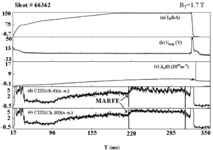
far-FIG. 3: The onset of a MARFE in the HT-7: (a) plasma current, (b) loop voltage, (c) line averaged electron density (vertical chord at r = 0 cm), (d) CIII emission from channel 4, (e) CIII emission from channel 10.
FIG. 4: The H-mode-like plasma: (a) plasma current, (b-e) multichannel Hαemission (Pd7, Pd8, Pd10, Pd12), (f) CIII emission from channel 4, (g) CIII emission from channel 10.
infrared (FIR) hydrogen cyanide (HCN) laser interferome-ter [31-32].The laser source used in the ininterferome-terferomeinterferome-ter was a continuous-wave (CW) DC glow discharge HCN laser with 3.4 m cavity length and 100 mW power output at 337 µm wavelength. The system has a temporal resolution of 0.1 ms with a 10 kHz rotating grating [32].
III. MARFE PHENOMENA AND IMPROVED PARTICLE CONFINEMENT
FIG. 5: Electron density profiles ne(r) by Abel inversion, at t =210 ms (before the event trigger) and t=306 ms (before the end of improved confinement mode).
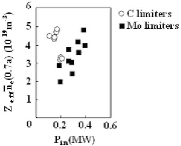
FIG. 6: The critical conditions for the MARFE activity with different limiter materials C and Mo in the HT-7 tokamak.
FIG. 7: MARFE occurs at values ofZe f f1/2fGWin the range of 0.9∼1.2 on new graphite limiters, where fGW = nn¯GWe , (Here ¯neis the maxi-mum line average electron density andnGW is the Greenwald den-sity).
FIG. 8: Comparison of impurity content with graphite and molybde-num limiter materials, in the HT-7 tokamak.
in the plasma edge, which ultimately becomes highly local-ized in tokamaks. Then, as the plasma or impurity density is further increased, the impurities undergo a further transition back into a poloidally uniform band. Since the radiative cool-ing of the edge has been increascool-ing with increascool-ing density, in this final state the plasma is detached or nearly detached.
Figure 3 shows the typical shot of experimental campaign 2004 (shot No.66362) on HT-7 with graphite limiters, the plasma current about 145 kA, the loop voltage Vloop<2−3 V, the toroidal field BT=1.7 T, Ze f f=2.5, R=1.22 m,a=0.27 m, the electron temperature Te=600 eV and the line-averaged density about 5.4x10¹⁹ m−3. A typical position of the MARFE on the HT-7 (shot No.66362) is identified by visi-ble CIII (Channels 4 and 10) line emission as shown in Fig. 3. The MARFE occurs in the plasma column on the inner high field side. The MARFE onset is characterized by a sudden modification of visible CIII (Channels 4 and 10) line emission signal. It is clear that MARFE event occurs from t =215 ms suddenly as shown in Fig. 3.
It must be mentioned that a radiatively improved confine-ment mode, on the HT-7 with molybdenum limiter has been observed [34-35], and the improved confinement mode phase is maintained for about 40 ms. Fig. 4 shows the plasma cur-rent Ip, multichannel Hα emission (Pd7, Pd8, Pd10, Pd12),
CIII emission from channels 4 and 10, in current experiments with graphite limiters on HT-7. It is found that the improved particle confinement phase, which is characterized by multi-channel Hα emission (Pd7, Pd8, Pd10, Pd12) drop and the
line-averaged density increase, is observed clearly from t=225 ms in Fig. 4, exists for about 90 ms and the particle confine-ment timeτPincreased about 1.6 times.
Figure 3 (c) shows the core plasma central electron den-sity increases during onset of improved particle confinement phase, and that if the neutral concentration increases, the MARFE density limit decreases, which were expected from the theory [36] has not measured by direct diagnostics on the HT-7 limiter tokamak.
den-of the line average density, measured at the outermost inter-ferometer channel at r = 20 cm (r/a∼=0.7, the minor radius a = 27∼28 cm), and Ze f f. Under same injected power, the criti-cal density with graphite (C) limiters is much higher than Mo limiter [see Fig. 6].
In the HT-7 tokamak high-Ze f f discharges, it is found that the MARFE occurs at values of Z1e f f/2 fGW = 0.5∼0.7, wherefGW=nnGW¯e , (Here ¯neis the maximum line average elec-tron density andnGW is the Greenwald density), with molyb-denum limiter [8]. The critical factor of MARFE onset is 0.9 ∼1.2 with graphite limiters (see Fig. 7).
However in the HT-7 tokamak the occurrence of a MARFE is not only correlated with the density but also with Ze f f. A quantitative comparison of impurity reduction via density is shown in Fig.8 for Mo and C limiter materials. The main im-purities were reduced in case of graphite limiter. The density limit appeared to be connected with the impurity content [see Fig. 8] and the edge parameters, and the best results,
signifi-particle confinement induced by a MARFE, characterized by Hα line emissions drops and the line-averaged density
in-crease have been studied in the HT-7 ohmic discharges (where the plasma current Ip=145 kA, loop voltage Vloop=2-3 V, toroidal field BT=1.7 T, andZe f f=2-8). It is found that the im-proved particle confinement phase exists for about 90 ms and the particle confinement timeτP increased about 1.6 times. The results are similar to the experiments in TFTR [13], and are consistent with the theoretical explanation [33] given for the TFTR results. The MARFE cools the plasma edge, and the electron density profile is observed to become more nar-row and peaked. In the HT-7, the occurrence of a MARFE is strongly correlated with theZe f f and the wall condition but not with electron density.
Acknowledgements
The authors wish to thank the HT-7 team for cooperation during these experiments.
[1] B. J. Lipschultz, J. Nucl. Mater.145-147, 15 (1987).
[2] N. Hosogane, N. Asakura, H. Kubo, K. Itami, A. Sakasai, J. Nucl. Mater.196-198,750 (1992).
[3] D. R. Baker, R. T. Snider, and M. Nagami, Nucl. Fusion22,807 (1982).
[4] M. Greenwald, J. L. Terry, S. M. Wolfe, S. Ejima, M. G. Bell, S. M. Kaye, and G. H. Neilson, Nucl. Fusion28,2199 (1988). [5] P. C. De Vries, J. Rapp, F. C. Schuller, and M. Z. Tokar, Phys.
Rev. Lett.80,3519 (1998).
[6] T. E. Evans, M.Goniche, A.Grosman, D.Guilhem, W. Hess, and J. C. Vallet, J. Nucl. Mater.196–198,421 (1992).
[7] X. Gao, Y. Jie, C. Xia, M. Wei, Y. Yang, S. Zhang, J. Zhao, L. Hu, Y. Zhu, J. Luo, Y. Zhao, N. Qiu, J. Li, B. Wan, G. Kuang, X. Zhang, X. Liu, X. Gong, Y. Bao, B. Lin, Z. Wu, Y. Li, Y. Shi, M. Song, P. Fu, X. Zhang, M. Zeng, A. Xie, N. Cui, H. Ruan, L. Wang, B. Sheng, S. Liu, W. Ye, K. Yang, J. Liu, Y. Cheng, H. Fan, S. Liu, X. Tong, J. Mao, X. Gu, J. Xie, and Y. Wan, Nucl. Fusion40,1875 (2000).
[8] X. Gao, J. R. Luo, Y. P. Zhao, N. Qiu, Y. X. Jie, Y. Yang, C. Y. Xia, B. N. Wan, G. L. Kuang, X. D. Zhang, J. G. Li, F. X. Yin, X. N. Liu, X. Z. Gong, S. Y. Zhang, J. Y. Zhao, L. Q. Hu, Z. W. Wu, Y. D. Li, K. Yang, Y. Bao, W. W. Ye, L. Chen, H. Y. Fan, S. X. Liu, Y. F. Chen, B. L. Lin, Y. H. Xu, Y. J. Shi, M. Song, X. M. Zhang, M. S. Wei, M. Zeng, A. G. Xie, N. Z. Cui, H. L. Ruan, L. Wang, B. Sheng, S. Liu, X. D. Tong, X. M. Gu, J. S.
Mao, J. K. Xie, and Y. X. Wan, J. Nucl. Mater.279,330 (2000). [9] J. K. Xie, Y. P. Zhao, J. Li, B. N. Wan, X. Z. Gong, J. S. Hu, X. Gao, X. M. Gu, S. D. Zhang, X. M. Wang, Y. Z. Mao, X. K. Yang, M. Zhen, S. Y. Zhang, and HT-7 team, J. Nucl. Mater.
290–293,1155 (2001).
[10] J. Li, Y. P. Zhao, X. M. Gu, C. F. Li, B. N. Wan, X. D. Zhang, J. R. Luo, X. Z. Gong, J. K. Xie, Y. X. Wan, P. J. Qin, X. M. Wang, Y. D. Meng, S. F. Li, X. Gao, Y. Yang, D. Y. Xue, Y. Z. Mao, X. Den, L. Chen, Y. C. Fang, F. X. Yin, S. X. Liu, X. K. Yang, D. Zhen Xu, J. Y. Ding, Y. X. Jie, Q. C. Zhao, J. S. Mao, S. Y. Zhang, J. Y. Zhao, J. S. Hu, H. Y. Fan, M. S. Wei, B. L. Lin, G. X. Wang, Y. D. Fang, and W. C. Shen, Nucl. Fusion39,
973 (1999).
[11] J. Rapp, W. Biel, H. Gerhauser, A. Huber, H. R. Koslowski, M. Lehnen, V. Philipps, A. Pospieszczyk, D. Reiser, U. Samm, G. Sergienko, M. Z. Tokar, and R. Zag´orski, J. Nucl. Mater.290– 293,1148 (2001).
B. Grek, A. Janos, D. W. Johnson, D. Manos, D. K. Mansfield, D. Mueller, H. H. Towner, R. M. Wieland and S. Yoshikawa, J. Nucl. Mater.176–177,792 (1990).
[15] J. D. Strachan, F. P. Boody, C. E. Bush, S. A. Cohen, B. Grek, L. Grisham, F. C. Jobes, D. W. Johnson, D. K. Mansfield, S. S. Medley, W. Morris, H. K. Park, J. F. Schivell, G. Taylor, K. L. Wong, S. Yoshikawa, M. C. Zarnstorff, and S. J. Zweben, J. Nucl. Mater. 145–147,186 (1987).
[16] J. F. Schivell, C. E. Bush, D. K. Mansfield, S. S. Medley, H. K. Park, and F. J. Stauffer, Fusion Technol.15,1520 (1989). [17] F. Alladio, M. L. Apicella, G. Apruzzese, E. Bartiromo, O.
Borra, G. Bracco, G. Buceti, P. Buratti, C. Centioli, M. Ciotti, V. Cocilovo, I. Condrea, F. Crisanti, R. DeAngelis, B. Esposito, C. Ferro, G. Franzoni, D. Frigione, L. Gabellieri, E. Giovannozzi, G. Granucci, M. Grolli, A. Imparato, H. Kroegler, M. Leigheb, L. Lovisetto, G. Maddaluno, G. Mazzitelli, P. Micozzi, A. Mo-leti, F. Orsitto, L. Panaccione, D. Pacella, M. Panella, V. Peri-coli, L. Pieroni, S. Podda, G. B. Righetti, F. Romanelli, S. E. Segre, E. Sternini, A. A. Tuccillo, O. Tudisco, F. Valente, V. Vitale, R. Zagorski, V. Zanza, and M. Zerbini, Plasma Phys. Control. Fusion36,B253 (1994).
[18] M. Lipa, P. Chappuis, and P. Deschamps, Fusion Technol.19,
2041 (1991).
[19] G. L. Jackson, D. R. Baker, K. L. Holtrop, S. Konoshima, R. Maingi, G. M. Staebler, and W. P. West, J. Nucl. Mater. 220-222,173 (1995).
[20] X. Gao, Y. X. Jie, Y. Yang, C. Y. Xia, M. S. Wei, S. Y. Zhang, Y. F. Cheng, L. Q. Hu, J. S. Mao, X. D. Tong, B. N. Wan, G. L. Kuang, J. G. Li, Y. P. Zhao, J. R. Luo, N. Qiu, K. Yang, G. Li, J. K. Xie, and Y. X. Wan, Phys. Plasmas7,2933 (2000). [21] X. Gao, J. Li, Y. Yang, J. K. Xie, J. R. Luo, J. Y. Zhao, X. Z.
Gong, L. Q. Hu, X. D. Zhang, Y. J. Shi, B. N. Wan, K. Tanaka, R. Sakamoto, Y. P. Zhao, G. L. Kuang , J. S. Hu, M. Asif, Y. X. Jie, H. Q. Liu, J. Liu, Q. Xu, L. Gao, and the HT-7 Team, J. Nucl. Mater.337–339,835 (2005).
A.342,175 (2005).
[25] M. Asif, X. Gao and HT-7 Team, Phys. Lett. A. 346, 305 (2005).
[26] M. Asif, X. Gao and HT-7 Team, Phys. Lett. A. 349, 250 (2006).
[27] Y. Yang, Y. Bao, J. Li, X. Gu and Y. He, Nucl. Fusion39,1871 (1999).
[28] X. Gao and HT-7 Team, Plasma Sci. Technol.1,25 (1999). [29] G. Kuang, Y. Liu, J. Shan, W. Xu, X. Zhang, D. Liu, F. Liu,
Y. Zhu, C. Zhang, G. Zheng, J. Wu, J. Lin, B. Ding, H. Xu, Y. Fang, J. Li, J. Luo, X. Zhang, B. Wan, Q. Zhao, J. Mao, X. Gao, S. Zhang, C. Li, X. Gu, P. Qing, H. Fan, S. Liu, B. Ling, B. Ding, Y. Li, Z. Wu, Y. Jie, S. Liu, J. Xie, and Y. Wan, Nucl. Fusion39,1769 (1999).
[30] Y. P. Zhao J. Li, J. K. Xie, Y. D. Meng, X. C. Wu, Y. X. He, D. Y. Xue, X. Deng, and Y. G. Shao, Chin. Phys. Lett.14,916 (1997).
[31] X. Gao, H. J. Lu, Q. L. Guo, Y. X. Wan, and X. D. Tong, Rev. Sci. Instrum.66,139 (1995).
[32] Y. X. Jie, X. Gao, Y. F. Cheng, K. Yang, and X. D. Tong, Int. J. Infrared Millimeter Waves21,1375 (2000).
[33] W. M. Stacey, Phys. Plasmas3,2673 (1996).
[34] X. Gao, Y. P. Zhao, J. R. Luo, Y. X. Jie, X. Z. Gong, B. N. Wan, J. G. Li, F. X. Yin, G. L. Kuang, X. D. Zhang, S. Y. Zhang, N. Qiu, X. N. Liu, J. Y. Zhao, Y. Yang, Y. Bao, B. L. Lin, Z. W. Wu, Y. D. Li, Y. H. Xu, K. Yang, G. X. Wang, W. W. Ye, L. Chen, Y. J. Shi, M. Song, X. M. Zhang, P. J. Qin, X. M. Gu, N. Z. Cui, H. Y. Fan, S. X. Liu, Y. F. Chen, L. Q. Hu, J. S. Hu, C. Y. Xia, H. L. Ruan, X. D. Tong, J. S. Mao, J. K. Xie, and Y. X. Wan, Plasma Phys. Control. Fusion41,1349 (1999).