ABSTRACT: This paper presents the application of the Design for Manufacture and Assembly method (DFMA) during the conception of a space product. This approach enables to capture manufacture and assembly requirements in early phases of development. DFMA guides the manufacture processes and materials that rule the Fins Module interface to the Microsatellite Launch Vehicle (VLM-1) main structure. The results of this process are the requirements captured in the beginning of the project development, allowing avoiding problems that generally occur in the manufacture stage and in assembly, integration and test (AIT) phase. Rework, material loss, wasting time to assembly and integration, over engineering and unnecessary engineering are problems that the method intends to reduce in the physical implementation phase.
KEYWORDS: Design for manufacture, Design for assembly, Concurrent engineering.
Fins Module Conception of the Microsatellite
Launch Vehicle Based on Design for
Manufacture and Assembly Method
Jéssica Garcia de Azevedo1, Artur Cristiano Arantes Filho1, Luis Eduardo Vergueiro Loures da Costa1
INTRODUCTION
he Microsatellite Launch Vehicle (VLM-1) is a project under development at Instituto de Aeronáutica e Espaço (IAE) in Brazil and aims at carrying small satellites and small payloads to space. Its development was stated as a cost-driven process which involves the important aspects in anticipation of the requirements to the initial stages of the development (Fulindi, 2011). he VLM-1 is a three-stage solid propelled rocket, which provides the necessary energy to reach low equatorial orbits. his project is developed in cooperation with the National Aeronautics and Space Research Centre of the Federal Republic of Germany (DLR), and the irst light of the VLM-1 will be able to put in low orbit the German payload called Shefex III.
In space projects, diferent ields of research and engineering, as materials, mechanics, electronics, control and others, are involved. In each conception model of the project, analyses of the functional aspects, with materials to be adopted, mechanical stresses, equipment assembly and preliminary actions are taken in order to integrate such a multifunctional group. his group aims at performing the integrated product team. From the Design for Manufacture and Assembly method (DFMA) analysis, more eicient actions are taken to anticipate requirements for the beginning of the product development. his leads to reduced problems in the assembly, better ideas to prepare the manufacture process, and the decision on materials is taken in the same time when the process is under analysis. Furthermore, all impacts are analyzed in the conception stage of the project. In this work, DFMA is applied aiming at developing the VLM-1 Fins Module.
1.Instituto de Aeronáutica e Espaço – São José dos Campos/SP – Brazil.
Author for correspondence: Artur Cristiano Arantes Filho | Instituto de Aeronáutica e Espaço | Praça Marechal Eduardo Gomes, 50 – Vila das Acácias CEP: 12.220-098 – São José dos Campos/SP – Brazil | E-mail: [email protected]
Based on DFMA arising from Concurrent Engineering methodology, it was possible to achieve a balanced solution for the VLM-1 Fins Module, which considered organizational aspects, manufacture techniques and assembly strategies. As the main result, one can outstand a Fins Module conceptual design, considering real needs from stakeholders and adapted for the Brazilian technological scenario.
PRODUCT DEVELOPMENT PROCESS AND CONCURRENT ENGINEERING
Product Development Process (PDP) consists of applying a set of activities aiming at reaching the design speciications and its production process. So that, manufacture is able to produce it, from the needs of the market, possibilities and technological constraints, considering the competitive and company’s product strategy.
On the other side, as stated by Huang (1996), Concurrent Engineering (CE) improves quality, reduces costs, compresses cycle times, increases lexibility, raises productivity and eiciency, and improves the social image, making an ideal environment for product development.
he practice of CE has applied methodologies during the product development aiming at integrating engineering tools in order to help in decision-making, such as Design for X (DFX), DFMA (Design for Manufacture and Assembly), Computer Aided Design (CAD), Computer Aided Engineering (CAE), Computer Aided Manufacturing (CAM), among others.
Design for X
DFX is one of the most efective approaches to implement CE. he called X can be quality, manufacture, assembly, cost, among other features related to the product life cycle process (Huang, 1996).
DFX has become a powerful tool for project analysis of products, promoting the practice of CE in a prediction error process of subsequent processes. In other words, DFX assists in raising the largest number of project related information, in view of facilitating decisions in the preliminary stages, which generally have less information than in future phases. Since the 1960s, eforts have been made in the study of conceptual and detailed design of products, aiming at manufacture and assembly analysis. Among the various methodologies that compose the DFX, there are some that are already being more strongly applied, having a wider literature and well-structured implementation methods, such as Design for Manufacture and Design for Assembly methodology (Iwaya, 2010).
Design for Manufacture
In Design for Manufacture, or DFM, the product is developed for production, aiming at facilitating and reducing the production cost.
According to Xie (2003), DFM is the method that considers the limitations related to manufacture in the initial phase of the project. hus, the project engineer can make the selection between diferent materials and technologies in order to estimate the manufacture time and the product cost quantitatively and to quickly choose between diferent project plans. he project team compares all types of project plans and technology, and revisions are carried out in the initial phase of the project according to the feedback information. Therefore, the most satisfactory coniguration for the product can be determined. here are three objectives in DFM:
• Improving the quality of new products during the development period, including project, technology, manufacture, service and so on.
• Decreasing the cost, including the design cost, technology, manufacture, delivery, technical support, disposal, and so on.
• Shortening the development cycle, including project time, preparation for manufacture, and calculation of repeatability.
Currently, DFM is widely applied with CAD/CAM systems, where the designer can extract the features of a modeled part in order to predict spending and determine manufacture processes. his allows project modiications for the choice of the best product engineering solutions.
Design for Assembly
As stated by Redford (1983), through Design for Assembly (DFA) application in a development early phase, a signiicantly cost reduction can be achieved during the inal integration and assembly stage. he mentioned cost reduction could be attained accomplishing the project of parts that can be easily handled and products that can be easily assembled manually or by machine. In general, improvements can be typically achieved through DFA implementation, resulting in cost reduction. This fact occurs because there are not ideal attention in assembly strategies and time spending to execute this step of development.
Figure 1. Framework for project of ins module.
Top-down approach
PDP DFM DFA DFMA
CAD/CAE Objectives tree Morphological chart
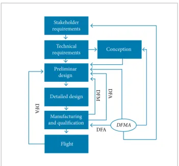
Figure 2. Project lowchart of Design for Manufacture and Assembly method.
D
FA
D
FA
DF
M
DFA DFMA
Conception Stakeholder
requirements
Preliminar design
Detailed design
Flight Manufacturing and qualification
Technical requirements • During the operation of the product, the part moves
in relation to all other parts already assembled? Only overall motion should be considered — small movements that can be accommodated by integral elastic elements, for example, are not suicient for a positive response. • he part must be of a diferent material or be isolated
from other parts already assembled? Only fundamental reasons related to the material properties are acceptable. • A piece must be separated from all other parts already assembled because, otherwise, required assembly or disassembly of other separate parts would be impossible.
Design for Manufacture and Assembly
Huang (1996) deines a better alternative in a project by the optimization of the manufacture and assembly process, applying DFMA approach. his approach is a systematic analysis used in the preliminary phases or in the project review, when problems of product manufacture and assembly appear and when a product is losing its market.
his approach is the basis for CE studies, providing guidance to the design team, simplifying the product manufacture and assembly, reducing costs — as a benchmarking tool that aims at studying competitors — and quantifying manufacture and assembly diiculties, as a should-cost tool, helping negotiate suppliers’ contracts.
As stated by Boothroyd et al. (1994), “to manufacture” refers to the manufacture of the individual component parts of a product or assembly and “to assemble” refers to the addition or joining of parts to form the completed product. Assembly will not be considered a manufacture process in the same sense that machining, molding etc., which are manufacture processes. Hence, the term Design for Assembly (or DFA) means the design for ease of assembly. hus, Design for Manufacture and Assembly (DFMA) is a combination of DFA and DFM.
The DFMA concerns to anticipate the assembly and integration requirements for the development phase, reducing future problems in the project physical implementation.
METHODOLOGY
he methodology applied in this work is based on references, tools and approaches used in the VLM-1 Project. It is characterized as a qualitative research, according to Silva and Menezes (2001); the interpretation of the phenomena and the attribution of the
meanings are basics in the qualitative research process. It does not require the use of methods and statistical techniques. he process and its meaning are the principal focus of the approach.
In order to collect and understand the methods and tools, a line of reasoning considering a framework for the execution of the project can be built, where they are used, starting from the highest to the lowest level. As a result, one has a broader approach as it reaches the inal objective (Fig. 1). his approach aims at involving development scenarios to obtain the best design solution.
From the stakeholders’ requirements, the technical requirements that will feed the product conception are deined. he preliminary design is developed based on the requirements anticipation of the manufacture and qualiication phase through the DFA and DFM analysis tools, in which the physical elements that will compose the inal assembly can be identiied as well as how they will be performed. For the processes used in manufacture, materials and types of tools for the visualization and analysis of these elements are used, with CAD and CAE sotware to validate the concepts generated from the requirements. In this phase, the requirements to the module integration in the vehicle main structure and to aid the launch pad are identiied. his analysis looks to the type of the module ixation with the bottom vehicle in the launch pad. In the same time, the question “how to integrate?” the equipment distributed in the vehicle and distributed in the integration tower is analyzed. hough DFA analysis, it is possible to detail and planning all the integration process of the vehicle to the light phase.
For the VLM-1 Project, a cluster of four ins coupled to a cylindrical membrane structure is required, denominated here Fins Module. he types of manufacture studied attending the project are: carbon, aluminum, iberglass, and sandwich type in core and aluminum, or core and foam.
The Fins Module also integrates the fins in the vehicle body and aids to protect the equipment inside of the vehicle. Knowing the mechanical and aerodynamics characteristics of the VLM-1, as static margin, the main functions and objectives are identiied. hese objectives are organized and deployed as an objective tree, which drives to the goals and the metrics that
determine the guidelines to the project’s physical implementation (Palmerio, 2008).
As stated by Summers (2000), objective trees are used to model the hierarchical nature of the requirements, or objectives, of a design problem. his tool has been used for problem deinition and clariication in the early stages of design, though it should be reviewed to ensure that design team is kept on task. Questions about how to measure as well its impact and importance in the design development must be raised, if the objective was achieved. he irst question will derive metrics (it means a word as cost, schedule, fuel economy, productivity that encompasses a set of measures). he metrics are deployed to the measures (objectives and quantiiable). Cross (2008) stated that in order to identify the product objectives, the questions “why?”, “how?” and “what?” are used to expand and clarify the objectives. Aterwards, the objectives are hierarchically drawn in the tree diagram. In this way, the importance of each objective is analyzed aiming at establishing which one should be achieved irst.
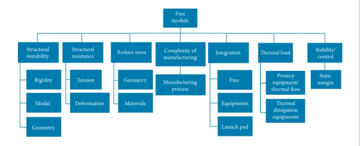
Figure 3 shows the objective tree for the VLM Fins Module. he main objectives are deployed towards the lower levels. From these objectives the functions will be attained.
When the objectives unfold, one can identify the features that have become the principal functions of the Fins Module. hese functions were represented by physical elements, which, through a morphological chart, allowed building the first physical conceptions.
According to Cross (2008), the morphological chart method exploits all possibilities of combination and encourages the designer to identify novel combinations of elements
Figure 3. Objective tree of ins module.
Structural instability
Structural
resistance Reduce mass
Materials
Integration
Fins
hermal load Stability/
control
Static margin
Equipments
Launch pad
hermal dissipation equipments Protecy equipment/ thermal flow
Deformation Tension Rigidity
Modal
Geometry
Geometry
Fins module
Complexity of manufacturing
or components. he chart sets out the complete range of elements, components or sub-solutions that can be combined together to make a solution. he number of possible combinations is usually very high, and includes not only existing conventional solutions but also a wide range of variations and completely novel solutions.
By analyzing the Fins Module objective tree, the following characteristic were raised: being rigid, resistant, and light, reducing manufacture complexity, enabling integration, allowing thermal dissipation and the vehicle’s controllability. he physical elements that meet the Fins Module are known and their dimensions are deined by relevant calculations to other studies.
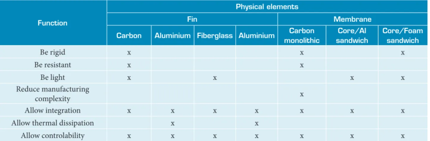
Table 1 shows the Fins Module Morphological Chart, which can permit a comparison between diferent solutions for the same requirements arising from the objective tree. he conception deined is about carbon ins and also carbon monolithic membrane based on the principal functions for the system, as mass, stifness and structural strength.
The carbon was chosen based on the fins material characteristics. Carbon fins are more rigid and resistant, which is one of the most important requirements of the Fins Module. he low carbon density compared to aluminum and the glass iber make the ins lighter and, as result, it implements the mass reduction requirement. he rigidity and resistance characteristics impacted in the choice of the carbon monolithic membrane. When compared to other materials, it is more adequate for the manufacture, where the performed process reduce the manufacture time.
The choice of the best solution is made based on the manufacture procedures of the module, as well as the integration in the vehicle, taking into consideration the three more relevant
Function
Physical elements
Fin Membrane
Carbon Aluminium Fiberglass Aluminium Carbon monolithic
Core/Al sandwich
Core/Foam sandwich
Be rigid x x x
Be resistant x x
Be light x x x x
Reduce manufacturing
complexity x
Allow integration x x x x x x x
Allow thermal dissipation x x
Allow controlability x x x x x x x
Table 1. Morphological chart of ins module.
Assembly, integration
and test (AIT)
Product operation Development
organization
People → IAE/DLR Diverse resources Aerodynamics
Figure 4. Scenarios from the life cycle process.
scenarios to the system (Fig. 4), chosen from several ones. An analysis with all deployment of the possible scenarios from the life cycle processes is not represented in this work. he scenarios are environments that involve the process of life cycle of the product. In other words, each scenario presents the project elements needed for the development, which are related to the system when subjected to DFMA analysis.
identiied. All these parameters inluence in the aerodynamics and the vehicle’s trajectory.
RESULTS
Based on the analysis of the main functions raised and the obtained results using the applied tools, it was possible to describe the first manufacture and assembly for the Fins Module. It is worth to highlight that the number of integration hours and mass limit value for the module derived from calculations belong to other stages of Project VLM-1 development.
he following list presents the irst requirements of the Fins Module:
• The Fins Module shall permit the integration of the launch pad.
• he Fins Module shall have mechanical interface to the ins.
• he Fins Module shall have vehicle electrical interface with the launching tower.
• he Fins Module shall be integrated in 3 hours. • he Fins Module shall have a mass less than 90 kg. • he Fins Module shall have at most 10 elements for
integration.
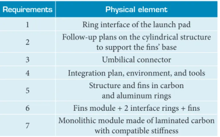
• he Fins Module shall not allow structural instability. Table 2 describes each requirement that was allocated for each physical element deined for analysis and studies. Figures 5 and 6 present the irst CAD conception of these elements.
Figure 7 shows the physical dimensions of the Fins Module, in a sectional view. hese dimensions match with the requirements stated for this part of the vehicle.
Requirements Physical element
1 Ring interface of the launch pad
2 Follow-up plans on the cylindrical structure to support the ins’ base
3 Umbilical connector
4 Integration plan, environment, and tools
5 Structure and ins in carbon and aluminum rings 6 Fins module + 2 interface rings + ins
7 Monolithic module made of laminated carbon with compatible stifness
Table 2. Allocation of the requirements.
Launch pad interface ring
Monolithic structure Umbilical conector Motorpropulsor S50
interface ring
Fins
1,460 mm
5 mm thick
690 mm 628 mm
4 flat surface with width of 100 mm Figure 5. First conception of ins module in CAD.
Figure 6. Explode view of ins module in CAD.
Figure 7. Physical dimensions of ins module.
Volume 3.3557712e-07 mm3
Surface area 1.3335811e+07 mm2
Average density 2.3960170e-04 kg/mm3
Mass 8.0404848e+03 kg
Center of gravity: X 0.0000000e+00 mm
Center of gravity: Y 1.5783229e+00 mm
Center of gravity: Z 8.7176133e+02 mm
Inertia tensor: Izx 0.0000000e+00 kg x mm2
Inertia tensor: Izy 0.0000000e+00 kg x mm2
Inertia tensor: Izz 2.0991524e+07 kg x mm2
Table 3. Results of the ins module model analysis.
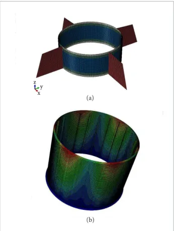
Figure 8. Structural analysis in CAE software with ins (a), and with isolated structure (b).
A structural CAE static analysis and modal analysis showed that results reached the main objectives proposed, approving the Fins Module conception for use in light conditions expected for the VLM-1, without problems related to buckling efects and lutter, decoupling frequencies on the ins. Figure 8a shows the inite element method for structural response of the Fins Module, equipped with four ins; on the other side, one notices in Fig. 8b an example of membrane structure subjected to compression load. herefore, it is concluded that there is a load distribution, which makes the module comply with the requirements of rigidity and resistance.
According to the Fins Module’s physical and structural characteristics, and the adopted materials, a manufacture requirements proposal for the Fins Module was raised, following the guidelines of a DFM analysis:
• Manufacture process of carbon structure: type ilament winding (winding process of continuous ibers on a rotating mandrel in predetermined pattern). • Manufacture process of the rings: machining of
aluminum plate.
he type ilament winding process reduces direct labor in lamination and, consequently, there is a cost reduction of the product. he machining of the rings will follow the proiles drawn in CAD, respecting the DFM guidelines for machining process. From the conception generated in CAD and their characteristics, it is presented a proposal of components integration of the Fins Module. his was carried out following the guidelines of a DFA analysis, as well as it was taken into account handling the module during transport and integration.
he logical order of the sequence of events was respected: • Assembly of the rings in the module structure before
the launch site transportation.
• Transport of the rings integrated to the module structure with security and protection against impacts. • Transport of the ins separately to the structure with
security and protection against impacts.
• Integration of the hrust Vector Assembly (TVA) module to the irst stage motor case in the horizontal position. • Integration of the ins to the module structure in the
horizontal position.
• Integration of the irst stage to the launch pad by the launch pad interface ring.
• Integration of the other modules and stages of the vehicle. • Integration of the electrical interfaces between the
vehicle and the launch pad through the umbilical connector modules present in the vehicle.
From the mentioned integration sequence, it is possible to deploy the Vehicle Integration Plan. In this plan, all steps are detailed, respecting all safety and time requirements. In this work, it will not be showed due to the complexity of the plan and the publishing restrictions. he product conception is carried out simultaneously with the development process
z y x
(a)
in the preliminary phase of the project, considering all the requirements identified using DFMA analysis. Then, the physical implementation of the product was done, with all needed attributes aiming at avoiding rework in future phases of project. his optimizes the time and cost of the manufacture and integration phases.
CONCLUSIONS
he design for manufacture and assembly analysis was presented to the VLM-1 Fins Module conception. A CAD model was developed from the study of the methodology and application of the tools. he DFMA analysis derived the requirements to the physical implementation. From these requirements and the knowledge gained using the DFMA analysis, it was possible to take into account the anticipation of the elements that impact generally in the manufacture, assembly and test phases. his guides to avoid material loss, rework, wasting time to assembly and integration, over engineering and unnecessary engineering throughout the life cycle process.
hus, describing a framework propose, created from the methodologies analyzed and deinitions from VLM-1 project, it
was possible to apply the concepts of the DFMA method aiming at deining the characteristics of the Fins Module.
he presented results emerged due to the implemented application, when the guidelines were used aiming at the conception of a CAD model and the survey of the irst DFM and DFA requirements for the Fins Module.
Also falls the importance of applying DFMA method throughout the VLM-1 project, as in the case of a low-cost project, where new technologies are approached and used; this method helps in raising the requirements for manufacture and integration present in the development phases in order to minimize the possible errors that may occur in implementation and vehicle’s light.
PROPOSALS FOR FUTURE WORKS
As this work is a part of the current studies on the development of the VLM-1 project, it will serve as the principle for the next related studies, using the presented methods for the development of other subsystems conceptions of the vehicle.
Based on the framework presentation for the product development, this work can be used as a basis for studies of other product development methods as well.
REFERENCES
Boothroyd, G., Dewhrust, P. and Knight, W., 1994, “Product Design for Manufacture and Assembly”, Marcel Dekker, Inc., New York.
Cross, N., 2008, “Engineering Design Methods: Strategies for Product Design”, Fourth Ed., Wiley, Hoboken, USA,, 230p.
Fulindi, J.B., 2011, “Auxílio Computacional a um Processo de Engenharia Simultânea de Sistemas Espaciais”, Instituto Nacional de Pesquisas Espaciais, São José dos Campos, Brazil.
Huang, G.H., 1996, “Design for X: Concurrent Engineering Imperatives”, Chapman & Hall, London, UK, 489p.
Iwaya, L.H., 2010, “Estudo sobre a Evolução do DFX”, Retrieved in May 20, 2013, from http://leansolutions.com.br/index.php?option=com_ phocadownload&view=category&id=1:artigos&Itemid=127
Palmerio, A.F., 2008, “Introdução à Tecnologia de Foguetes”, Seventh Ed.
Redford, A.H., 1983, “Design for Assembly”, Department of Aeronautical and Mechanical Engineering. University of Salford, UK. Vol 4. No 3.
Silva, E.L. and Menezes, E.M., 2001, “Metodologia da Pesquisa e Elaboração de Dissertação”, Third Ed., Laboratório de Ensino a Distância da Universidade Federal de Santa Catarina, Florianópolis, Brazil.
Summers, J.D., 2000, “Design Tool – Objective Tree”, Mechanical Engineering Department. Clemson University. Retrieved in January 15, 2015, from http://www.clemson.edu/ces/cedar/ images/1/19/05-ObjectiveTree.pdf