Abstract— In this paper, a novel design of a compact planar ultra wide band (UWB) monopole antenna with triple band notched characteristics has been presented. The antenna has a unique shape and has been fed through a 50 Ω microstrip feedline. The strength of the antenna lies in three band notched properties for WiMax system at 3.3 - 3.7 GHz, WLAN IEEE 802.11a at 5.15 - 5.85 GHz and X band satellite communication at 7.25 - 8.395 GHz. The notched bands have been achieved by incorporating an inverted U-slot etched on the radiator patch, an inverted C-U-slot also on the radiator patch and a U-slot on the microstrip feed line. In order to achieve FCC defined impedance bandwidth of 7.5 GHz, a rectangular cut in the ground plane has been introduced along with staircase structure in the bottom edge of the radiator. The proposed antenna is having a compact size of 30 X 30 X 1.6 mm3 and exhibits a large bandwidth from 2.8 GHz to 10.7 GHz. The antenna has been successfully simulated and fabricated. The radiation pattern is omni-directional in H-plane and the E-plane exhibits dipole like radiation pattern. The gain of the antenna is stable across the whole operating frequency band except at three notched bands.
Index Terms— Ultra-wideband (UWB), Triple band-notched antenna, planar UWB antenna, slotted ground plane, C-shaped slot, U-shaped slot, WLAN, WiMax.
I. INTRODUCTION
Over the last few years, UWB technology has emerged as one of the most attractive options for
short range communication coupled with high rate of data transmission at very low energy level
utilizing pulse based communication. Since the time Federal Communication Commission (FCC) in
Mar 2002 approved [1] the release of -10 dB unlicensed bandwidth of 7.5 GHz ranging from 3.1 -
10.6 GHz with effective isotopic radiated power (EIRP) spectral density of -41.3 dBm/MHz, intense
research activities have been reported both from academia and industry with a view to exploit its full
potential. The most important component in UWB based applications is the antenna which needs to be
compact, low profile, simple in structure and offering ease of integration with devices having small
physical size. The antenna is also required to have good omni-directional properties and stable gain
throughout the operating bandwidth.
The main challenge in designing an UWB antenna for indoor communication system is the
avoidance of interference with existing narrowband services which may cause potential interference,
Design of a Triple Band-notched UWB Planar
Monopole Antenna
Sanjiv Tomar, Ajay Kumarfor instance, WiMax (wireless interoperatibility for microwave access) for some Asian and European
countries operating at 3.3 - 3.7 GHz, WLAN (wireless local area network) IEEE 802.11a operating at
5.15 - 5.85 GHz and X band satellite communication operating at 7.25 GHz - 8.395 GHz. It is thus
essential to design an antenna which is not only compact and planar but also has multiband filtering
capability to protect the UWB based applications from possible interference from existing narrow
band services. While integrating a bandstop filter with UWB antenna may increase the complexity
and cost of fabrication [2], however, antenna design incorporating band notched characteristics is a
simpler way to solve the interference problem.A number of designs have been reported till now for
multi band notched functions with in-built structures or design topology to avoid EM interference.
Broadly, various techniques of band rejection capability involves etching slots of various shapes and
sizes on radiating patch, microstrip lines or ground plane [3]-[11], embedding stubs in the radiator
patch or in the vicinity of feedline [12]-[14], use of metamaterial [15]-[17] or electromagnetic band
gap structure [18]-[20]. Using these techniques, a number of antenna designs have been reported in
which single band notch [21]-[22] , dual band notch [23]-[24], triple band notch [25]-[26] and
quadruple band notch [27] have been reported the most. It is observed that in most of the reported
designs the antenna size is relatively large and the notched bands are quite wide thereby resulting in
reduction in useable bandwidth for UWB communication. Moreover, the mutual coupling among each
slot or each parasitic strip leads to a more complicated design procedure requiring tedious simulations
and long simulation time to achieve design goals [28].
In this paper, a compact printed unique lamp post shaped UWB monopole antenna having triple
band notched characteristics has been proposed. The notched bands have been achieved by etching a
U-slot and a C-slot on the radiator patch and a U-slot on the microstrip feedline. In order to achieve
wideband matching of the transmission with the radiator, a rectangular cut has been introduced in the
partial ground plane just below the feedline. The stepped structure at the lower edge of the radiator
also results in improvement in the characteristics of the high frequency band.
The band notched functions of the antenna has been achieved by etching three slots at different
locations. The length of the slots is taken to be one half of the guided wavelength at the respective
notched band frequency [29]. The length of each slot can be calculated using the expression (1) and
(2) as under:
(1)
where, (2)
While, fnotch is the centre frequency of the notch band, Lslot is the length of the slot, εeff is the
effective dielectric constant and c is the velocity of light. The dimension and position of each slot can
be altered independently in order to achieve control over the notched bands. The design of the antenna
has been simulated and optimized using CST Microwave Studio Suite TMand successfully fabricated.
The proposed antenna exhibits dipole like radiation pattern in the E-plane and omnidirectional
radiation pattern in H-plane for the entire frequency range of 3.1 to 10.6 GHz.
II. ANTENNADESIGNANDANALYSIS
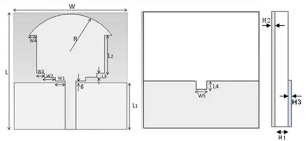
The geometry of the proposed initial antenna is shown in Figs. 1 (a), (b), and (c). The antenna has a
compact geometry of 30 x 30 mm2. It has been printed on FR4 substrate of thickness 1.6 mm having
loss tangent of 0.02. The radiator is fed through a 50Ω microstrip line. The partial rectangular ground
plane having a rectangular cut just beneath the microstrip feedline has been printed on the other side
of the FR4 substrate. A gap ‘g’ has been introduced between the lower edge of the radiator patch and
upper edge of the ground plane to achieve wide impedance bandwidth. The stepped structure at the
bottom of the radiator has been incorporated for improved characteristics of high frequency band. The
optimal antenna dimensions after optimization are shown in Table 1.
(a)
(b)
Fig. 1. The design geometry of proposed initial planar monopole UWB antenna. (a) Front view (b) Back view. (c) Side view.
TABLE 1. DIMENSIONS OF VARIOUS PARAMETERS OF PROPOSED INITIAL MONOPOLE UWB ANTENNA.
Parameter
W
L
R
W
1W
2W
3W
4W
5Size (mm)
30
30
11
2.6
3
2
2
2
Parameter
L
1L
2L
3L
4g
H
1H
2H
3Fig. 2 shows the simulated VSWR of primitive antenna without any slot. The simulated response
indicates a wide impedance bandwidth from 2.45 GHz to more than 12 GHz for VSWR<2.The wide impedance bandwidth can be attributed to optimized value of gap ‘g’ between the radiator and the ground plane.
Fig. 2. VSWR of initial compact planar monopole UWB antenna without slots.
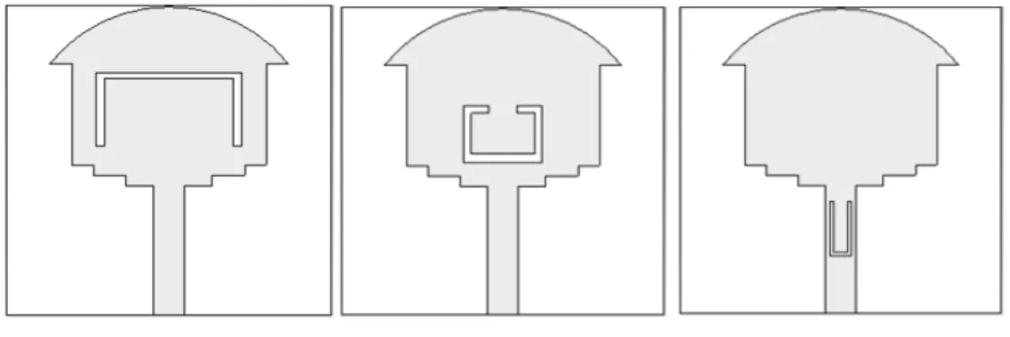
Antenna a Antenna b Antenna c Fig. 3. Geometry of compact planar monopole UWB antenna having individual slots.
Fig. 3 shows the evolution of design of proposed UWB antenna from initial antenna. The slots for
band notched characteristics are introduced individually and analyzed in terms of VSWR for each
slot. The antennas labeled as a, b and c have been designed to notch frequency bands centered at 3.5,
5.5 and 7.8 GHz. The simulated VSWR of antenna having individual slots is shown in Fig. 4. The
location of the center frequency of the notched band is determined using (1) i.e. length of each slot. It
is noted that antennas a, b and c are able to notch frequency bands individually centered at 3.5 GHz,
5.5 GHz and 7.8 GHz, respectively. The location of each slot is different on the radiator thus they do
Fig. 4. VSWR of individual antenna having single notch.
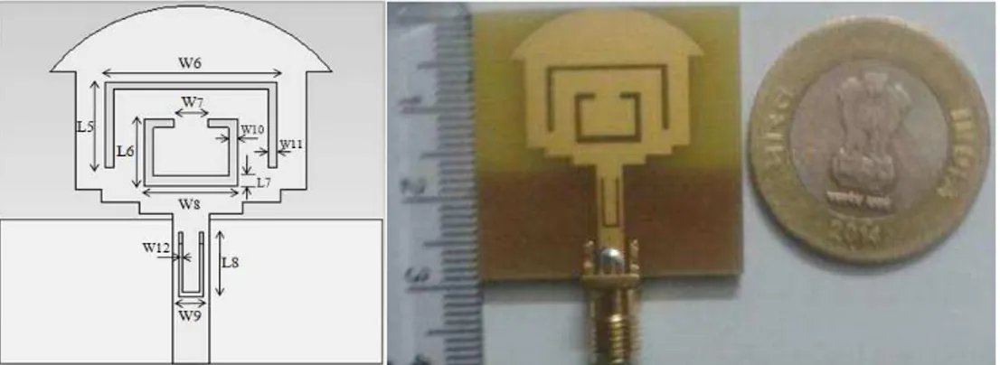
A. Compact Planar Monopole UWB Antenna with Triple Band Notched Characteristics
After having simulated the individual band notched function, the three slots are then incorporated in a
single antenna. The geometry of the compact antenna having triple band notched function and the
photo of fabricated antenna has been shown in Fig. 5 (a) and (b). The three stop bands have been
generated by using an inverted U-slot in the radiator, a U-slot in the microstrip feedline and a C-slot in
the radiator. The extent to which each slot is able to notch the frequency band depends upon the
length, width and gap of the slot. The dimensions of the compact antenna having triple band notched
function after optimization is as follows: W6 = 13.5 mm, W7 = 2.7 mm, W8 = 7.3 mm, W9 = 2 mm,
W10 = 0.6 mm, W11 = 0.75 mm, W12 = 0.35 mm, L5 = 7, L6 = 5.5mm, L7 = 0.85, and L8 = 5.4 mm.
B. Results and Discussion
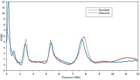
The final design of the compact planar monopole antenna as shown in Fig. 5 was fabricated and
measurements carried out using Agilent PNA-L N5231A Network Analyzer. Fig. 6 shows the
simulated and measured VSWR curve of the fabricated antenna. The measured impedance bandwidth
of the proposed antenna is 2.8 - 10.7 GHz for VSWR<2 with three stop bands centered at 3.5, 5.5 and
7.8 GHz. As a result the antenna is able to avoid interference with narrowband services of WiMax,
WLAN and also X band satellite communication. The bandwidth of each slot can be independently
adjusted by changing the length and location of the corresponding slot. The measured results are in
good agreement with the simulated ones with very little variation. The variation in measured and
simulated response is primarily due to fabrication errors, soldering of SMA connector or the ambient
environment in which the measurements are carried out.
Fig. 6. Simulated and measured VSWR of proposed compact monopole UWB antenna.
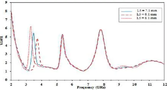
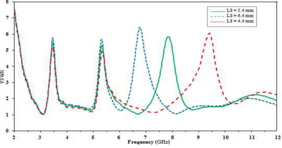
In order to analyze the mutual coupling of the slots, parametric analysis is carried out by changing
one parameter at a time and keeping the other parameters fixed. For simplicity, only the parameter L5,
L6 and L8 are studied and simulation carried out. As shown in Figs. 7, 8, and 9, the first, second and
third notched band shifts to lower frequencies as the slot length is increased while decrease in overall
length shifts the center frequency to higher frequency. It is seen that the variation in the physical
length of one slot leading to shift in the center frequency of the notched band does not affect the other
notched bands. It is due to the fact that the etched slots are located at different locations and coupling
between them is quite weak. It can therefore be inferred that the notched bands can be controlled individually by controlling the dimension and location of the slots. Dimension of gap ‘g’ is also changed to study its effect on VSWR. As shown in Fig. 10 on increasing the dimension of gap‘g’
between lower edge of radiator patch and upper edge of ground plane, the notched bands centered at
frequency to higher ones. The change in dimension of gap g has no effect on higher notched band
centered at 7.8 GHz.
Fig. 7. Optimization of slot S1 for first notched band.
Fig. 9. Optimization of slot S3 for third notched band.
Fig. 10. Optimization of gap ‘g’ for FCC defined bandwidth.
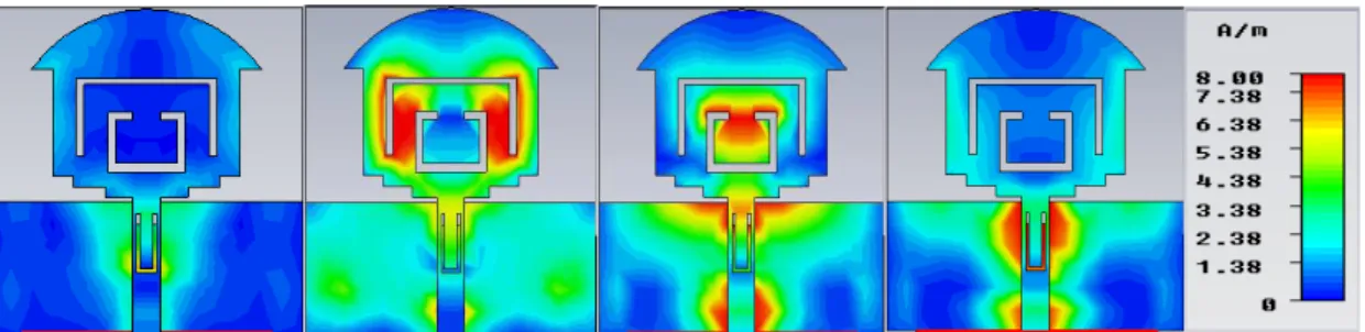
Further analysis of the band notched characteristics is carried out by analyzing the surface current
distribution at pass band and stop band frequencies. The simulated current distribution at pass band
frequency of 6.5 GHz is shown in Fig. 11. It is seen that the current is evenly distributed at the
radiator surface therefore, the three slots have negligible effect at pass band frequency. However, at
notched frequency of 3.5, 5.5 and 7.8 GHz, the three slots have considerable current concentration
around the slots which acts as resonators. The current in radiator patch is quite small and hence, it
does not radiate. At the same time, the ground plane has large surface current flowing through it
impedance mismatch thereby leading to increase in return loss at respective notched band and
decrease in radiation efficiency and gain of antenna.
Fig. 11. Simulated surface current distribution. (a) Pass band frequency of 6.5 GHz, (b) Stop band frequency of 3.5 GHz, (c) 5.5 GHz, and (d) 7.8 GHz.
The radiation pattern and gain of compact antenna is measured using standard Horn antenna. The
normalized radiation pattern at 3 GHz, 6.5 GHz and, 9.5 GHz in the E-plane and H-plane are shown
in Fig. 12. The measured radiation pattern at the pass band frequencies shows that the antenna is able
to retain its omni-directional behavior in H-plane at lower frequencies while there is little variation at
higher frequencies compared to simulated response. The E-plane radiation pattern is bi-directional in
nature at lower frequencies, however, there is slight variation at higher frequencies in comparison to
simulated response. The overall response of antenna is in agreement with a conventional monopole
antenna. The radiation pattern at higher frequencies deteriorates because the equivalent radiating area
Fig. 12. Simulated and measured radiation pattern in E and H-plane. (a) plane at 3 GHz, (b) H-plane at 3 GHz, (c) E-plane at 6.5 GHz, (d) H-E-plane at 6.5 GHz, (e) E-E-plane at 9.5 GHz, and (f) H-E-plane at 9.5 GHz.
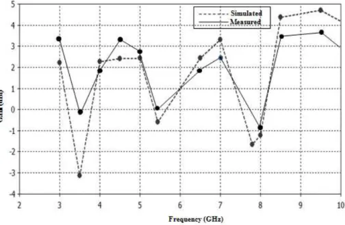
The measured gain vs simulated gain of the antenna is shown in Fig. 13. The gain pattern
indicates that the antenna has a stable gain over the entire UWB except at notched bands where sharp
dips are observed. The measured gain of the antenna ranges from 3.3 dBi to 3.8 dBi and significant
drop in its magnitude is observed at three notched bands.
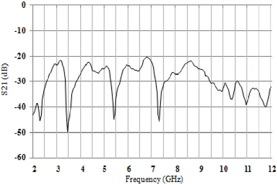
Fig. 14. Measured transfer function of proposed compact monopole UWB antenna.
Time domain characteristics of the antenna are also investigated as flat group delay and small
signal distortion is a primary requisite for UWB communication system [31].Time domain
characteristics of the proposed antenna are obtained by using a pair of similar antennas and carrying
out the measurements by placing them in face-to-face configuration at a distance of 50 cm, using two
ports of network analyzer. Fig. 14 shows the magnitude of the transfer function (S21). It is observed
that the magnitude of the transfer function is flat in UWB region of 3.1 to 10.6 GHz except at notched
bands.
The group delay of the antenna is shown in Fig. 15. It is seen that the group delay is constant over
the entire operating band except at the notched frequencies where the group delay is more than 2 ns.
The antenna establishes a good linear phase response except at notched bands. Good phase linearity
coupled with low dispersion indicates that the antenna is able to retain UWB pulse preserving
capability and thus is able to perform well throughout the UWB with desired band notched
characteristics.
III. CONCLUSION
This paper presents a novel compact UWB antenna of size 30 x 30 mm2 with triple band-notched
features fabricated on FR4 substrate. The proposed antenna is able to cover entire UWB spectrum
from 3.1 to 10.6 GHz with triple band notched functions. The three notched bands with center
frequency at 3.5 GHz, 5.5 GHz and 7.8 GHz have been obtained by etching two U-shaped slots and
one C-shaped slot on radiating patch and the microstripfeedline. U slots are used for WiMax band and
X band satellite communication while a C slot is used for WLAN band. The length of the slots is
taken to be one half of the guided wavelength of the center frequency of notched band. The H-plane
radiation pattern is omni-directional in nature while E-plane is almost bi-directional over the entire
bandwidth. The strength of the antenna lies in its compact design with stable radiation pattern and
gain over the entire UWB which makes it to be a good candidate for UWB applications especially in
miniaturization of modern communication devices.
REFERENCES
[1] Federal Communications Commission (FCC), Washington, DC, “First report and order in the matter of revision of
Part 15 of the commission’s rules regarding ultra-wideband transmission systems,” FCC02-48, Apr.22, 2002. [2] S. K. Mishra and J. Mukherjee, “Compact printed dual band-notched U-shaped UWB antenna,” Progress in
Electromagnetic Research C, Vol. 27, 169-181, 2012.
[3] Qing-Xin Chu and Ying-Ying Yang, “A compact ultra wide band antenna with 3.4/5.5 GHz dual band-notched
characteristics,” IEEE Transactions on Antennas and Propagation, Vol. 56, No. 12, 3637-3644, 2008.
[4] C. Y. Hong, C. W. Ling, I. Y. Tarn, and S. J. Chung, “Design of a planar ultra wide band antenna with a new
band-notch structure,” IEEE Transactions on Antennas and Propagation, Vol. 55, No. 12, 3391–3397, 2007.
[5] Y. C. Lin and K. J. Hung, “Compact ultra-wideband rectangular aperture antenna and band-notched designs,” IEEE Transactions on Antennas and Propagation, Vol. 54, No. 11, 3075–3081, 2006.
[6] Reza Zaker, Changiz Ghobadi, and Javad Nourinia, “Bandwidth enhancement of novel compact single and dual band-notched printed monopole antenna with a pair of L-shaped slots”, IEEE Transactions on Antennas and Propagation, Vol. 57, No. 12, 3978–3983, 2009.
[7] M. Mehranpour, J. Nourinia, Ch. Ghobadi, and M. Ojaroudi, “Dual band-notched square monopole antenna for
ultrawide band applications,” IEEE Antennas Wireless Propagation Letter, Vol. 11, 172–175, 2012.
[8] Yongfan Lin, Jingang Liang, Zimu Yang, Zhiyong Xu, and RuiWu,“A novel UWB antenna with dual-band notched
characteristics,” Progress in Electromagnetic Research Symposium Proceedings, Guangzhou, China, 1467-1470, 25-28, 2014.
[9] W. S. Lee, D. Z. Kim, K. J. Kim and J. W. Yu, “Wideband planar monopole antennas with dual band-notched
characteristics,” IEEE Transactions on Microwave Theory Technology, Vol. 54, No. 3, 2800-2806, 2008.
[11] G. P. Gao, Z. L. Mei, and B. N. Li, “Novel circular slot UWB antenna with dual band-notched characteristic,” Progress in Electromagnetic Research C, Vol. 15, 49-63, 2010.
[12] K.-H. Kim and S.-O. Park, “Design of the band-rejected UWB antenna with the ring-shaped parasitic patch,”
Microwave and Optical Technology Letters, Vol. 48, No. 7, 1310–1313, 2006.
[13] X. L. Liu, Y. Z. Yin, P. G. Liu, J. H.Wang, and B. Xu, “A CPW-fed dual band-notched UWB antenna with a pair of bended dual-L shape parasitic branches,” Progress in Electromagnetic Research, Vol. 136, 623–634, 2013.
[14] S. R. Emadian, C. Ghobadi, J. Nourinia, M. H. Mirmozafari, and J. Pourahmadazar, “Bandwidth enhancement of CPW-Fed circle-like slot antenna with dual band-notched characteristic,” IEEE Antennas and Wireless Propagation Letters, Vol. 11, 543–546, 2012.
[15] Peng and Chengli Ruan,“ Design and time-domain analysis of compact multi-band-notched UWB antennas with
EBG structures,” Progress In Electromagnetic Research B, Vol. 47, 339–357, 2013.
[16] Liu, Hao, and Ziqiang Xu, “Design of UWB monopole antenna with dual notched bands using one modified electromagnetic-bandgap structure,” The Scientific World Journal: 917965. PMC, 2013.
[17] Lalithendra Kurra, Mahesh P Abegaonkar, Ananjan Basu, and Shiban K Koul, “A band-notched UWB antenna using uni-planar EBG structure,” 7th European Conference on Antennas and Propagation (EuCAP), 2466-2469, 2013. [18] M. A. W. Nordin, M. T. Islam, and N. Misran, "Design of a compact ultrawideband metamaterial antenna based on
the modified split-ring resonator and capacitively loaded strips unit cell," Progress In Electromagnetic Research, Vol. 136, 157-173, 2013.
[19] Wen Tao Li, Yong Qiang Hei, Wei Feng, and Xiao Wei Shi, “Planar antenna for 3G/Bluetooth/WiMAXand UWB applications with dual band-notched characteristics,” IEEE Antennas and wireless Propagation Letters, Vol. 11, 61-64, 2012.
[20] Rezaul Azim, Mohammad Tariqul Islam, Norbahiah Misran, BaharudinYatim, and Haslina Arshad, “Design and Rrealization of a planar ultra wideband antenna with notch band at 3.5 GHz,” The Scientific World Journal, Vol. 2014, Article ID 563830, 7 pages, 2014.
[21] Ryu, Kenny Seungwoo, and Ahmed A. Kishk, “UWB antenna with single or dual band-notches for lower WLAN
band and upper WLAN band,” IEEE Transactions on Antennas and Propagation, Vol. 57, 3942-3950, 2009. [22] Schantz, Hans Gregory, Glenn Wolenec, and Edward M. Myszka,“Frequency notched UWB antennas,” IEEE
Proceedings, UWBST, 214-218, 2003.
[23] Zhou, H-J., B-H. Sun, Q-Zh Liu, and J-Y. Deng, “Implementation and investigation of U-shaped aperture UWB antenna with dual band-notched characteristics,” Electronics letters, Vol 44, No. 24, 1387-1388, 2008.
[24] Chu, Q-X., and Y-Y. Yang, “3.5/5.5 GHz dual band-notch ultra-wideband antenna,” Electronics Letters , Vol 44, No. 3, 172-174, 2008.
[25] Nguyen, Trang Dang, Dong Hyun Lee, and Hyun Chang Park, “Design and analysis of compact printed triple band
-notched UWB antenna,” IEEE Antennas and Wireless Propagation Letters, Vol. 10, 403-406, 2011.
[26] Deng, J-Y., Y-Z. Yin, Sh-G. Zhou, and Q-ZhLiu, “Compact ultra-wideband antenna with tri-band notched
characteristic,” Electronics Letters , Vol 44, No. 21, 1231-1233, 2008.
[27] Mahendra M Sharma, Jeetendra K Deegwal, Ashok Kumar, Mahesh c Govil, “Compact planar monopole antenna with quadruple band-notched characteristics,” Progress in Electromagnetic Research C, Vol. 47, 29-36, 2014. [28] Chao-ming Luo, Jing-song Hong, and Han Xiong, “A Tri-notched UWB antenna with low mutual coupling between
the band-notched structure,” Radioengineering, Vol. 22, No 4, 1233-1238, 2013.
[29] Qing-Xin Chu and Ying-Ying Yang, “A compact ultrawideband antenna with 3.4/5.5 GHz dual band-notched
characteristics,” IEEE Transactions on Antenna and Propagation, Vol. 56, No 12, 3637-3644, 2008.
[30] WU, Q., R Jin, J Gong, and M Ding, “Printed omni-directional UWB antenna with very compact size,” IEEE Transactions on Antennas and Propagation, Vol 56, 896 - 899, 2008.