Brazilian Microwave and Optoelectronics Society-SBMO received 11 July 2015; for review 15 July 2015; accepted 5 Nov 2015 Brazilian Society of Electromagnetism-SBMag © 2015 SBMO/SBMag ISSN 2179-1074
Abstract—An efficient design approach of directional couplers based multiplexers/demultiplexers for optical communication applications, by using an adapted artificial immune network algorithm for optimization (opt-AiNet), is presented and validated by using the beam propagation method. Two key multiplexers/demultiplexers based on planar waveguides and optical fiber, directional couplers, have been optimized in order to validate the efficiency and usefulness of the opt-AiNet.
Index Terms—Immune Network Algorithm, Evolutionary Algorithms, Beam Propagation Method, Frequency Domain, Photonic Devices.
I.INTRODUCTION
Directional couplers (DC) are devices composed by two parallel dielectric waveguides, where the
optical power transfers from one guide to another guide [1]. The coupling distance, where the
maximum power transfers from one guide to another occurs, is determined by the optical and
geometrical parameters of the coupler and also, by the operating wavelength [1]. They can be used as
power splitters with arbitrary power fraction at the output ports, depending on the length of the
coupler and their characteristics. They can also be used as two wavelength multiplexer and
demultiplexer devices in wavelength division multiplexing (WDM) systems if the corresponding
coupling lengths for the two wavelengths are judiciously chosen in association with the device length.
The couplers design for multiplexing/demultiplexing purposes can be considered as an inverse
problem, which is usually performed by a wide number of trials, leading it to a tedious iterative
process that also consume a worktime.
In [2], an artificial neural network was proposed to overcome this non trivial process, and in [3]an
artificial immune network (opt-AiNet) system was adapted to optimize optical fiber directional
couplers. Herein, this opt-AiNet was also extended to design novel multiplexers/demultiplexers for
planar directional couplers for different CWDM wavelengths, showing the algorithm adaptation for
different problems and its efficiency for these non-intuitive optimizations.
Artificial Immune Network Design of Optical
Multiplexers/Demultiplexers
Carlos H. Silva-Santos,
São Paulo Federal Institute of Education, Science and Technology - IFSP, campus Itapetininga, 18202-000, Brazil, E-mail: [email protected]
Vitaly F. Rodríguez-Esquerre
Department of Electrical Engineering, Federal University of Bahia, UFBA, 40210-630, Brazil, E-mail: [email protected]
Hugo E. Hernández-Figueroa
Brazilian Microwave and Optoelectronics Society-SBMO received 11 July 2015; for review 15 July 2015; accepted 5 Nov 2015 Brazilian Society of Electromagnetism-SBMag © 2015 SBMO/SBMag ISSN 2179-1074
The artificial immune network algorithm for optimization and its adaptations is presented in section
II, couplers and multiplexers based in, are presented in section III, divided into planar and optical
fiber based items. Optimization results are given in section IV and finally the conclusions and work in
progress are presented.
II. IMMUNE NETWORK ALGORITHM FOR OPTIMIZATION – OPT-AINET
The Artificial Immune System (AIS) researchers and techniques have recently been expanded by
the benchmarking and tackling real-world applications [4]-[10]. According to [5], its story starts on
90's, when Forrest et al. [6] proposed a selection algorithm based on the generation of T-cells to
discriminate the antigen-antibody, called negative selection method. Therefore, the AIS are
methaheuristics techniques being widely explored in different applications, in economy analysis [7],
[8] and environmental techniques and processes improvements [9], [10].
The artificial immune network algorithm is one of the computational representation from the
vertebrate immune system, being a general schematic between the antigenic and antibody relations
[11], [12], [13]. Herein, is considered the number of antibodies fabricated in B-cells (Bone Marrow)
to identify their geometrically complementarity, also called affinity [13].
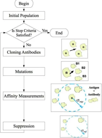
The affinity level implies in the B-cell expansions (Figure 1), consequently, in the fabrication of
new antibodies by cloning, which its can suffer some random changes (mutations) in their
characteristics. It is an important concept adapted in the algorithm as important immune operator to
improve the optimization performance. These new antibodies and antigenic population will be
aggregated in the previous population to re-measure the affinities fees again.
Fig. 1. Simplified vertebrate immune system schematic [3],[13].
Considering this full population, some macrophage or T-cell are signalized to suppress some
antibodies/antigen, keeping in account a pre-determined region to evaluate the individuals affinities
and maintain only best antibodies [11]. This complete procedure of antigenic interconnection, clonal
expansion, mutation and cell selections is called clonal selection [12].
From this macro vertebrate immune system description, this work presents an adapted artificial
immune system, as shown in Fig. 2, under the opt-AiNet version, combining two different mutation
operators and an updated antibody suppression process to improve the convergence performance for
Brazilian Microwave and Optoelectronics Society-SBMO received 11 July 2015; for review 15 July 2015; accepted 5 Nov 2015 Brazilian Society of Electromagnetism-SBMag © 2015 SBMO/SBMag ISSN 2179-1074
The mutations are the combination of gene duplication and spatial Gaussian distribution [14], in
proportion the proportion of 20% and 80%, respectively. These relations were determined after some
benchmark tests [14],[15], [16]. The suppression affinity fee was changed to consider an acceptable
coupling average value for each attribute in the group of all individuals during the generation. This resource introduces flexibility for applications where the individual’s attributes are pre-determined in different intervals orders of numerical values.
Fig. 2. Adapted Opt-AiNet algorithm dataflow.
The herein Opt-AiNet algorithm presented has been developed under the Object Orientation
definitions by the C++ language, allowing its reuse in further different applications, and follows the
main theoretical aspects described in [12],[13],[17],[18]. Furthermore, this computational
implementation is fast enough to be disregarded in computational powerful requirements analysis,
being intrinsically related only to the objective functions. For examples, when the numerical methods,
such as FDTD or FEM, are adopted to model any electromagnetic devices as presented in
0[16],[19],[20], [21].
III. COUPLER BASED MULTIPLEXER
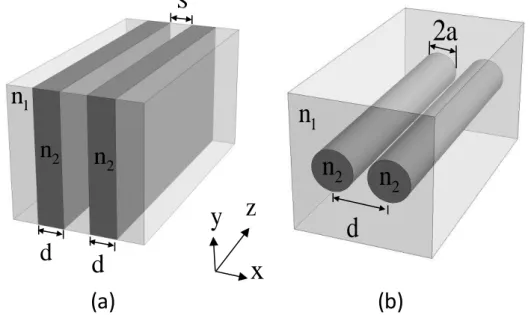
The coupler based multiplexer/demultiplexers, as shown in Fig. 3, separate or combine two
Brazilian Microwave and Optoelectronics Society-SBMO received 11 July 2015; for review 15 July 2015; accepted 5 Nov 2015 Brazilian Society of Electromagnetism-SBMag © 2015 SBMO/SBMag ISSN 2179-1074
even integer numbers (or vice-versa). This ensures that each power signal will be present only in one
of the outputs. The operation principle can be seen in Fig. 4, where n = 5 (odd) and m = 4 (even).
2
n
2
n
1
n
S
d
d
2
a
1
n
2
n
2
n
d
x
y
z
(b)
(a)
Fig. 3. Directional couplers in a) planar and b) optical fiber based waveguides.
z
P z
1 2
5
4
L
Lc
Lc
2
Lc
1
Lc
1
2Fig. 4. Operation principles in demultiplexing directional couplers. The device length is chosen to be
odd and even times the coupling length at each frequency.
These parameters are related to geometrical equations used to model the directional couplers, being
important to present the Lc calculations for the planar and optical fiber directional couplers separately.
At first, the planar waveguide, shown in Fig. 3. (a), operating in C and E bands. It presents the input
signal along the propagation direction is given by (1) and (2),
2 1 incos
Brazilian Microwave and Optoelectronics Society-SBMO received 11 July 2015; for review 15 July 2015; accepted 5 Nov 2015 Brazilian Society of Electromagnetism-SBMag © 2015 SBMO/SBMag ISSN 2179-1074
2 2 insen
P P Cz (2)
where, P1 and P2 are the waveguide output power. Pin is the input power, C is the coupling factor
obtained by the coupling mode theory and z is the distance measured since the input port. Therefore,
the total power transfer to the other waveguide occurs when C.z = π/2. Consequently, the coupling
distance can be expressed by (3).
2 c L C (3)
For planar waveguide DCs, the coupling factor C is given by (4),
22 2
/ 2 (1 2 / )( )
xS
x x
z x x x
k e C
k d d k
(4)
where d is the waveguide width, S the distance between the waveguides, kx= k0 (n2 2−
neff 2
)0.5, αx= k0
(neff 2−
n1 2
)0.5 and k0 = 2π/ is the wave number in free space, is the wavelength, n1 and n2 is the
guide and substrate refractive indexes, respectively. The neff is the effective index obtained by solving
the transcendental equation (5).
tan / 2 x
x x k d k (5)
The coupling length in optical fiber DCs shown in Fig. 2. (b) can be obtained in an approximate
way by using the analytical solution given in [1],
2 2 2 2
1 1
2 0
( ) ( / ) a n V K W Lc
U K Wd a
(6)
where, W= ak0(neff2-n12)1/2, U = ak0 (n22-neff2)1/2, a is the optical fiber radius, d is the distances between the fibers from their centers, k0 is the free space wavenumber given by 2π/ , is the free space wavelength, n1 and n2 are the refractive indexes of the core and the cladding,
respectively. K0 and K1, are the Bessel functions.
The neff is the effective index obtained by solving the transcendental equation (5).
0 0
1 1
J U K W
UJ U WK W (7)
where J0and J1 are Bessel functions. We can observe the nonlinear relation among all the
parameters.
IV. NUMERICAL RESULTS
The first multiplexer/demultiplexer device designed is the planar waveguide operating in
wavelengths of 1.41 µm and 1.55 µm. The device length has been imposed as a restriction, in this way
L, should be 200 µm. The AIS algorithm presented satisfactory results for the convergence and for the
Brazilian Microwave and Optoelectronics Society-SBMO received 11 July 2015; for review 15 July 2015; accepted 5 Nov 2015 Brazilian Society of Electromagnetism-SBMag © 2015 SBMO/SBMag ISSN 2179-1074
Lc2 = 49.6727 µm. Thus, the final mux/demux proportion is L ≈ 3·Lc1 and 4·Lc2.
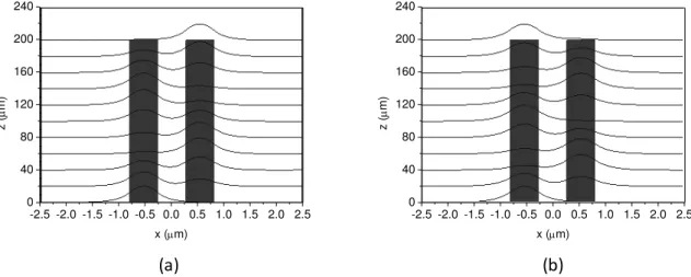
In Fig. 5. it is possible to observe the propagation of the input signal which is placed at the left port,
and after the propagation it can reach the left or the right port, depending on the operating wavelength.
-2.5 -2.0 -1.5 -1.0 -0.5 0.0 0.5 1.0 1.5 2.0 2.5 0
40 80 120 160 200 240
z (
m)
x (m)
-2.5 -2.0 -1.5 -1.0 -0.5 0.0 0.5 1.0 1.5 2.0 2.5 0
40 80 120 160 200 240
z (
m)
x (m)
(b) (a)
Fig. 5. Spatial distribution of the propagated fields along the designed directional coupler based on planar waveguides in (a) =1.41 µm and (b) =1.55 µm.
The results obtained for the planar mux/demux are summarized in Table I.
TABLE I.PLANAR MUX/DEMUX WITH L=200m(S = d = 0.538021 µm)
Operating Wavelength n1() n2() Lc() L = 200 m
= 1.41 m 2.99259 3.22757 66.0018 µm 3.030Lc = 1.55 m 2.97971 3.21469 49,6727 µm 4.026Lc
The second application is the design of multiplexer/demultiplexer based on optical fiber
waveguides. In this case, two CDWM wavelengths were chosen, being 1 = 1.2λ m and 2 = 1.5λ m. The maximum device length was fixed to be L = 1 mm. The core and cladding of the optical fiber were considered to be 13.5% GeO2−86.5% SiO2 and quenched SiO2, respectively.
The wavelength dependence of the refractive indexes has been taken into account by using the
Sellmeier coefficients given in [22]. The values of a and d were computed by using the proposed AIS.
The objective functions, for both applications, have penalties and bonuses in accordance to the limits
of Lc1, Lc2, P1 and P2. For Lc1 and Lc2 the objective functions must be higher than 0 and lower than
Lc limits, when these conditions are not satisfied, the final objective value is given by
1
.
2 fit
Lc LcFrom the initial conditions, power outputs P1 and P2 promote the final objective value. When P1
and P2 have values higher than 0.98 or lower than 0.002, the final value is given by
1 2
2
fit
P
P and, respectively. Otherwise, it implies in.The optimization convergence and the number of individuals are shown in Fig. 6, where the
Brazilian Microwave and Optoelectronics Society-SBMO received 11 July 2015; for review 15 July 2015; accepted 5 Nov 2015 Brazilian Society of Electromagnetism-SBMag © 2015 SBMO/SBMag ISSN 2179-1074
times in each iteration (the population size was limited to 144 individuals). A mutation fee of 7% and
2% with Gaussian distribution and Genical Duplication, respectively, was used. This algorithm was
executed adopting 1,000 iterations. The optimization runtime takes, in average, 29 seconds.
0 200 400 600 800 1000
0 3 6 9 12 15
Numb
er
o
f I
nd
iv
id
ua
ls
Generations
Number of Individuals
0 200 400 600 800 1000
0.0 0.2 0.4 0.6 0.8 1.0
Con
ve
rg
en
ce
Generations
Optimization Convergence
(a) (b)
Fig. 6. The (a) convergence and (b) number of individuals in mux/demux based optical fiber waveguides.
From the optimization process with AIS the best optimized values were achieved when a = 1.582 m and d = 4.6λ87 m, respectively, leading to coupling lengths of Lc1 = 470.31 m and Lc2 = 314.27 m for 1 = 1.2λ m and 2 = 1.5λ m, respectively. By using m = 2 and n = 3 the device length is L = 941 m which is smaller than 1 mm.
In order to validate these results, the beam propagation method in frequency domain [23] has been
used to simulate the propagation of the fundamental mode along this coupler. The results are shown in Fig. 7 and 8. It can be observed that the field corresponding to 1 = 1.2λ m appears at the same input fiber after propagating λ41 m (Fig. 7), while for 2 = 1.5λ m the field appears at the second fiber after propagating λ41 m (Fig. 8). Another observation is that overlapping field in both cases can be considered negligible. Several other configurations have been obtained for different two CDWM wavelengths ( 1, 2, Lc1, Lc2, m, n, L) and presented satisfactory results.
Brazilian Microwave and Optoelectronics Society-SBMO received 11 July 2015; for review 15 July 2015; accepted 5 Nov 2015 Brazilian Society of Electromagnetism-SBMag © 2015 SBMO/SBMag ISSN 2179-1074 Fig. 7 Spatial distribution of the field intensity at the input and output of the coupler for 1 = 1.2λ m (a) z = 0 and (b) z =
λ41 m.
(a)
(b)
Fig. 8 Spatial distribution of the field intensity at the input and output of the coupler for 2 = 1.5λ m (a) z = 0 and (b) z =
λ41 m.
The results obtained for the optical fiber mux/demux are summarized in Table II.
TABLE II.OPTICAL FIBER MUX/DEMUX WITH L=941m(a = 1.582µm and d = 4.6987µm)
Operating Wavelength n1() n2() Lc() L = 941 m
= 1.29 m 1.4683 1.4474 470.31 µm 2.0008Lc = 1.59 m 1.4651 1.4439 314.27 µm 2.994Lc
V. CONCLUSIONS
The use of efficient parallel platforms and algorithms may certainly help to reduce substantially
the CPU time. In this work, the AIS in conjunction with analytical formulae have been used to
design planar and optical fiber couplers based CDWM multiplexers/demultiplexers in an efficient
way. The optimizations presented here showed a satisfactory convergence, optimized results with
the constraints imposed and short runtime. The results were validated by using the FEM-BPM.
ACKNOWLEDGMENTS
The authors thank CePOF/UNICAMP/FAPESP, INCT FOTONICOM/CNPq/FAPESP, FAPESP
(under the processes 2005/55958-8 and 2006/57074-2) and CNPq under the process 311774/2012-1,
CAPESP, FAPESB.
REFERENCES
[1] K. Okamoto, Fundamentals of Optical Waveguides, Academic Press, 2005.
Brazilian Microwave and Optoelectronics Society-SBMO received 11 July 2015; for review 15 July 2015; accepted 5 Nov 2015 Brazilian Society of Electromagnetism-SBMag © 2015 SBMO/SBMag ISSN 2179-1074 [3] C. H. Silva-Santos, V. F. Rodríguez-Esquerre, and H. E. Hernández-Figueroa, "An Artificial Immune System for Optical Fiber Based Directional Couplers Multiplexer/Demultiplexers Design," in Latin America Optics and Photonics Conference, OSA Technical Digest (CD) (Optical Society of America, 2010), paper PDPTuJ5.
[4] E. Hart, Emma; J. Timmis. “Application areas of AISμ The past, the present and the future.” Applied soft computing, v. 8, n. 1, p. 191-201, 2008.
[5] D. Dasgupt; S. Yu; F. Nino. Recent advances in artificial immune systems: models and applications. Applied Soft Computing, v. 11, n. 2, p. 1574-1587, 2011.
[6] S. Forrest, A.S. Perelson, L. Allen, R. Cherukuri, Self–nonself discrimination in a computer, IEEE Symposium on Research in Security and Privacy, Los Alamitos, CA, 1994.
[7] M. Basu. Artificial immune system for combined heat and power economic dispatch. International Journal of Electrical Power & Energy Systems, v. 43, n. 1, p. 1-5, 2012.
[8] M. Shukla; S. Jharkharia. An inventory model for continuously deteriorating agri–fresh produce: an artificial immune system–based solution approach. International Journal of Integrated Supply Management, v. 9, n. 1, p. 110-135, 2014.
[9] O. Erdinc; M. Uzunoglu. Optimum design of hybrid renewable energy systems: overview of different approaches. Renewable and Sustainable Energy Reviews, v. 16, n. 3, p. 1412-1425, 2012.
[10] S. Li, et al. Self-adaptive obtaining water-supply reservoir operation rules: Co-evolution artificial immune system. Expert Systems with Applications, v. 41, n. 4, p. 1262-1270, 2014.
[11] L. N. de Castro, “Fundamentals of Natural Computingμ Basic Concepts, Algorithms, and Applications, Chapman & Hall/CRC, 2006. [12] L. De Castro, Fundamentals of Natural Computing: An Overview, Physics of Life Reviews (4) 1-36, 2007
[13] L. N. de Castro, J. Timmis, “Artificial Immune Systemsμ A New Computational Intelligent Approach”, Springer Verlag, London, 2002.
[14] C. H. Silva-Santos, M. S. Gonçalves, H. E. Hernández-Figueroa, “Designing Novel Photonic Devices by Bio-Inspired Computing”, IEEE Photonics Technology Letter, Vol. 22, Issue 15, 2010.
[15] C. H. Silva-Santos, K. Claudio, M. S. Gonçalves, J. R. Brianeze, H. E. Hernández-Figueroa, “Bio-Inspired Algorithms Applied to
Microstrip Antennas Design”, Journal of Computational Interdisciplinary Science, Vol. 1, Issue 2, 2009.
[16] J. R. Brianeze, C. H. Silva-Santos, H. E. Hernández-Figueroa. "Multiobjective evolutionary algorithms applied to microstrip antennas design algoritmos evolutivos multiobjetivo aplicados a los proyectos de antenas microstrip." Ingeniare. Revista chilena de ingeniería 17, 3, 288-298, 2009.
[17] J. Timmis, A. Hone, T. Stibor, E. Clark, “Theoretical advances in artificial immune systems”.Theoretical Computer Science, 403(1), 11-32, 2008.
[18] D. Dasgupta, S. Yu, F. Nino, “Recent advances in artificial immune systemsμ models and applications.”Applied Soft Computing, 11(2), 1574-1587, 2011.
[19] A. D. Sisnando, et al. "Artificial immune system optimisation of complete bandgap of bidimensional anisotropic photonic crystals." IET Optoelectronics 9.6 (2015): 333-340.
[20] A. D. Sisnando, et al. "Power Coupling Optimization by Artificial Immune System." Integrated Photonics Research, Silicon and Nanophotonics. Optical Society of America, 2014.
[21] C. H. Silva-Santos, H. E. Hernandez-Figueroa. "Parallel bio-inspired algorithms in computational electromagnetics applications." 2011 SBMO/IEEE MTT-S International Microwave and Optoelectronics Conference (IMOC 2011). 2011.
[22] M. Adams, An Introduction to Optical Waveguides, Wiley, 1986.
[23] Y. Tsuji and M. Koshiba, “Finite element beam propagation method with perfectly matched layer boundary conditions for
![Fig. 1. Simplified vertebrate immune system schematic [3],[13].](https://thumb-eu.123doks.com/thumbv2/123dok_br/18888030.424299/2.892.260.639.721.879/fig-simplified-vertebrate-immune-system-schematic.webp)