Abstract— An optimized design for the spanner shape regular hexagonal monopole (RHM) patch antennas has been reported to yield ultra wide band (UWB) impedance bandwidth. Impedance and radiation characteristics are presented and discussed. From the results, it has been observed that, the impedance bandwidth, defined by 10 dB return loss, can reach a value of 8.63GHz. A rectangular slit in the radiating patch is used to reduce the lower-edge frequency resulting in improved bandwidth. This technique yields the ability to construct a smaller antenna in comparison to a simple printed planar monopole antenna for a given frequency range. The printed metallic patch is defected for increasing the operating bandwidth. The antennas considered in this paper operate between 2.95 GHz to 11.58 GHz, making them suitable for numerous DECT, WLAN, remote sensing, radar, imaging, localization and medical applications. The etched area of the antenna can be used for communication circuit components.
Index Terms— hexagonal monopole, printed circuit, rectangular slot, spanner antenna, UWB.
I. INTRODUCTION
US - Federal Communication Commission (US-FCC) released a 10dB bandwidth of 7.5 GHz (3.1 –
10.6 GHz) for ultra–wideband (UWB) wireless communication [1]. With the development of the high
data rate wireless communication systems, antenna engineers face an increasing demand for smaller
antennas which still retain broadband characteristics. Printed planar monopole antennas have become
very popular due to their attractive features of low profile, light weight, easy fabrication, and
conformability to mounting hosts, large bandwidth and radiation properties [2], [3]. High–
performance miniaturized front-end printed circuit boards are essential in portable systems [4]. Planar
Microstrip feed Spanner Shape Monopole
Antennas for Ultra Wide Band Applications
Tapan Mandal1 and Santanu Das 2
1Department of Information Technology,
Government College of Engineering and Textile Technology, Serampore, Hooghly, India, PIN-712201 2Department of Electronics & Tele-Communication Engineering,
Ultra Wide Band (UWB) monopole antennas with rectangular, square, disk, elliptical and triangular
shapes have been reported [5-9]. The Hexagonal monopole antennas are found to have 10 dB return
loss bandwidth for UWB application [10], [11]. Rectangular slot with resistive load hexagonal for
GPR application has been presented [12]. Surface current distribution analysis is very effective to
investigate the radiation area of the antenna and to give guidance to design and optimization [13]. The
antennas integrated on a printed circuit board can be viewed as a suspended monopole broad band
antenna. The existence of many possible current modes explains the reason of such a broad antenna
bandwidth. The current modes that could exist on a circular metal patch are in the form of higher
order Bessel functions of the first kind, where current is less at the center of the patch and mostly
concentrated on its periphery [13].
In this paper, miniaturized spanner shape monopole antenna characteristics are proposed. It is an
enhancement of the work presented in [11]. The design initially begins with a printed regular
hexagonal monopole antenna (PRHMA). The inner aperture area of the spanner shape can be used for
communication circuit components. The proposed antenna has advantages of low cost, compact and
easy fabrication due to simple configuration. The simulation is carried out by a Method of Moment
(MoM) based IE3DTM simulator. The simulation results confirm ultra wideband (UWB)
characteristics of the antenna. The detail simulation responses are presented and discussed here.
In this research work, the return loss measurements are taken out by Agilent make Vector Network
Analyzer (N5230A).
The organization of this paper is as follows. Section II presents the configuration design criteria of
the proposed antenna. The details of the antenna parameters and observations are given in section III.
Section IV concludes the findings of this paper.
II. ANTENNA CONFIGURATION
For UWB antennas, lower band edge frequency and entire band width become the design
parameters, instead of resonance or operating frequency [2]. The design initially begins with a
microstrip fed printed regular hexagonal monopole antenna (PRHMA). The prototype PRHMA
element is designed on a substrate having dielectric constant ( r) = 4.4, thickness (h) = 1.59 mm and
loss tangent = 0. 002 (Fig. 1). Provided that the lower frequency (fl) operation is 2.98 GHz, the entire
length (L) and width (W) of the proposed antenna [10, 14-16] are calculated by equations (1) and (2).
Finally, L×W is selected as 31×52 mm2, approximately half an effective wavelength of the lowest
operating frequency [15].
L =
( 1)
2
2 r l
c
f
ε
+(1)
3
where c is the velocity of light in free space. The lower band edge frequency (fl) has been determined
for UWB using formulas [2], [10] given in equation (3)
(
)
7.2
l
c
f
H
r
p
λ
=
=
+ +
(3)where H is the height from ground plane edge to the top of the hexagon and r is the radius of an
equivalent cylindrical monopole antenna in cm and p is the length of the feed line in cm. With
reference to configurations in Fig. 1 with side length (Lp), the dimension of height (H) and radius (r)
of the equivalent cylindrical monopole antenna are obtained by equating their areas as follows:
3L r =
4 p
Π
(4)3 p
H
=
L
(5)2 p p
D = L (6)
Fig.1. A regular hexagonal shape monopole antenna Fig.2. A defected regular hexagonal shape (spanner shape) monopole antenna
The Zelend IE3D is used for further fine tuning of dimensions [17]. The patch has a compact size of
26mm×22.5 mm×1.59mm. The diameter (Dp) of the monopole element is 26 mm, height (H) = 22.5
mm and side length (Lp) = 13 mm. It is fed via a 50 ohm microstrip line with a width of Wf = 2.8 mm.
A rectangular ground plane (Lg = 28 mm × Wg =13.5 mm) is taken on the other side of the substrate
which stops (S) 0.5 mm short of the beginning of the monopole element. It is noted that the detailed
dimensions of the radiator and the ground plane result in a horizontal dipole of a length equal to a half
wavelength, which is elevated from the ground by about a quarter wavelengths at fl.
In another form (Fig. 2) the monopole metallic patch element is made on the same substrate with
the dimensions same as before. However the hexagonal element is defected by a rectangular shape.
parametric study. It is observed from the simulation that the current on the hexagonal patch radiator
are mostly concentrated on its periphery with very low current density towards center. The idea of
cutting out a rectangular slot derives from the examination of current distribution of hexagonal patch
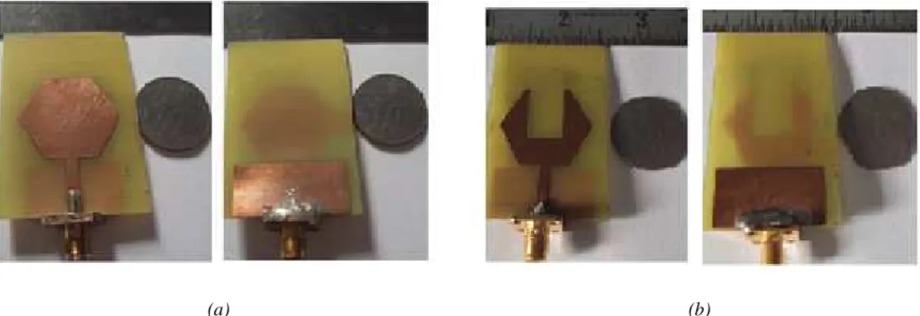
antenna. A prototype spanner antenna is proposed that occupies only 65% area of the PRHMA and
fabricated and tested. The fabricated prototype and spanner antennas are shown in Fig. 3.
(a) (b)
Fig. 3. Fabricated antennas (a) prototype PRHMA (b) spanner antenna; Top plane (left side), bottom plane (right side)
III. RESULTS AND DISCUSSIONS
A. Return Loss
Here the BW of the antenna depends on how the impedance of various modes of the patch is
matched with feed line. For the PRHMA the return loss characteristics are shown in Fig. 4. It exhibits
simulated impedance BW of 7.66 GHz (2.98 – 10.64 GHz) (defined by 10 dB) having a ratio 3.57:1.
The measured response yields the BW of 6.63 GHz (3.07 - 9.7 GHz). The discrepancy between
simulated and measured results should be mostly attributed to the loss tangent (tan ) of the substrate,
tolerance in manufacturing. Thus it may be considered as a good Ultra Wide Band (UWB) antenna.
Fig.4 Return loss characteristics of Fig. 1
The return loss characteristics of spanner shape (Fig. 2) are shown in Fig. 5 and Fig. 6. It is found
return loss decreases (absolute value increases). The length of the defected slot can be also used to
extend the lower edge frequency of the impedance bandwidth.
Fig.5. Simulated return loss characteristics for Fig.6. Simulated return loss characteristics for
various lengths of Ws variouswidths of Ls
The defected length (Ls) also influences the bandwidth of the antenna and degrades the higher
frequency. With the rectangular slot (Ls = 10 mm and Ws = 15.25 mm) provides the best impedance
matching and maximum bandwidth. The return loss characteristics give an impedance bandwidth of
8.63 GHz (11.58-2.95GHz) with a ratio of about 3.92:1 for optimum values of Ls = 10 mm and Ws =
15.25 mm. The measured and simulated responses are illustrated in Fig. 7. The measured
characteristic shows 10.04 GHz (2.93 – 12.97 GHz) impedance BW which cover the entire UWB
frequency range. The measured results are in agreement with the simulated results. It is observed that
the measured impedance bandwidth of spanner monopole has been enhanced by 3.41 GHz with
respect to the single patch monopole MSA.
Fig.7. Comparison of the return loss characteristics (simulation and measured) of PRHMA and spanner shape monopole antenna
TABLE I: THE ANTENNA DESIGN PARAMETERS
Ls (mm) 8 Ws15.25 (mm) fl (GHz) 2.93 fh11.33 (GHz) B.W (GHz) 8.40
10 15.25 2.95 11.58 8.63
12 15.25 2.99 10.52 7.53
10 17.25 2.92 10.71 7.79
10 19.25 2.87 10.56 7.69
While comparing the results in Fig. 5 and Fig. 6, it is apparent that for the spanner and PRHMA
antenna, longest current path on the patch is approximately half the wave length at the lowest band
frequency. Further simulation shows that the slot perimeter of the spanner antenna is half wave length
of the lowest band frequency. If the slot perimeter becomes more than of half wave length then
impedance mismatches at 5.45 GHz and the second mode resonant frequency will not appear in UWB
band.
B. Radiation Pattern
The influences of the slot on the radiation patterns has also been investigated. Fig. 8 shows co-polar
and cross-polar radiation patterns of the antenna at 3 GHz and 8.5 GHz.
At 3 GHz (a) E-plane pattern At 3 GHz (b) H-plane pattern
At 8.5 GHz (a) E-plane pattern At 8.5 GHz (b) H-plane pattern
At lower frequencies H-plane radiation patterns are omnidirectional, whereas in E-plane, it is a
figure of eight because of very small ground plane. Radiation patterns, at higher frequencies, their
occurs little change in the H-plane pattern however in the E-plane reduces to an omnidirectional one
with slight increase in its cross polarization level. It is noted that adding a slot in the radiating patch
does not affect the radiation pattern in the H-plane. Thus it may be considered as a good UWB
antenna.
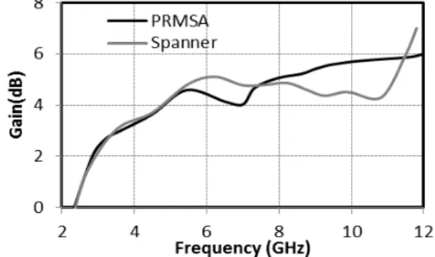
C. Gain and Efficiency
The efficiency and gain of the proposed antennas are shown in Fig. 9 and Fig. 10 respectively. It
can be seen that the proposed antenna have almost the same efficiency. Therefore the slot does not
have appreciable effects on the performance throughout entire operation band. But the antennas
provide more than 90% antenna efficiency. The spanner antenna has lower gain at the high frequency
band. At higher frequencies, there are rapid variations of surface currents along the periphery of the
patch. This decrease of gain at higher frequency can be attributed partially to the increase in losses
and to the surface current variation between various modes of the antenna configuration. However,
the gain variation of the spanner antenna is less than 1.5 dB from PRHMA throughout the whole
UWB frequency. For practical applications in UWB systems, the slot region may be used for RF
circuits without affecting antenna operation subject to further invertigation. The overall metallic area
of this antenna is reduced by 35% as compared to a PRHMA.
Fig. 9. Simulated antenna efficiency Vs. frequency Fig. 10. Simulated gain Vs. frequency of proposed
of proposed antenna antenna
IV. CONCLUSION
A spanner shape hexagonal monopole element is proposed for UWB communication in the range of
3.1 to 10.6 GHz. Parametric studies of the antenna characteristics are presented, and the return loss
characteristics are discussed and compared with the prototype hexagonal monopole antenna. It is
noted that the introduction of a rectangular slot in the radiating patch can be used as a compact printed
spanner planar monopole antenna. The measurement results also yield improvement of impedance
bandwidth from 6.63 GHz to 10.04 GHz with respect to prototype antenna. The defected hexagonal
(65% of the hexagonal element area). The inner aperture area can be used for communication circuit
components. Therefore the proposed antenna can be useful for various UWB applications.
ACKNOWLEDGMENT
This work is funded by Council of Scientific & Industrial Research (CSIR), New Delhi, India.
REFERENCES
[1] First Report and Order, “Revision of Part 15 of the commission’s Rule Regarding Ultra-Wideband Transmission System FCC 02 -48”, Federal Communications Commission, 2002.
[2] Kumar. G and K. P. Ray, Broad Band Microstrip Antennas, Norwood, MA, Artech House, 2003
[3] C. C. Lin, Y.C. Kan, L.C. Kuo, and H. R. Chuang, “A Planar Triangular Monopole Antenna for UWB Communication”, IEEE Microwave Wireless Compon Lett., vol.15, pp. 624- 626, 2005.
[4] H. Y. Yang, “Miniaturized Printed Wire Antenna for Wireless Communication,” IEEE Antenna Propag. Lett., vol. 4, pp. 358-361, 2005.
[5] C.Y. Huang and W.C. Hisa, “Planar Elliptical Antenna for Ultra –Wide Band Communication”, Electron Lett., vol.41, pp. 296-297, 2005
[6] M. John and M.J Amman, “Optimization of Impedance Bandwidth for the Printed Rectangular Monopole Antenna”, Microwave Opt Technical Lett.,vol.47, pp.153 – 154, 2005.
[7] M. J. Ammann, “Control of the Impedance Bandwidth of Wide Band Planar Ponopole Antenna using a Beveling Technique”, Microwave Opt Technical Lett., vol. 30, pp. 229-231, 2001
[8] C. Zhang and A. E. Fathy, “Development of an Ultra – Wide Band Elliptical Disk Planar Monopole Antennas with Improved Omni-directional Performance using a Modified Ground”, IEEE Int. Antenna Propagation Symp Dig., Alburqueque, NM. pp. 1689 – 1692, 2006.
[9] Z. N. Chen, T.SP. See, and X. M. Qing, “Small Printed Ultra Wide Band with Reduced Ground Plane Effect,”IEEE Trans. Antenna Propag., vol. 55, no.2, pp.383-388, Feb.2007.
[10] K.P.Roy and S.Tiwari, “Ultra Wide Band Printed Hexagonal Monopole Antennas” IET Microwaves, Antenna and Propagation, vol. 4, Iss. 4, pp. 437-445, 2010.
[11] Abdo Abdel Monem Shaalan and M. I. Ramadan, “Design of a Compact Hexagonal Monopole Antenna for Ultra- Wideband Applications”, J Infrared Milli Terahz Waves, vol. 31, pp. 958–968, 2010.
[12] A. A. Pramudita, A. Kurniawan, A. Bayu Suksmono “Hexagonal Monopole Strips with Rectangular slot for 100 -1000 MHz SFCW GPR application”, International Journal of Antenna and Propagation, pp.1-6, 2008.
[13] N.C. Azenui and H.Y.D.Yang, “A Printed Crescent Patch Antenna for Ultra-wide band Applications”, IEEE Antenna and propagation letter, Vol. 6, pp.113-116, 2007.
[14] J.X. Huang, F.S. Zhang, H.H. Xie, L. Zhang and Y. Zhu “A Hexagonal Ring Antenna with Dual Tunable Band notches for Ultrawide band Applications”, Progress In Electromagnetics Research Letter, vol. 12, pp.151-159, 2009.
[15] A. M. Abbosh and M. E. Bailkowaski “Design of UWB Planar Band-notched using Parasitic Elements ”, IEEE Trans. Antenna Propag., vol. 57, no.3, pp.796-799, 2009.