AMTD
7, 5921–5951, 2014Characterization and testing of a new
environmental chamber
A. Leskinen et al.
Title Page
Abstract Introduction
Conclusions References
Tables Figures
◭ ◮
◭ ◮
Back Close
Full Screen / Esc
Printer-friendly Version Interactive Discussion
Discussion
P
a
per
|
Discus
sion
P
a
per
|
Discussion
P
a
per
|
Discussion
P
a
per
Atmos. Meas. Tech. Discuss., 7, 5921–5951, 2014 www.atmos-meas-tech-discuss.net/7/5921/2014/ doi:10.5194/amtd-7-5921-2014
© Author(s) 2014. CC Attribution 3.0 License.
This discussion paper is/has been under review for the journal Atmospheric Measurement Techniques (AMT). Please refer to the corresponding final paper in AMT if available.
Characterization and testing of a new
environmental chamber designed for
emission aging studies
A. Leskinen1, P. Yli-Pirilä2, K. Kuuspalo3, O. Sippula3, P. Jalava3, M.-R. Hirvonen3, J. Jokiniemi3,4, A. Virtanen2, M. Komppula1, and K. E. J. Lehtinen1,2
1
Finnish Meteorological Institute, P.O. Box 1627, 70211 Kuopio, Finland
2
University of Eastern Finland, Department of Applied Physics, P.O. Box 1627, 70211 Kuopio, Finland
3
University of Eastern Finland, Department of Environmental Science, P.O. Box 1627, 70211 Kuopio, Finland
4
VTT Technical Research Centre of Finland, P.O. Box 1000, 02044 VTT, Espoo, Finland
Received: 11 April 2014 – Accepted: 3 June 2014 – Published: 13 June 2014
Correspondence to: A. Leskinen ([email protected])
AMTD
7, 5921–5951, 2014Characterization and testing of a new
environmental chamber
A. Leskinen et al.
Title Page
Abstract Introduction
Conclusions References
Tables Figures
◭ ◮
◭ ◮
Back Close
Full Screen / Esc
Printer-friendly Version Interactive Discussion
Discussion
P
a
per
|
Discus
sion
P
a
per
|
Discussion
P
a
per
|
Discussion
P
a
per
|
Abstract
A 29 m3 Teflon chamber, designed for aging studies of combustion aerosols, at the University of Eastern Finland is described and characterized. The chamber belongs to a research facility, called Ilmari, where small-scale combustion devices, a dynamome-ter for vehicle exhaust studies, dilution systems, the chamber, as well as cell and animal
5
exposure devices are side by side under the same roof. The small surface-to-volume ratio of the chamber enables reasonably long experiment times, with particle wall loss rate constants of 0.088, 0.080, 0.045, and 0.040 h−1 for polydisperse, 50, 100, and 200 nm monodisperse aerosols, respectively. The NO2photolysis rate can be adjusted
from zero to 0.62 min−1. The irradiance spectrum is centered at 365 nm and the
maxi-10
mum irradiance, produced by 160 blacklight lamps, is 29.7 W m−2, which corresponds to the UV irradiance in Central Finland at noon on a sunny day in the midsummer. The temperature inside the chamber is uniform and can be kept at 25±1◦C when half of the
blacklights are on. The chamber is kept in an overpressure with a moving top frame, which prevents sample dilution and contamination from entering the chamber during
15
an experiment. The functionality of the chamber was tested with oxidation experiments of toluene, resulting in secondary organic aerosol (SOA) yields of 33–44 %, depending on the initial conditions, such as the NOxconcentration. The highest gaseous oxidation
product yields of 14.4–19.5 % were detected with ions corresponding to 2-butenedial (m/z 73.029) and 4-oxo-2-pentenal (m/z 99.044). Overall, reasonable yields of SOA
20
and gaseous reaction products, comparable to those obtained in other laboratories, were obtained.
1 Introduction
The atmospheric aerosols undergo changes in their physicochemical properties, such as size and chemical composition, during their residence in the atmosphere. These
25
AMTD
7, 5921–5951, 2014Characterization and testing of a new
environmental chamber
A. Leskinen et al.
Title Page
Abstract Introduction
Conclusions References
Tables Figures
◭ ◮
◭ ◮
Back Close
Full Screen / Esc
Printer-friendly Version Interactive Discussion
Discussion
P
a
per
|
Discus
sion
P
a
per
|
Discussion
P
a
per
|
Discussion
P
a
per
and evaporation, and photochemical reactions with atmospheric oxidants. During the aging a substantial amount of secondary organic aerosol (SOA) is formed, which is fur-ther oxidized with increasing aging time (e.g., Ziemann and Atkinson, 2012; Hallquist et al., 2009). This may lead to significant changes, e.g., in the health and climate rele-vant properties of the atmospheric aerosols.
5
The transformation processes have been studied extensively and for decades in environmental chambers with different designs (Wang et al., 2014; Platt et al., 2013;
Hallquist et al., 2009, and references therein). The most used chamber materials are glass, stainless steel, and Teflon. The glass and stainless steel walls are rigid so the chambers have a fixed volume, whereas a thin heat-sealable Teflon film enables the
10
construction of a collapsible bag, whose volume decreases as the sample is taken out. Teflon is also advantageous, because it is inert and withstands the mechanical stress when the chamber frequently collapses and expands.
The rigid walls are advantageous in experiments which are carried out at a pressure that is much different from the ambient pressure. However, when sample is taken out, 15
the concentrations in the chamber dilute, which affects, e.g., the reaction rates in the
chamber. In collapsible bags, the concentrations are not diluted during sampling, un-less there are inward leaks through the walls. This can be prevented by keeping the bag at a slight overpressure, so the flow through the possible cracks is rather outwards than inwards.
20
When photochemical reactions are to be studied, the chamber material must let through the relevant ultraviolet irradiation, such as sunlight in outdoor chambers or blacklight in indoor chambers. For Teflon films the penetration is high, whereas for glass, excluding quartz glass, the penetration is weaker.
In addition to chambers, the oxidation due to the aging processes can be done in
25
AMTD
7, 5921–5951, 2014Characterization and testing of a new
environmental chamber
A. Leskinen et al.
Title Page
Abstract Introduction
Conclusions References
Tables Figures
◭ ◮
◭ ◮
Back Close
Full Screen / Esc
Printer-friendly Version Interactive Discussion
Discussion
P
a
per
|
Discus
sion
P
a
per
|
Discussion
P
a
per
|
Discussion
P
a
per
|
for nanoparticles, is low, which is a considerable fact if new particle formation is studied (Keller and Burtscher, 2012). Another advantage of a flow reactor is its relatively small size and portability. Also mobile environmental chambers, such as the one described by Platt et al. (2013), can be brought close to the emission sources, such as vegetation or stacks or tailpipes.
5
The chambers and flow reactors offer, in general, a fairly inexpensive method to
investigate the properties of an aging aerosol, compared to, e.g., aircraft or balloon measurements along the trajectory of the air parcel in the atmosphere. Furthermore, the conditions, such as the temperature, humidity, and the composition of the par-ent aerosol, precursors and oxidants in the chamber can be controlled. A drawback
10
of an environmental chamber, compared to atmospheric measurements, is that the chamber walls act as a sink for the studied aerosol, as a part of the aerosol particles and gaseous compounds are lost to the chamber walls due to deposition and chem-ical reactions (e.g., McMurry and Grosjean, 1985). The wall losses can, however, be corrected afterwards but they restrict the experiment duration. Contaminants can also
15
penetrate through the walls into the chamber, or the species deposited on the walls in previous experiments may be released. Therefore, the chamber must be cleaned as well as possible between the experiments.
In this paper, the environmental chamber at Ilmari, an on-line aerosol exposure unit at the University of Eastern Finland (UEF), is described for the first time. The
techni-20
cal details of the chamber are given and discussed, and hopefully can help persons when planning new chambers in their work. In Ilmari the main focus is in studying the toxicological effects of both fresh primary and aged, combustion derived aerosols. The
emission sources, the chamber, and the exposure units are side by side under the same roof, which is an advantage due to relatively short transport lines.
25
AMTD
7, 5921–5951, 2014Characterization and testing of a new
environmental chamber
A. Leskinen et al.
Title Page
Abstract Introduction
Conclusions References
Tables Figures
◭ ◮
◭ ◮
Back Close
Full Screen / Esc
Printer-friendly Version Interactive Discussion
Discussion
P
a
per
|
Discus
sion
P
a
per
|
Discussion
P
a
per
|
Discussion
P
a
per
2 Methods
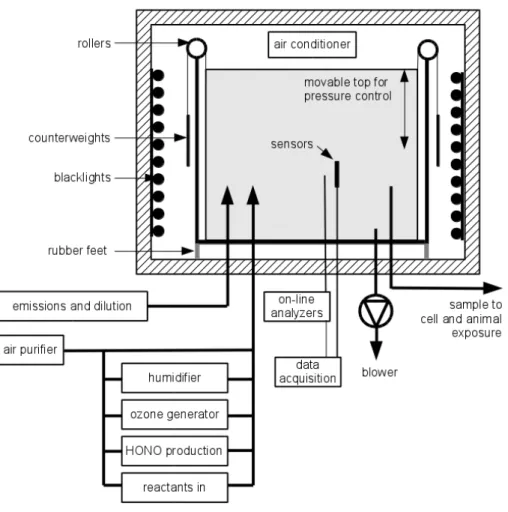
2.1 The environmental chamber
The chamber at Ilmari, sketched in Fig. 1, is manufactured by Foiltec GmbH, Germany, of a 125 µm thick fluorinated ethylene propylene resin (Teflon®FEP). Its shape is a rect-angular prism and it measures 3.5 m (length)×3.5 m (width)×2.4 m (height). Thus, its
5
nominal volume and surface area are, when full, 29.4 m3and 58.1 m2, respectively. The surface-to-volume ratio for a chamber is a parameter that describes, for example, the degree of wall effects. The higher the ratio, the more frequently the aerosol contacts the
walls. In prismatic or nearly cubical chambers, the surface-to-volume ratio is inversely proportional to its volume. For example, values of 3.0 in a 8 m3 chamber and of 1.4
10
in a 90 m3chamber have been reported (Platt et al., 2013; Carter et al., 2005). In our chamber the surface-to-volume ratio is 2.0, which equals to the surface-to-volume ratio of several other 27–30 m3 chambers (Wang et al., 2014; Paulsen et al., 2005; Cocker et al., 2001).
The chamber is a collapsible bag, which is attached to a moving top frame. There
15
are counterweights attached to the top frame by a steel wire, which goes over four low-friction rollers. The rollers are attached to the supporting frame around the chamber. All frames are made of an aluminium profile, whose cross section is 30 mm×30 mm. The
chamber is electrically insulated from the surroundings by letting the framework stand on rubber feet and by preventing the chamber walls from touching the surrounding
20
objects.
The pressure inside the chamber can be controlled by adding or removing extra weights on the moving top frame. In normal operation the combined weight of the chamber bag, the moving frame, and the extra weights is slightly more than that of the counterweights, so the top frame pushes the chamber bag and maintains an
over-25
AMTD
7, 5921–5951, 2014Characterization and testing of a new
environmental chamber
A. Leskinen et al.
Title Page
Abstract Introduction
Conclusions References
Tables Figures
◭ ◮
◭ ◮
Back Close
Full Screen / Esc
Printer-friendly Version Interactive Discussion
Discussion
P
a
per
|
Discus
sion
P
a
per
|
Discussion
P
a
per
|
Discussion
P
a
per
|
grid as the chamber is collapsed. The pressure difference between the chamber and
the surroundings (the experimental hall) is measured by a MicaFlex MF-PD pressure difference sensor (Mikor Instuments Ltd., Finland), whose operating range is from−50
to 50 Pa with an accuracy of±1.0 Pa.
The chamber is located in a thermally insulated enclosure, whose inner dimensions
5
are 4.3 m (width)×4.6 m (length)×3.1 m (height). Two arrays of blacklight lamps
(Syl-vania F36/T8 BLB 36 W) are placed between the enclosure wall and the chamber, on two opposite sides. There are altogether 160 lamps, which can be switched on in 18 dif-ferent combination, thereby enabling the adjustment of the output irradiance in almost a continuous manner. The inner walls of the enclosure are covered by aluminium plates
10
(floor) or foil (walls and ceiling) in order to enhance and equalize the UV radiation. The spectral irradiance inside the enclosure was measured with a portable spectrora-diometer (Optronic OL756), equipped with a dome window for semi-spatial irradiance measurements. The measured wavelength range was 250–800 nm with a bandwidth of 1 nm. The total irradiance was calculated by integrating the spectral irradiance over
15
the measured wavelength range.
The temperature of the enclosure is controlled by a thermostated air-conditioner (Argo AW 764 CL3), whose maximum cooling power is 6.5 kW. The desired tempera-ture can be preset in the range of 16–25◦C. The temperature in the chamber is mea-sured at nine points in order to monitor possible temperature gradients in the chamber.
20
In the middle of the chamber there is a combined temperature and humidity probe (Vaisala HMP 60;−40 to 60◦C and 0 to 100 %RH) and a diffusion type carbon dioxide
(CO2) sensor (Vaisala GMP 343; 0 to 1000 ppm). Near each corner (20 cm from the corner) there are altogether eight K-type thermocouples.
The inlet and outlet ports (Swagelok®) are attached to an aluminium plate (diameter
25
AMTD
7, 5921–5951, 2014Characterization and testing of a new
environmental chamber
A. Leskinen et al.
Title Page
Abstract Introduction
Conclusions References
Tables Figures
◭ ◮
◭ ◮
Back Close
Full Screen / Esc
Printer-friendly Version Interactive Discussion
Discussion
P
a
per
|
Discus
sion
P
a
per
|
Discussion
P
a
per
|
Discussion
P
a
per
separate lines. Maintenance work inside the chamber is possible when a 0.5 m×0.5 m
aluminium plate in the bottom face is removed.
The data from the sensors are acquired by National Instrument DAQ modules (NI9207 and NI9213) and transferred wirelessly to a PC, where they are stored in a database with a time resolution of 1 s by using a Datain data fusion system (Kuava
5
Ltd., Finland).
2.2 Characterization of the chamber
2.2.1 Aerosol wall losses
Ammoniumsulphate ((NH4)2SO4) particles were produced from a 1 g L− 1
solution of (NH4)2SO4 in water by using a constant output atomizer (TSI 3076), a silica gel diff u-10
sion dryer and a Kr-85 bipolar diffusion charger. The neutralized aerosol was injected
either directly into the chamber, filled with purified air, as a polydisperse sample (for 30 min at a flow rate of 3.0 L min−1) or through a size-selective differential mobility
anal-yser (TSI 3081 DMA) as monodisperse samples (for 2 h at the flow rate of 1.9 L min−1). The number median diameter and geometric standard deviation of the polydisperse
15
samples were 70 nm and 1.8, respectively, and the mobility equivalent diameters of the monodisperse samples were 50, 100, and 200 nm. It must be noted that a fraction of the particles exiting the DMA are larger than the selected size, possessing multi-ple elementary charges and therefore the same electrical mobility. The fraction of the multiply charged particles is estimated to be 4 % for the 50 nm, 14 % for the 100 nm,
20
and 27 % for the 200 nm monodisperse aerosol (Wiedensohler, 1988). The number of multiply charged particles were subtracted from the total number concentration of the monodisperse samples in the aerosol wall loss analysis.
The particle size distribution (14–750 nm) in the chamber was monitored, during the injection and the experiments that lasted 13–24 h, with a scanning mobility particle
25
AMTD
7, 5921–5951, 2014Characterization and testing of a new
environmental chamber
A. Leskinen et al.
Title Page
Abstract Introduction
Conclusions References
Tables Figures
◭ ◮
◭ ◮
Back Close
Full Screen / Esc
Printer-friendly Version Interactive Discussion
Discussion
P
a
per
|
Discus
sion
P
a
per
|
Discussion
P
a
per
|
Discussion
P
a
per
|
particle number concentration was obtained by integrating the size distribution over the particle size.
Provided that the aerosol in the chamber is well mixed, a coefficient for the wall loss
rate,βi (s−1), can be defined from (Crump et al., 1983)
dNi/dt=−βiNi, (1)
5
whereNi is the number concentration (cm−3) of particles of size classi in the
cham-ber. The coefficient β
i for each size class was obtained by integrating Eq. (1), which
gives−ln(Ni/Ni,0)=βit, and then by performing a linear fit to the data (t, ln(Ni/Ni,0)),
whereNi,0is the initial number concentration (cm− 3
) of size classi.
10
2.2.2 NO2photolysis rate
The photolysis rate of nitrogen dioxide (jNO2) was determined in order to characterise
the photochemical potential of the blacklights for the cases when 54 (1/3 of all), 108 (2/3 of all), or 160 (all) lamps were switched on. The NO2, NO, and O3concentrations
in the chamber were monitored with a trace-level chemiluminescence NO–NO2–NOx
15
analyser (Thermo 42i-TL) and an UV photometric ozone analyser (Thermo 49i). NO2
was injected from a gas cylinder into the chamber which had been flushed with puri-fied air, produced from indoor air with an oil-free compressor with a ballast tank and an air purifier with methane reactors (Model 737-250, Aadco Instruments Inc., USA). The system produces air with less than 1 ppb of ozone, methane, hydrocarbons, NO,
20
NOx, H2S, SO2, COS, CO, CO2, SF6 and fluorocarbons at the nominal flow rate of 250 L min−1. After 5 min for equilibration, all blacklights were switched on. The photol-ysis of NO2 leads to formation of NO and O3, which in turn react with each other and
produce NO2, and after some time, an equilibrium is established. The NO2 photolysis rate can be calculated from the equilibrium concentrations [NO] (ppb), [O3] (ppb), and 25
[NO2] (ppb) as
AMTD
7, 5921–5951, 2014Characterization and testing of a new
environmental chamber
A. Leskinen et al.
Title Page
Abstract Introduction
Conclusions References
Tables Figures
◭ ◮
◭ ◮
Back Close
Full Screen / Esc
Printer-friendly Version Interactive Discussion
Discussion
P
a
per
|
Discus
sion
P
a
per
|
Discussion
P
a
per
|
Discussion
P
a
per
wherek=1.8×10⁻¹⁴cm3molecule−1s−1is the rate constant of the reaction between
O3and NO at 298 K (Seinfeld and Pandis, 2006). Similar equilibria were sought for the
cases when only 2/3 or 1/3 of the lamps were switched on, in order to find out the effect
of irradiance on the NO2 photolysis rate. Since the equilibrium holds only in the
pres-ence of the UV lights, the gas concentrations start changing immediately when they
5
enter the dark sampling line to the gas analysers. In our case, the residence time be-tween the chamber and the analysers was 0.8 s, and therefore, the gas concentrations were corrected based on the reaction between O3and NO.
2.2.3 Inter-experiment cleaning of the chamber
The following procedure is used to clean the chamber between the experiments. First,
10
the aerosol from the chamber is sucked fast by the help of a blower until the cham-ber has collapsed (pressure difference−5 Pa). Then the chamber is filled with purified
and ozonised air with a high humidity (>90 %RH). The dry purified air was condi-tioned with a Model FC125-240-5MP-02 (Perma Pure LLC., USA) humidifier, where the humidity of the air flowing through is controlled by the temperature of the deionised
15
water on the other side of 240 pieces of Nafion® membrane tubes which allow water molecules to pass from the water stream into the air flow. During the filling stage of the chamber cleaning the water temperature in the humidifier was 35◦C. The ozone was generated by irradiating a part of the dry purified air with a high-energy UV lamp at 253 nm, filtered with a high-efficiency particulate absorption (HEPA) filter and mixed 20
with the humid air before transporting into the chamber. The temperature, relative hu-midity, overpressure, and ozone concentration in the chamber were monitored with the instruments described in Sects. 2.1 and 2.2.2, and necessary adjustments were made in order to keep the RH above 90 % and ozone concentration above 1 ppm. When the chamber reached its full volume, an outlet port was opened and all blacklight lamps
25
AMTD
7, 5921–5951, 2014Characterization and testing of a new
environmental chamber
A. Leskinen et al.
Title Page
Abstract Introduction
Conclusions References
Tables Figures
◭ ◮
◭ ◮
Back Close
Full Screen / Esc
Printer-friendly Version Interactive Discussion
Discussion
P
a
per
|
Discus
sion
P
a
per
|
Discussion
P
a
per
|
Discussion
P
a
per
|
all blacklights and ozone generation were switched offand the chamber was flushed
overnight with purified air, whose relative humidity was set to the value to be used in the next experiment. Before each experiment the purity of the chamber was tested by switching all blacklights on and monitoring the particle number concentration in the chamber with a condensation particle counter (TSI 3022A CPC). If the number
con-5
centration did not increase and stayed below 100 cm−3 for 20 min, the chamber was considered clean.
2.3 Test runs with toluene/O3/OH under the influence of UV
Four experiments with toluene (C7H8) in the presence of OH radicals and ozone and under the influence of the blacklights were carried out. First, ozone was injected into
10
the chamber (the ozone generation is described in Sect. 2.2.3) until a desired concen-tration was achieved. After a short stabilization time, HONO was produced by titrating sodiumnitrite (NaNO2) solution (1 wt-%) into sulphuric acid (H2SO4) solution (10
wt-%) in a glass flask equipped with a magnetic stirrer, based on the method developed by Taira and Kanda (1990). The gaseous HONO was carried by a purified air flow
15
of 3.0 L min−1 into the chamber. The HONO concentration, and the consequential OH concentration, in the chamber was adjusted by the amount of the NaNO2and the
injec-tion time. The mixing of HONO was monitored from the NO2 concentration calculated by the NO–NOx analyser as the difference between NOx and NO concentrations,
be-cause the instrument reduces HONO to NO in a similar manner to the conversion of
20
NO2 (Taira and Kanda, 1990). The titration also produces NO and NO2, whose con-centrations depend on the carrier gas flow rate. At the flow rate of 3.0 L min−1 in our experiments, however, the fractions of NO and NO2can be considered negligible (Taira
and Kanda, 1990).
When the HONO concentration in the chamber had stabilized, liquid toluene
(Sigma-25
Aldrich,>99.9 %) was injected with a syringe through a septum into a 6 mm stainless steel tube where it mixed with purified air, flowing into the chamber at the flow rate of 100 L min−1
AMTD
7, 5921–5951, 2014Characterization and testing of a new
environmental chamber
A. Leskinen et al.
Title Page
Abstract Introduction
Conclusions References
Tables Figures
◭ ◮
◭ ◮
Back Close
Full Screen / Esc
Printer-friendly Version Interactive Discussion
Discussion
P
a
per
|
Discus
sion
P
a
per
|
Discussion
P
a
per
|
Discussion
P
a
per
The toluene concentration and the oxidation products in the chamber were monitored using a high-resolution proton transfer reaction mass spectrometer (PTR-TOF 8000, Ionicon Analytik, Innsbruck, Austria). Sample air from the chamber stainless steel inlet port was introduced to the PTR drift tube via a 1.5 m long heated (60◦C) PEEK tubing (inner diameter 1 mm) at a flow rate of 160 mL min−1. PTR-MS was operated under
5
controlled conditions (2.3 mbar drift tube pressure, 600 V drift tube voltage and 60◦C temperature). The raw PTR-MS data were post-processed by PTR-MS Viewer 3.1.0.18 program (Ionicon Analytic). Concentrations in parts per billion (ppb) were calculated by the program using a standard reaction rate constant of 2×10⁻⁹cm3molecule−1s−1.
After stabilization and mixing of the components, the blacklights were switched on.
10
During the irradiation HONO efficiently photolyzes to form OH and NO. The initial OH
radical concentration was estimated from the first-order decay of toluene observed in the PTR-MS. A reaction rate constant of 5.6×10⁻¹²cm3molecule−1s−1 was used
for the OH-toluene reaction (Calvert et al., 2002). It must be noted that OH radical formation through the HONO photochemistry produces easily a high concentration of
15
NO, which is known to suppress SOA formation (Ng et al., 2007). If the presence of NO needs to be avoided, a different generation method for OH radicals, such as the
photochemical decomposition of hydrogen peroxide (H2O2), should be used.
The concentration of selected reaction products of toluene with OH were monitored with the PTR-MS. The selected reaction products were CH3O
+
(m/z31.018), C2H5O + 20
(m/z45.034), C3H7O+ (m/z59.049), C3H5O+2 (m/z 73.029), C4H5O+2 (m/z85.029), C4H3O
+
3 (m/z99.008), C5H7O +
2 (m/z 99.044), C7H7O +
(m/z107.049) and C7H9O +
(m/z 109.065). They were selected based on toluene photooxidation reactions pro-vided by the Master Chemical Mechanism (MCM) model (Wagner et al., 2003; Gómes Alvarez et al., 2007). Molar yields of gas phase oxidation products were calculated as
25
AMTD
7, 5921–5951, 2014Characterization and testing of a new
environmental chamber
A. Leskinen et al.
Title Page
Abstract Introduction
Conclusions References
Tables Figures
◭ ◮
◭ ◮
Back Close
Full Screen / Esc
Printer-friendly Version Interactive Discussion
Discussion
P
a
per
|
Discus
sion
P
a
per
|
Discussion
P
a
per
|
Discussion
P
a
per
|
The SOA yield,Y, was calculated as the ratio of the formed mass,∆Mo(µg m−3), to
the reacted toluene (a volatile organic compound, VOC) mass,∆VOC (µg m−3), in the
course of the experiment, as
Y = ∆Mo/∆VOC. (3)
5
The formed mass was estimated from the wall loss corrected total aerosol volume, calculated from the SMPS data, and by assuming a density of 1400 kg m−3 for the produced SOA (Ng et al., 2007).
3 Results
3.1 Particle wall loss rates
10
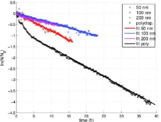
The particle wall loss rate constantsβin Eq. (1) for 50, 100, and 200 nm monodisperse particles with an initial number concentration of 1690, 840, and 340 cm−3, were 0.080, 0.045, and 0.040 h−1, respectively (Fig. 2). These wall loss rates are only 18–33 % of
those observed by Wang et al. (2014) in a 30 m3 chamber. One possible reason for the difference is that the chamber in Ilmari has no mixing fans which could enhance 15
the wall deposition by increasing turbulence inside the chamber. Furthermore, Wang et al. used excerpts of polydisperse aerosol, while our rates were determined for almost pure monodisperse aerosol (including up to 27 % of larger, multiply charged particles), for which the coagulation rate is smaller than for polydisperse aerosols with the same number concentration (e.g., Seinfeld and Pandis, 2006). Also, at the number
concen-20
trations in our experiments the effect of coagulation is only minor or negligible at the
time scales of our experiments (maximum duration 40 h), as discussed, e.g., by Cocker et al. (2001).
The wall loss rate for polydisperse aerosol was faster in the beginning and levelled offto 0.088 h−1in 10 h (Fig. 2). In the beginning of the experiment the particle number 25
concentration was 12 700 cm−3
AMTD
7, 5921–5951, 2014Characterization and testing of a new
environmental chamber
A. Leskinen et al.
Title Page
Abstract Introduction
Conclusions References
Tables Figures
◭ ◮
◭ ◮
Back Close
Full Screen / Esc
Printer-friendly Version Interactive Discussion
Discussion
P
a
per
|
Discus
sion
P
a
per
|
Discussion
P
a
per
|
Discussion
P
a
per
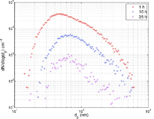
number concentration. Also, smaller particles deposit faster onto the chamber walls. Figure 3 illustrates these effects: the median of the particle size increases from the
initial 50 nm to 65 nm in 10 h. After this, no growth of particles but only decrease in concentration is observed.
The polydisperse aerosol number loss rate in our chamber is comparable to those
5
in, e.g., the Guangzhou (30 m3), PSI (27 m3), and the California Institute of Technology (28 m3) chambers with loss rates of 0.17 h−1, 0.209±0.018 h−1, and 0.09–0.18 h−1,
respectively (Wang et al., 2014; Paulsen et al., 2005; Cocker et al., 2001). The particle half-life in our chamber is 8–17 h, which is remarkably longer than, e.g., the 2.8±0.8 h
in the PSI mobile chamber (Platt et al., 2013). The longer half-life arises from a smaller
10
surface-to-volume ratio, which is 2.0 m−1
in our chamber, as compared to 3.0 m−1
in the PSI mobile chamber. Also, as it can be seen in our measurements, the loss rate is highly dependent on particle size, and the overall decrease rate of the total number concentration depends on the size distribution of the inspected aerosol, which makes an exact comparison difficult.
15
3.2 Blacklight lamps and NO2photolysis rate
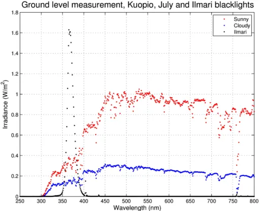
The blacklight lamps irradiate a spectrum that is centered at 365 nm with a half-width of 16 nm (Fig. 4). The spectrum is skewed to the longer wavelengths because of cut-ting the deeper ultraviolet radiation due to safety regulations for the lamps, which are originally intended for use in public areas, like discotheques. However, the irradiation is
20
in the range for many important photochemical reactions, such as NO2 photolysis and OH radical formation from HONO (Seinfeld and Pandis, 2006).
The integral irradiances at the UV region (λ <400 nm) with the set of 1/3, 2/3, and all blacklights switched on were 9.8, 14.7, and 29.7 W m−2
, respectively. The maximum and 1/3 UV irradiances correspond approximately the UV irradiances of 24.8 W m−2
25
AMTD
7, 5921–5951, 2014Characterization and testing of a new
environmental chamber
A. Leskinen et al.
Title Page
Abstract Introduction
Conclusions References
Tables Figures
◭ ◮
◭ ◮
Back Close
Full Screen / Esc
Printer-friendly Version Interactive Discussion
Discussion
P
a
per
|
Discus
sion
P
a
per
|
Discussion
P
a
per
|
Discussion
P
a
per
|
The NO2 photolysis rate (Eq. 2), at these irradiances were 0.0037, 0.0058, and 0.0103 s−1
(or 0.22, 0.35, and 0.62 min−1
or 13.2, 20.8, and 37.1 h−1
), respectively. The correction due to dark reactions of ozone and NO in the sampling line was less than 1.4 % for each compound and irradiance. The maximum NO2photolysis rate in our
chamber is comparable to those reported in other indoor photoreactors, such as the
5
rate of 0.12 min−1 in the 27 m3 chamber at the Paul Scherrer Institute (Paulsen et al., 2005), 0.19 min−1in the 90 m3 environmental chamber at the University of California, Riverside (Carter et al., 2005), 1.5 min−1in the 28 m3chamber at the California Institute
of Technology (Cocker et al., 2001), and 8.0±0.7×10⁻³s−1in the mobile environmental
chamber of the PSI (Platt et al., 2013).
10
3.3 Temperature control and distribution
The air conditioning is capable of keeping the temperature below 25◦C and within 1◦C
when at most half of the blacklights are on. With more lights on, the current cooling capacity is nor sufficient and the temperature inside the chamber may rise
signifi-cantly. This is important because the equilibria of the semivolatile species between
15
the gas and particle phase are usually exponentially temperature-dependent. Further-more, condensation in the sampling lines is possible when a warmer sample enters colder sampling lines, at least in experiments with a high relative humidity in the cham-ber.
The temperature inside the chamber was quite uniformly distributed. When the lights
20
were off, the temperatures in each corner were within 0.5◦C. The difference was greater
when the lights were on, being 0.9◦C at maximum. The differences are unlikely to
cause, e.g., thermal diffusion into a certain direction, or thermophoretic effects.
3.4 Toluene experiments
The initial concentrations of ozone, HONO, toluene, and NOx in the chamber in each
25
AMTD
7, 5921–5951, 2014Characterization and testing of a new
environmental chamber
A. Leskinen et al.
Title Page
Abstract Introduction
Conclusions References
Tables Figures
◭ ◮
◭ ◮
Back Close
Full Screen / Esc
Printer-friendly Version Interactive Discussion
Discussion
P
a
per
|
Discus
sion
P
a
per
|
Discussion
P
a
per
|
Discussion
P
a
per
injected HONO, because both NO and NO2concentration were less than 0.6 ppb be-fore HONO injection in each experiment.
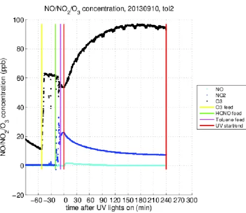
After switching the blacklights on the NO from the decomposition of HONO was converted rapidly into NO2 because there was always ozone present in the chamber. The NO2 decomposed into NO and O, which, in turn, produced ozone. There was 5
a net production of ozone, and the ozone was seen to accumulate into the chamber. For example, the maximum ozone concentration was 95 ppb in experiment T130910 (Fig. 5).
The SOA volume (and mass) increased under the influence of UV radiation (Fig. 6). Since no seed aerosol was used, the SOA particles were not detected until they had
10
grown larger than 14 nm, the lower detection limit of the SMPS, approximately 10 min after the lights had been switched on. Over time, the SOA volume concentrations lev-elled off and reached 12.5, 10.8, and 5.0 µm3cm−3 in 295, 195, and 93 min in the
experiments T130910, T130911, and T130912, respectively. The corresponding SOA mass concentration and toluene consumption, and the SOA yield, calculated by using
15
Eq. (3), are given in Table 2.
The SOA yields (0.33–0.44; Table 2) were 7–48 % higher than those obtained by Ng et al. (2007) in the seeded, low-NOx experiments, even though SOA yield is known
to be lower without seed particles (Kroll et al., 2007) and NOx is known to suppress
SOA formation (Ng et al., 2007). Furthermore, in our experiments thek in Eq. (2) was
20
0.31 min−1, which is approximately 40 % of that in the experiments by Ng et al. (2007, k=0.75 min−1), and hence the yield should be lower because of its proportional
de-pendence on the light intensity (Warren et al., 2008). Huang et al. (2013) obtained a SOA yield of approximately 0.1 when no seed particles were present and 0.2–0.4 when seed particles were present, depending on the seed particle material. It must be
25
AMTD
7, 5921–5951, 2014Characterization and testing of a new
environmental chamber
A. Leskinen et al.
Title Page
Abstract Introduction
Conclusions References
Tables Figures
◭ ◮
◭ ◮
Back Close
Full Screen / Esc
Printer-friendly Version Interactive Discussion
Discussion
P
a
per
|
Discus
sion
P
a
per
|
Discussion
P
a
per
|
Discussion
P
a
per
|
Burtscher, 2012). Also, a part of the vapors are lost to the chamber walls, which is more intense in the absence of seed particles (Zhang et al., 2014; Kokkola et al., 2014).
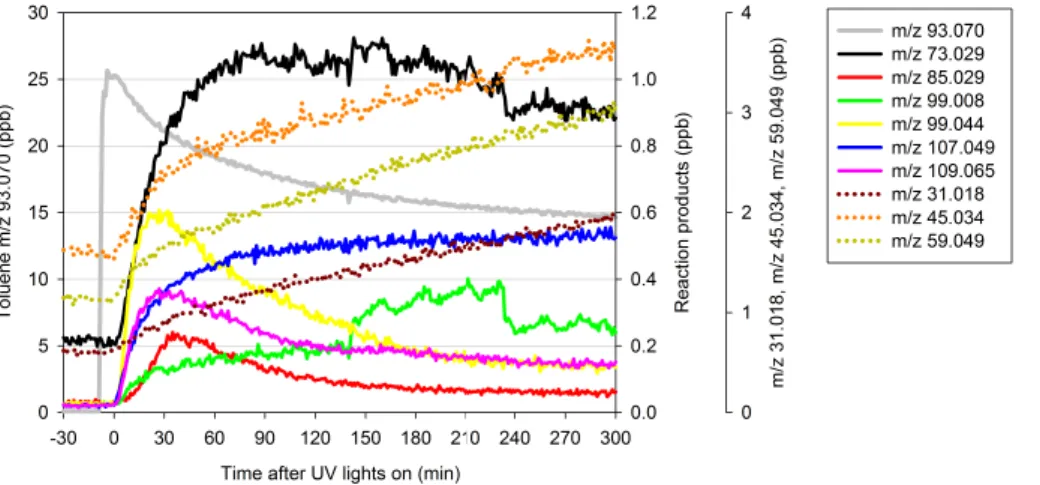
A time series of selected product ion concentrations in experiment T130910 is il-lustrated in Fig. 7, where the typical first generation oxidation products with m/z of 73.029 (e.g. methylglyoxal), 85.029 (e.g. 2-butenedial), 99.044 (e.g. 4-oxo-2-pentenal),
5
107.049 (e.g. benzaldehyde), and 109.065 (e.g. cresol) can be distinguished from the rapid increase in the beginning and a decrease after their consumption exceeds their production (peak concentration at approximately 30 min). The concentration of the sec-ond generation oxidation products with m/z of 31.018 (formaldehyde), 45.034 (ac-etaldehyde), 59.049 (acetone), and 99.008 (e.g. 2,5-furandione) increases slowly and
10
is still increasing after 300 min of UV exposure. The formation mechanism of these OH initiated oxidation products of toluene have been discussed in earlier studies (Forstner et al., 1997; Wagner et al., 2003; Gómes Alvarez et al., 2007). Glyoxal (m/z 59.013) has also been confirmed as one of the main photooxidation products of toluene (e.g. Smith et al., 1998). We could not distinguish glyoxal in the current study with
PTR-15
MS because the signal interfered with near acetone peak (m/z59.049). However, due to the high sensitivity of PTR-MS we were able to detect traces of nitro compounds which were formed during the further oxidation reactions with OH and NO2. For
exam-ple, after 30 min of UV exposure traces of possible secondary oxidation productsm/z 154.05 (C7H8NO+3) were detected. The compound was tentatively identified as methyl
20
nitrophenol.
The yields for the selected gas phase oxidation products in the experiments T130909–130911 are given in Table 3. The variation in the yields might be explained by differences between the initial conditions of the chamber experiments. Similar to other
studies (Smith et al., 1998; Gómes Alvarez et al., 2007), the highest formation yields
25
AMTD
7, 5921–5951, 2014Characterization and testing of a new
environmental chamber
A. Leskinen et al.
Title Page
Abstract Introduction
Conclusions References
Tables Figures
◭ ◮
◭ ◮
Back Close
Full Screen / Esc
Printer-friendly Version Interactive Discussion
Discussion
P
a
per
|
Discus
sion
P
a
per
|
Discussion
P
a
per
|
Discussion
P
a
per
were observed. Gómes Alvarez et al. (2007) measured a yield of 13 % for 2-butenedial, which is comparable to that for the ion withm/zof 85.029 (4.1–7.6 %) in our measure-ments. Smith et al. (1998) reported similar yield for benzaldehyde, but a twice lower yield for cresol with 6 % and 17.9 %, respectively.
The oxidation products of toluene can be found in both gaseous and particulate
5
phases, as reported by earlier research (Forstner et al., 1997; Sato et al., 2007; White et al., 2014). Our analysis did not include a detailed chemical analysis of the particulate phase, and therefore the yields in Table 3 can be underestimations.
4 Conclusions
The functionality of the new environmental chamber at the Ilmari research facility was
10
tested for secondary product formation both in particle and gas phase. The observed yields of SOA and gaseous first and second generation reaction products were reason-able and comparreason-able to those obtained in other laboratories. However, direct compar-ison is complicated, because the yields depend greatly on conditions and initial con-centrations. For quantitative verification of the yields, calculations with a photooxidation
15
reaction model, such as the MCM, would be needed.
The wall loss rates of aerosol particles on the chamber walls are small enough, be-cause of the low surface-to-volume ratio, to enable experiments with duration of several hours. The particle half-life in the chamber at Ilmari is comparable or somewhat longer than those in other laboratories. The movable top of the chamber enables maintaining
20
an overpressure in the chamber during the experiments, which prevents dilution of the sample in the chamber and contaminants from entering the chamber.
The conditions in the chamber can be kept constant with the current setup when half of the available lights are used. One of the next steps in developing the chamber facility is to increase the cooling power of the air conditioner in order to keep the temperature
25
AMTD
7, 5921–5951, 2014Characterization and testing of a new
environmental chamber
A. Leskinen et al.
Title Page
Abstract Introduction
Conclusions References
Tables Figures
◭ ◮
◭ ◮
Back Close
Full Screen / Esc
Printer-friendly Version Interactive Discussion
Discussion
P
a
per
|
Discus
sion
P
a
per
|
Discussion
P
a
per
|
Discussion
P
a
per
|
Acknowledgements. The infrastructure has been supported financially by the European Re-gional Development Fund (ERDF), the Finnish Funding Agency for Technology and Innovation (Tekes), and the strategic funding of University of Eastern Finland (Sustainable Bioenergy, Cli-mate Change and Health). The work of Pasi Yli-Pirilä was financially supported by the Academy of Finland (decision no. 252908).
5
References
Calvert, J. G., Atkinson, R., Becker, K. H., Kamens, R. M., Seinfeld, J. H.,Wallington, T. J., and Yarwoord, G.: The Mechanisms of Atmospheric Oxidation of Aromatic Hydrocarbons, Oxford University Press, New York, 556 pp., 2002.
Carter, W. P. L., Cocker, D. R. III, Fitz, D. R., Malkina, I. L., Bumiller, K., Sauer, C. G.,
10
Pisano, J. T., Bufalino, C., and Song, C.: A new environmental chamber for evaluation of gas-phase chemical mechanisms and secondary aerosol formation, Atmos. Environ., 39, 7768–7788, doi:10.1016/j.atmosenv.2005.08.040, 2005.
Cocker III, D. R., Flagan, R. C., and Seinfeld, J. H.: State-of-the-art chamber facility for studying atmospheric aerosol chemistry, Environ. Sci. Technol., 35, 2594–2601, 2001.
15
Crump, J. G., Flagan, R. C., and Seinfeld, J. H.: Particle wall loss rates in vessels, Aerosol Sci. Tech., 2, 303–309, 1983.
Forstner, H. J., Flagan, R. C., and Seinfeld, J. H.: Secondary organic aerosol from the photoox-idation of aromatic hydrocarbons: molecular composition, Environ. Sci. Technol., 31, 1345– 1358, 1997.
20
Gómes Alvarez, E., Viidanoja, J., Muños, A., Wirtz, K., and Hjorth, J.: Experimental confirmation of the dicarbonyl route in the photo-oxidation of toluene and benzene, Environ. Sci. Technol., 41, 8362–8369, 2007.
Hallquist, M., Wenger, J. C., Baltensperger, U., Rudich, Y., Simpson, D., Claeys, M., Dom-men, J., Donahue, N. M., George, C., Goldstein, A. H., Hamilton, J. F., Herrmann, H., Hoff -25
sec-AMTD
7, 5921–5951, 2014Characterization and testing of a new
environmental chamber
A. Leskinen et al.
Title Page
Abstract Introduction
Conclusions References
Tables Figures
◭ ◮
◭ ◮
Back Close
Full Screen / Esc
Printer-friendly Version Interactive Discussion
Discussion
P
a
per
|
Discus
sion
P
a
per
|
Discussion
P
a
per
|
Discussion
P
a
per
ondary organic aerosol: current and emerging issues, Atmos. Chem. Phys., 9, 5155–5236, doi:10.5194/acp-9-5155-2009, 2009.
Huang, M., Hao, L., Gu, X., Hu, C., Zhao, W., Wang, Z., Fang, L., and Zhang, W.: Effects
of inorganic seed aerosols on the growth and chemical composition of secondary organic aerosol formed from OH-initiated oxidation of toluene, J. Atmos. Chem., 70, 151–164,
5
doi:10.1007/s10874-013-9262-9, 2013.
Keller, A. and Burtscher, H.: A continuous photo-oxidation flow reactor for a defined measure-ment of the SOA formation potential of wood burning emissions, J. Aerosol Sci., 49, 9–20, doi:10.1016/j.jaerosci.2012.02.007, 2012.
Kokkola, H., Yli-Pirilä, P., Vesterinen, M., Korhonen, H., Keskinen, H., Romakkaniemi, S.,
10
Hao, L., Kortelainen, A., Joutsensaari, J., Worsnop, D. R., Virtanen, A., and Lehtinen, K. E. J.: The role of low volatile organics on secondary organic aerosol formation, Atmos. Chem. Phys., 14, 1689–1700, doi:10.5194/acp-14-1689-2014, 2014.
Kroll, J. H., Chan, A. W. H., Ng, N. L., Flagan, R. C., and Seinfeld, J. H.: Reactions of semivolatile organics and their effects on secondary organic aerosol formation, Environ. Sci. 15
Technol., 41, 3545–3550, doi:10.1021/es062059x, 2007.
Lambe, A. T., Ahern, A. T., Williams, L. R., Slowik, J. G., Wong, J. P. S., Abbatt, J. P. D., Brune, W. H., Ng, N. L., Wright, J. P., Croasdale, D. R., Worsnop, D. R., Davidovits, P., and Onasch, T. B.: Characterization of aerosol photooxidation flow reactors: heterogeneous oxidation, secondary organic aerosol formation and cloud condensation nuclei activity
mea-20
surements, Atmos. Meas. Tech., 4, 445–461, doi:10.5194/amt-4-445-2011, 2011.
McMurry, P. H. and Grosjean, D.: Gas and aerosol wall losses in teflon film smog chambers, Environ. Sci. Technol., 19, 1176–1182, 1985.
Ng, N. L., Kroll, J. H., Chan, A. W. H., Chhabra, P. S., Flagan, R. C., and Seinfeld, J. H.: Secondary organic aerosol formation fromm-xylene, toluene, and benzene, Atmos. Chem.
25
Phys., 7, 3909–3922, doi:10.5194/acp-7-3909-2007, 2007.
Paulsen, D., Dommen, J., Kalberer, M., Prévôt, A. S. H., Richter, R., Sax, M., Steinbachner, M., Weingartner, E., and Baltensperger, U.: Secondary organic aerosol formation by irradiation of 1,3,5-trimethylbenzene–NOx–H2O in a new reaction chamber for atmospheric chemistry and physics, Environ. Sci. Technol., 39, 2668–2678, 2005.
30
Platt, S. M., El Haddad, I., Zardini, A. A., Clairotte, M., Astorga, C., Wolf, R., Slowik, J. G., Temime-Roussel, B., Marchand, N., Ježek, I., Drinovec, L., Močnik, G., Möhler, O.,
or-AMTD
7, 5921–5951, 2014Characterization and testing of a new
environmental chamber
A. Leskinen et al.
Title Page
Abstract Introduction
Conclusions References
Tables Figures
◭ ◮
◭ ◮
Back Close
Full Screen / Esc
Printer-friendly Version Interactive Discussion
Discussion
P
a
per
|
Discus
sion
P
a
per
|
Discussion
P
a
per
|
Discussion
P
a
per
|
ganic aerosol formation from gasoline vehicle emissions in a new mobile environmental reac-tion chamber, Atmos. Chem. Phys., 13, 9141–9158, doi:10.5194/acp-13-9141-2013, 2013. Sato, K., Hatakeyama, S., and Imamura, T.: Secondary organic aerosol formation during the
photooxidation of toluene: NOx dependence of chemical composition, J. Phys. Chem. A, 111, 9796–9808, 2007.
5
Seinfeld, J. H. and Pandis, S. N. (Eds.): Atmospheric Chemistry and Physics, Wiley, New York, 204–283, 2006.
Smith, D. F., McIver, C. D., and Kleindienst, T. E.: Primary product distribution from the reaction of hydroxyl radicals with toluene at ppb NOx mixing ratios, J. Atmos. Chem., 30, 209–228, 1998.
10
Taira, M. and Kanda, Y.: Continuous generation system for low-concentration gaseous nitrous acid, Anal. Chem., 62, 630–633, 1990.
Wagner, V., Jenkin, M. E., Saunders, S. M., Stanton, J., Wirtz, K, and Pilling, M. J.: Modelling of the photooxidation of toluene: conceptual ideas for validating detailed mechanisms, Atmos. Chem. Phys., 3, 89–106, doi:10.5194/acp-3-89-2003, 2003.
15
Wang, X., Liu, T., Bernard, F., Ding, X., Wen, S., Zhang, Y., Zhang, Z., He, Q., Lü, S., Chen, J., Saunders, S., and Yu, J.: Design and characterization of a smog chamber for studying gas-phase chemical mechanisms and aerosol formation, Atmos. Meas. Tech., 7, 301–313, doi:10.5194/amt-7-301-2014, 2014.
Warren, B., Song, C., and Cocker, D. R. III: Light intensity and light source influence on
sec-20
ondary organic aerosol formation for them-xylene/NOxphotooxidation system, Environ. Sci. Technol., 42, 5461–5466, doi:10.1021/es702985n, 2008.
White, S. J., Jamie, I. M., and Angove, D. E.: Chemical characterisation of semi-volatile and aerosol compounds from the photooxidation of toluene and NOx, Atmos. Environ., 83, 237– 244, doi:10.1016/j.atmosenv.2013.11.023, 2014.
25
Wiedensohler, A.: An approximation of the bipolar charge distribution for particles in the submi-cron size range, J. Aerosol Sci., 19, 387–389, 1988.
Zhang, X., Cappa, C. D., Jathar, S. H., McVay, R. C., Ensberg, J. J., Kleeman, M. J., and Seinfeld, J. H.: Influence of vapor wall loss in laboratory chambers on yields of secondary organic aerosol, Proc. Natl. Acad. Sci., published ahead of print 7 April 2014, 111, 1–6,
30
doi:10.1073/pnas.1404727111, 2014.
AMTD
7, 5921–5951, 2014Characterization and testing of a new
environmental chamber
A. Leskinen et al.
Title Page
Abstract Introduction
Conclusions References
Tables Figures
◭ ◮
◭ ◮
Back Close
Full Screen / Esc
Printer-friendly Version Interactive Discussion
Discussion
P
a
per
|
Discus
sion
P
a
per
|
Discussion
P
a
per
|
Discussion
P
a
per
and xylenes in an atmospheric urban hydrocarbon mixture: water and particle seed effects
(II), Atmos. Environ., 45, 3882–3890, doi:10.1016/j.atmosenv.2010.12.048, 2011.
AMTD
7, 5921–5951, 2014Characterization and testing of a new
environmental chamber
A. Leskinen et al.
Title Page
Abstract Introduction
Conclusions References
Tables Figures
◭ ◮
◭ ◮
Back Close
Full Screen / Esc
Printer-friendly Version Interactive Discussion
Discussion
P
a
per
|
Discus
sion
P
a
per
|
Discussion
P
a
per
|
Discussion
P
a
per
|
Table 1.Initial concentrations and conditions in the test runs with toluene. [NO2]HONO is the apparent NO2 concentration calculated by the analyzer after HONO injection.N is the initial particle number concentration.
Run [O3] (ppb) [NO2]HONO(ppb) [Toluene] (ppb) [NOx] (ppb) [OH]×107(cm−3) T (◦C) RH (%) N(cm−3)
T130909 48.5 18.8 24.7 19.1 2.3 22.2 54.0 N/A
T130910 53.8 20.1 25.3 22.4 2.1 20.4 65.0 56
T130911 55.2 12.6 26.2 11.9 1.5 22.6 67.9 44
AMTD
7, 5921–5951, 2014Characterization and testing of a new
environmental chamber
A. Leskinen et al.
Title Page
Abstract Introduction
Conclusions References
Tables Figures
◭ ◮
◭ ◮
Back Close
Full Screen / Esc
Printer-friendly Version Interactive Discussion
Discussion
P
a
per
|
Discus
sion
P
a
per
|
Discussion
P
a
per
|
Discussion
P
a
per
Table 2.Formed SOA mass (∆M
o), reacted toluene mass (∆VOC) and SOA yield (Y) in the
test runs with toluene.
Run ∆M
o(µg m
−3
) ∆VOC (µg m−3
) Y
AMTD
7, 5921–5951, 2014Characterization and testing of a new
environmental chamber
A. Leskinen et al.
Title Page
Abstract Introduction
Conclusions References
Tables Figures
◭ ◮
◭ ◮
Back Close
Full Screen / Esc
Printer-friendly Version Interactive Discussion
Discussion
P
a
per
|
Discus
sion
P
a
per
|
Discussion
P
a
per
|
Discussion
P
a
per
|
Table 3.Gas phase oxidation product yields from oxidation of toluene on percent basis.
Run m/z31.018 m/z45.034 m/z59.049 m/z73.029 m/z85.029 m/z99.008 m/z99.044 m/z107.049 m/z109.065
T130909 5.5 14.6 11.8 5.3 0.5 1.3 9.5 7.5 7.2
T130910 6.4 18.3 11.3 15.4 4.1 2.7 14.4 7.8 8.6
T130911 5.9 22.5 13.7 19.5 7.6 7.6 19.5 8.4 9.3
AMTD
7, 5921–5951, 2014Characterization and testing of a new
environmental chamber
A. Leskinen et al.
Title Page
Abstract Introduction
Conclusions References
Tables Figures
◭ ◮
◭ ◮
Back Close
Full Screen / Esc
Printer-friendly Version Interactive Discussion
Discussion
P
a
per
|
Discus
sion
P
a
per
|
Discussion
P
a
per
|
Discussion
P
a
per
|
Figure 2.The logarithmic relative number concentration as a function of time of 50, 100, and 200 nm monodisperse and polydisperse ammoniumsulphate aerosols. The equations for the linear fittings are ln(N/N0)=−0.0803t+0.0078 (50 nm), ln(N/N
0)=−0.0445t+0.0128 (100 nm),
ln(N/N0)=−0.0403t−0.0722 (200 nm), and ln(N/N
0)=−0.0875t+0.8878 (polydisperse, after
AMTD
7, 5921–5951, 2014Characterization and testing of a new
environmental chamber
A. Leskinen et al.
Title Page
Abstract Introduction
Conclusions References
Tables Figures
◭ ◮
◭ ◮
Back Close
Full Screen / Esc
Printer-friendly Version Interactive Discussion
Discussion
P
a
per
|
Discus
sion
P
a
per
|
Discussion
P
a
per
|
Discussion
P
a
per
|
AMTD
7, 5921–5951, 2014Characterization and testing of a new
environmental chamber
A. Leskinen et al.
Title Page
Abstract Introduction
Conclusions References
Tables Figures
◭ ◮
◭ ◮
Back Close
Full Screen / Esc
Printer-friendly Version Interactive Discussion
Discussion
P
a
per
|
Discus
sion
P
a
per
|
Discussion
P
a
per
|
Discussion
P
a
per
|
AMTD
7, 5921–5951, 2014Characterization and testing of a new
environmental chamber
A. Leskinen et al.
Title Page
Abstract Introduction
Conclusions References
Tables Figures
◭ ◮
◭ ◮
Back Close
Full Screen / Esc
Printer-friendly Version Interactive Discussion
Discussion
P
a
per
|
Discus
sion
P
a
per
|
Discussion
P
a
per
|
Discussion
P
a
per
Figure 7. The evolution of the concentrations of toluene (m/z 93.070) and selected oxida-tion products in the chamber in the experiment T130910. Tentatively identified oxidaoxida-tion prod-ucts:m/z73.029 (methyl glyoxal),m/z85.029 (2-butenedial),m/z99.044 (4-oxo-2-pentenal),
![Table 1. Initial concentrations and conditions in the test runs with toluene. [NO 2 ] HONO is the apparent NO 2 concentration calculated by the analyzer after HONO injection](https://thumb-eu.123doks.com/thumbv2/123dok_br/18426485.361611/22.918.38.687.325.407/initial-concentrations-conditions-apparent-concentration-calculated-analyzer-injection.webp)