ABSTRACT: This paper aims to present the Comprehensiveness Balance for Eficiency (CBfE) method for Platform-Based Satellite Family. The lack of a penalty measurement to assess the performance loss of using a platform could reduce signiicantly the family performance. The method, taking into account the comprehensiveness of space missions and the platform characteristics deined at the conception phase, assesses the platform ineficiency, in terms of the additional mass required by the platform equipment to cope with the worst environment factors. The method covers the aerodynamic drag and torque, the Earth’s magnetic ield, the eclipse and Sun energy absorption, the cumulated radiation dose absorbed by the electronic components and the effect on the structure to be prepared for several launchers. Based on this assessment and on an interactive process, the platform designer tunes the comprehensiveness with the suitable level of eficiency. A real case, the Brazilian MultiMission Platform project (PMM), is presented as an example of application. The method covers an existing gap on the platform development process for space applications.
KEYWORDS: Platform, Product family, Satellite family, Development process, Platform eficiency.
Eficiency-Multimission Comprehensiveness
Balance for Platform-Based Satellite Family
Otavio Luiz Bogossian1, Geilson Loureiro1, Roberto Vieira Fonseca Lopes1, Edgardo Roggero2INTRODUCTION
The family of products concept became relevant with the transformation of the mass production concept into mass customization aiming to comply with individual client needs (Pine, 1993). he family is a set of similar products obtained from a common platform, given to each product the functionalities required by speciic clients (Meyer and Lehnerd, 1997). A product platform is a set of subsystems and interfaces developed to form a common structure (or core) from which a stream of derivative products can be eiciently developed and produced (Meyer and Lehnerd, 1997). Several authors have been working on deining a family of products and the corresponding platform for general applications. he segmentation market grid based on platform was introduced as the way to leverage the family of products across diferent market niches (Meyer and Lehnerd, 1997). Meyer and Utterback (1993) attempt to map the evolution of a given product family based on platform by means of extensions and upgrades. Bogossian and Loureiro (2011) grouped the family deinition in three classes: based on design methods (modularity, platform based, conigurational or scalable), based on generation of product variety to target market niches and based on technical aspects for improving the product process, stock reduction and component reutilization promotion.
SpACE COnTExT
he space context has speciic characteristics such as the complexity of the products and the very low production volume. It was remarked that space products are designed to comply with a particular mission (Gonzalez-Zugasti et al., 2000). he space product (the spacecrat) is designed for its particular mission (independent development). his contrasts with products for general applications in which they are designed for a niche market.
1.Instituto Nacional de Pesquisas Espacias – São José dos Campos/SP – Brazil 2.Comisión Nacional de Actividades Espaciales – Buenos Aires – Argentina
Author for correspondence: Otavio Luiz Bogossian | Instituto Nacional de Pesquisas Espaciais | Avenida dos Astronautas, 1.758 – Jardim da Granja | CEP 12.227-010 São José dos Campos/SP – Brazil | Email: [email protected]
A preliminary question stated during the development process is the possibility to deine a satellite family and its platform (the common core), taking into account that each mission has speciic objective and environment. Based on these speciicities, it seems preliminary that the platform will pay a signiicant penalty.
his paper aimed to present and justify the elements of a method named Comprehensiveness Balance for Eiciency (CBfE) to conceive a low Earth orbit satellite family with the scope deined in terms of mission attributes like orbits, wings number and pointing (mission comprehensiveness) and the platform characteristics to cope with the mission attributes and environment like reaction wheel mass and battery mass (eiciency).
his paper is organized as follows: Development Process Section presents a literature review on platforms development approach, mainly for space application; he Penalty and its Unit of Measurement section presents a literature review on penalty and its unit of measurement; he Method section presents the CBfE method and its implementation; Application Case section presents an application case and Conclusions and Further Work section draws some conclusions and sets up some further work.
DEvElOpmEnT pROCESS
he satellite platform concept was adopted by some space programs to exploit common aspects of the space missions, requiring satellites of the same category. In general, the space agencies do not have a complete view of the satellite family to be developed before the platform design. However, they aim to increase the reuse of the common part (platform) as much as possible when future missions are deined.
Boas and Crawley (2006) classiied the platform development in two approaches, a parallel and a sequential one. he parallel approach corresponds to designing the platform based on a known family of products. he sequential approach corresponds to develop the platform based only on the first product. hey stated also that for complex systems, the platform and the irst variant (product) are oten developed simultaneously, with the follow-on variants developed and deployed in sequence.
Bogossian and Loureiro (2011)concluded that the sequential approach is oten applied to the development of multi-mission satellite platforms, demonstrated by missions like Jason 1 with CNES PROTEUS platform (Aerospatiale and Sextant, 1995; Dechezelles and Huttin, 2000; Grivel et al., 2000), like Demeter with CNES Myriade Product Line platform (Bouzat, 2000; Cussac et al., 2004; Alary and Lambert, 2007), previously called as Ligne de Produits Micro-satellite (Buisson et al., 1998), like SkyMed/
COSMO with ASI/Alenia PRIMA platform (Galeazzi, 2000) and by SSR with INPE PMM platform (INPE, 2001). During or ater the platform design, the space agencies deine a certain number of space missions based on platform comprehensiveness in terms of missions, lexibility and constraints (Galeazzi, 2000; INPE, 2001; Dechezelles and Huttin, 2000) such as covered orbits, pointing accuracy, launchers, lifetime, mass and power limits for payloads.
ThE pEnAlTY AnD iTS UniT Of mEASUREmEnT Mufatto (1999) has remarked that adopting the platform concept has several beneits but also some drawbacks; one of them is the open architecture necessary to deine new products. It will produce heavier products.
Gonzalez-Zugasti and Otto (2000) mentioned that the main beneits of a platform adoption are the development, manufacturing and operation costs by means of the reuse and scale economy. As a drawback a lower performance or eiciency is obtained when compared with an independent development. hey also remarked the need of lexibility to comply with new requirements and also of economical feasibility.
Boas and Crawley (2007) stated that the beneits are tempered by performance penalties and the true beneits and penalties of platform-based product development are diicult to address. According to academic literature, these topics have not been properly addressed in the academic literature and represent an opportunity for improving managerial understanding of platform making.
Gonzalez-Zugasti and Otto (2000) stated that many set of products, such as spacecrat, do not have a single always-increasing desired performance attribute that describes them completely.
THE METHOD
pREmiSES AnD mEThOD SCOpE
Another aspect that was necessary to establish before the method development was the deinition of the unit of penalty, described on he Penalty and its Unit of Measurement section. It was stated as premise that the method should be easily applicable and should provide to the platform designer a quick and simple response. All necessary simulations should be performed previously during the method development. When necessary, the method would interpolate the available data to cover the speciic case of the platform under design. As a consequence of these premises, the amount of necessary work to develop the method was signiicantly increased. For this reason, it was necessary for the irst version, to limit the method scope. In order to deine the method scope some platforms were considered, reducing, wherever possible, the number of cases and conlicts. he platforms considered were Myriade from Centre National d’Études Spatiales – CNES (Bouzat, 2000; Alary and Lambert, 2007), Proteus from Centre National d’Études Spatiales – CNES (Dechezelles and Huttin, 2000; Grivel et al., 2000), Plattaforma Riconigurable Italiana Multi-Applicativa – PRIMA from Agenzia Spaziale Italiana – ASI/Alenia Aerospazio (Galeazzi, 2000) and Plataforma Multi-Missão – PMM from the Brazilian National Institute for Space Research – INPE (INPE, 2001).
he method scope is:
• Circular orbits only (low eccentricity). • Altitudes from 400 to 1,500 km. • Low inclination orbits from 0° to 25°.
• Sun Synchronous Orbit (SSO) orbits from 400 to 1,500 km with descending node crossing time at 10:00 AM and 12:00 AM. • Two pointing target, nadir and Sun.
• Satellite conigurations with one or two solar wings. • Cubic platform and parallelepiped shape satellite.
Only signiicantly afected equipment by the perturbation in the space and launching environments were considered in the present version. he environmental efects and the corresponding afected equipment are the following:
• Drag/orbit decay - tank (kg of fuel).
• Drag/torque - reaction wheels (angular momentum in Nms). • Magnetic ield/unload the reaction wheels – torque rods (Am2).
• Solar irradiation/energy capture – solar array generator (surface m2).
• Solar eclipse/continuous energy providing – battery (Ah). • Radiation belts/Total ionizing dose (TID) – electronic
components and equipment radiation capacity (krad). • Launching/quasi-static and decoupling – structure (kg).
For the present version, the method captures the ineiciency only for these phenomena, dimensioning the equipment with the corresponding unit.
mEThOD DESCRipTiOn
Each mission requires a speciic orbit for the satellite and therefore it will be submitted to a particular environment. In principle, the platform equipment is the same for all missions and the method needs to determine its capacity for the complete set of mission attributes covered by the platform (mission comprehensiveness). From the required capacity for each orbit, the method will determine the best and the worst cases for each equipment.
he method adopted the equipment mass as unit of penalty. It was considered that, for a space mission, the mass is always increasing and is limited by the launcher capacity. he more mass the platform needs the less mass the customized part of the product (payload) will carry. For most of the equipment and, with the same technology, the on-board equipment needs more mass to cope with the increase of environment perturbation. An exception is the radiation efect that increases the cost, reason why it was considered in this work as an indirect mass.
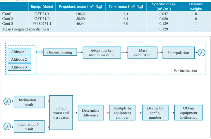
For those equipment and components whose capacity at irst is not deined by its mass, it will be necessary to convert them in equipment mass. Table 1 shows an example of the speciic capacity used to implement this conversion for the tank. hree commercial tanks could be used (based on the last column only the coniguration 3 is being used) and the speciic mass corresponds to the rate between the tank mass and the propellant mass. he last column can be used to assign a relative weight to each coniguration.
he platform ineiciency will be determined by the platform mass difference. The mass of all covered equipment and required for each mission attribute (comprehensiveness) will be determined. he highest and lowest platform masses will be considered as the worst and best cases respectively. Bogossian and Loureiro (2012) presented a preliminary version of the method. To determine the platform eiciency for a given comprehensiveness, the method uses four different models according to platform equipment. Only the basic model is presented here (Fig. 1). his model applies to the tank, reaction wheels, torque rods and battery.
he dimensioning is signiicantly dependent on the highest and lowest altitudes, reason why the method interpolates the altitude range of the platform being assessed with respect to the three altitudes considered by the method. Considering all inclinations, the inefficiency is the difference between the worst and the best cases multiplied by the number of onboard equipment (by one if no redundancy) and divided by the number of diferent conigurations (scalability concept). he more over dimensioned with respect to the minimum value, the less eicient is the platform. he scalability has a signiicant efect on the platform eiciency for a given comprehensiveness. As the required component capacity varies according to the mission parameters, the utilization of diferent hardware conigurations will enable to reduce the ineiciency by choosing the appropriate coniguration for each mission.
he method has a speciic treatment for some platform equipment. For the solar wings it is always possible to use a symmetric coniguration with two identical wings or a free coniguration with one or two wings. he panels, as the main wing component, have a standard size (informed as input) and a maximum number of them in the wings.
If the equipment is dimensioned exclusively by one of the environment factors considered by the method (without being based on a budget with several factors) and if it is an of-the-shelf equipment, it is possible to adopt a minimum value to exclude from the ineiciency determination capacity values not available in the market.
he ineiciency related to the TID absorved by the electronic components of the developed equipment and absorbed by the purchased equipment does not afect directly the mass, but the cost instead. he components with higher TID capacity are more expensive. he method requires the platform designer to establish a level of TID for the components and equipment that is between the best and the worst cases, according to what is available in the market. Based on this level, the method determines the amount of additional shielding (with respect to existing boxes and platform structure) necessary to keep the TID under the maximum supported level for the lifetime. he method captures the ineiciency from the structure considering the dimensioning for several launchers. It considers only two environmental factors, the quasi-static acceleration
Table 1. Speciic mass table.
Equip. model propelant mass (m1) (kg) Tank mass (m2) (kg) Speciic mass (m2/m1)
Relative weight
Conf 1 OST 31/1 136,22 6,4 0,047 0
Conf 2 OST 31/0 80,50 6,4 0,080 0
Conf 3 PSI 80274-1 46,44 6,0 0,129 1
Mean (weighed) speciic mass 0,129 1
Altitude 1 Dimensionning Adopt market minimum value
Mass
calculation Interpolation A
Per inclination
A Inclination 1 result
Inclination N result
Obtain worst and best cases
Determine difference
Multiply by equipment number
Devide by config. number
Obtain equipment inefficency
A
Altitude 2
Altitude 3
and the decoupling of the irst platform mode longitudinal frequency from the launcher corresponding one. Each launcher has speciic values for these two factors and the platform has to consider the worst and the best cases. For the quasi-static efect the method determines the face sheet width of the top, bottom and lateral panels. he width diference between the best and the worst cases determine the amount of additional mass between both cases and corresponds to the ineiciency due to this factor. With respect to the decoupling, the method determines the bottom panel rigidity deining the panel width for the best and the worst cases. From the diference between them it is possible to obtain the ineiciency due to this factor. The mass resulting from the sum of these two effects corresponds to the structure ineiciency due to the lexibility of the platform to be launched by a set of launchers.
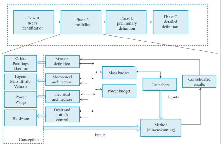
ThE mEThOD in ThE plATfORm lifECYClE The method aims to help the platform designer at the conception phase. In space project lifecycle (ECSS, 2009) it will be used at Phase A, as shown in Fig. 2. In this phase, the
platform is conceived, the launchers are deined and the mission comprehensiveness established. With these inputs the method assesses the platform and provides consolidated results (level of ineiciency) that could be used by the platform designer to modify the preliminary results.
All required data are available at Phase A such as dimensions, number of wings and wheels, required power and layout.
implEmEnTATiOn
he logic and calculation necessary for the method were implemented by using a set of spreadsheets. Twelve spreadsheets were required, one for each considered environment factor (seven at total), one for the results, two for constants, one for speciic capacities and one for the inputs.
For each case, the method shall determine the dimensioning of the equipment to cope with the corresponding environmental factor, based on well-known equations or simulation results.
he method covers satellite orbital altitudes from 400 up to 1,500 km. he highest and lowest altitudes are essential to determine the worst and the best cases. If the altitude range
Phase 0
needs identification
Orbits Pointings
Lifetime
Mission definition
Mass budget
Launchers
Inputs
Inputs
Method (dimensionning)
Consolidated results
Power budget Mechanical
architecture
Electrical architecture
Orbit and attitude control Layout
Mass distrib. Volume
Power Wings
Hardware
Conception
Phase A feasibility
Phase B preliminary
definition
Phase C detailed definition
implemented by the method is higher than the platform altitude range under evaluation, the method will interpolate the corresponding values with the best curve.
he next items describes, for each environment factor, the implementation characteristics.
Drag
he atmospheric drag is one of the environmental factors (the others are not considered by the method) that will afect the amount of propellant necessary to maintain the nominal orbit. Based on the drag force, the method determines the amount of propellant needed for each case during a year timeframe, considering the mean orbit attack angle, the air density based on Jacchia model (Jacchia, 1977), the satellite external surface, the orbital speed, the drag coeicient and the accepted orbit error. he minimum mean attack angle was determined by computing simulation (STK, version 8.12).
Aerodynamic Torque
he aerodynamic torque is one of the environmental factors that affect the reaction wheels dimensioning. The angular momentum capacity is dimensioned by the method for each case. he drag force is also used for torque determination, based on the position of the center of pressure with respect to the center of mass.
he reaction wheel mass is strongly dependent on the capacity to store the angular momentum, for a given maximum rotation speed. The angular momentum determination is based on the center of pressure (wings and body), center of mass, number of wings and number of orbits to store the momentum. he required wheel capacity is determined by the torque integration in a speciied number of orbits, per axis. All wheels are dimensioned with the same capacity, being considered the highest axis value.
Magnetic Field
he Earth magnetic ield deines the torque rods dimensioning necessary to unload the reaction wheels. By simulation (STK, version 8.12) is obtained, for each case and axis, the minimum annual value of the mean orbit magnetic ield. he rods must produce a torque that generates a negative angular momentum with respect to the stored momentum. he unload process considers the same number of orbits accounted in the wheels dimensioning. All rods will be dimensioned with the highest axis value.
Sun
For each case considered, the method determines the solar panel surface area necessary to provide the minimum power established by the platform, always using the same surface area per panel. he method considers conigurations with always two wings or one or two wings. A ixed mass is considered per wing (e.g. yoke, hold-down, SADA). By simulation (STK, version 8.12) it is obtained the worst orbit case in a year period. All necessary eiciencies were considered in the implementation.
Eclipse
For each case, the annual maximum eclipse duration is determined by simulation (STK, version 8.12), dimensioning the battery capacity. Some inputs required by the method are eiciencies, minimum bus voltage, required power and mean Depth of Discharge (DoD).
Total Ionizing Dose
Based on simulations (SPENVIS, 2011), the method included several TID tables. Based on these tables the method determines the equipment/components absorbed TID, considering only the basic shielding (platform structure and equipment boxes for the components). When the dose exceeds the component/equipment speciication, the shielding is increased by including aluminum plates in parallel with the electronic boards, ensuring that the absorbed dose will remain within the speciication. he method requires inputs such as lifetime, component/equipment TIDs and quantity and size of the boxes.
Launchers
The implementation for the quasi-static acceleration is based on analytical solution for sandwich plates, supported by a rigid frame. The top panel is in simple square supported (by the frame) coniguration with an uniform distributed load on the panel. his implementation is based on the launcher’s maximum acceleration and the platform layout that informs in which panel each equipment is located. he relation between the dimensioning between two launchers (best and worst cases) produces the face sheet width diference. From the panel geometry and the adopted material, it is obtained the additional mass between the worst and the best cases. For the lateral panels, the same process is applied taking into account the lateral acceleration.
an uniformely distributed load. he mass directly placed over the interface is ignored.
For the irst mode minimum frequency (decoupling factor), an analytical solution is also considered. he launcher-satellite interface is a rigid supported circle. he dimensioning result is the bottom panel width necessary to place the irst longitudinal frequency above a speciied value, for a given launcher. Taking into account the worst and the best cases, it is possible to obtain the mass diference between both cases, considering also the informed geometry and adopted material.
mEThOD OUTCOmES
he method outcome is the ineiciency mass of each onboard equipment, the total direct and indirect masses and the ineiciency percentage with respect to the platform and the satellite (see example in Application Case section). hese percentages could be used as a subjective absolute value or relative value to assess the actions eicacy. A recommended approach is the variation of several orbits and platform parameters to determine the efect of each one (sensitivity analysis). he parameters that slightly reduce the comprehensiveness and increase signiicantly the eiciency are the most suitable to be adopted.
Bogossian et al. (2011) presented a preliminary version of this method without considering scalability and structure.
APPLICATION CASE
he PMM project began in 2001 at INPE with the objective of providing the necessary means of producing low Earth orbit satellites in a reduced time and cost. he irst satellite is the Amazonia-1, shown in Fig. 3, a remote sensing satellite planned to be launched in 2014. he satellite dimensions are 2.35 x 0.95 x 0.95 m. he total mass is 550 kg and the platform mass is around 300 kg. he satellite is pointed to nadir and it has always two wings with a total surface of 6.3 m2 with a SADA (Solar Array Drive Assembly) to rotate the wings.
Considering that the PMM (INPE, 2001) platform is already designed and it is too late to be balanced by the method, the application case was included in this paper only to exemplify the method outputs. A sub set of tables is shown in this work to give a real meaning of the method outcomes. Table 2 shows the result of the tank dimensioning process for the considered cases including diferent orbits (three altitudes and some inclinations), pointing targets and quantity of solar wings. he method determines the mass value
that corresponds to the fraction of the tank necessary to store the amount of propellant required to keep the orbit within the established error limit for the lifetime. Table 2 shows data only for the applicable cases (two-wing coniguration, W = 2). It is remarked in yellow, the interpolation for the PMM orbit range. Considering that the PMM range of altitudes (600–1,200 km) is lower than the method range altitudes (400–1,500 km). Figure 4 shows the interpolation curve to estimate the required tank mass for the PMM altitude range. In the last two lines, Table 2 informs that PMM has on board only one tank, and it informs also that was considered by the project, only one tank size (# Conig.).
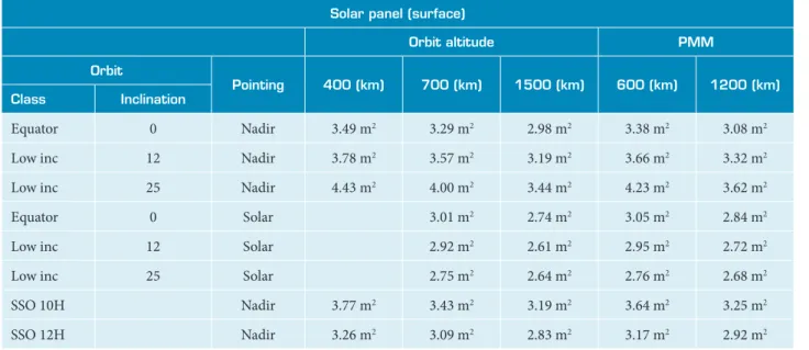
Table 3 shows the required panel surface area for each case and Table 4 presents the total number of solar panels (considering a 1m2 panel) and wings mass.
Table 5 shows the consolidated results. he irst seven rows show the equipment mass diference between the worst and the best cases, representing the ineiciency of each one (obtained from Tables 1 to 4). Row 8 represents the total direct mass (excluding only the shielding mass) and line 9 includes all equipment. Rows 10 and 11 present the platform and satellite (Amazonia-1) masses
Figure 3. Amazonia -1 satellite.
Figure 4. Interpolation curve.
Tank Mass Kg
Km
27
0.70 0.00
0 500 1000 1020
30.0
25.0
20.0
15.0
10.0
5.0
0.0
Table 2. Tank dimensioning.
Tank mass
Orbit
pointing # Wings
Orbit altitude pmm
Class inclination 400 (km) 700 (km) 1500 (km) 600 (km) 1200 (km)
Equator 0 Nadir 1 NA NA NA NA NA
2 27.25 km 0.70 0.00 3.47 km 0.09 km
Low inc 12 Nadir 1 NA NA NA NA NA
2 27.25 km 0.70 0.00 3.47 km 0.09 km
Low inc 25 Nadir 1 NA NA NA NA NA
2 27.25 km 0.70 km 0.00 km 3.47 km 0.09 km
Equator 0 Solar 1 NA NA NA NA
2 0.88 km 0.01 km 1.39 km 0.04 km
Low inc 12 Solar 1 NA NA NA NA
2 0.88 km 0.01 1.37 km 0.04 km
Low inc 25 Solar 1 NA NA NA NA
2 0.86 km 0.01 km 1.36 km 0.04 km
SSO 10H 97/98 Nadir 1 NA NA NA NA NA
100 2 27.25 km 0.70 km 0.00 km 3.47 km 0.09 km
SSO 12H 97/98 Nadir 1 NA NA NA NA NA
100 2 27.25 km 0.70 km 0.00 km 3.47 km 0.09 km
max: 3.47 min: 0.04 Unit: 3.43 inef: 3.43
# Conig: 1 # tanks: 1
Table 3. Required surface for solar panels.
Solar panel (surface)
Orbit altitude pmm
Orbit
pointing 400 (km) 700 (km) 1500 (km) 600 (km) 1200 (km) Class inclination
Equator 0 Nadir 3.49 m2 3.29 m2 2.98 m2 3.38 m2 3.08 m2
Low inc 12 Nadir 3.78 m2 3.57 m2 3.19 m2 3.66 m2 3.32 m2
Low inc 25 Nadir 4.43 m2 4.00 m2 3.44 m2 4.23 m2 3.62 m2
Equator 0 Solar 3.01 m2 2.74 m2 3.05 m2 2.84 m2
Low inc 12 Solar 2.92 m2 2.61 m2 2.95 m2 2.72 m2
Low inc 25 Solar 2.75 m2 2.64 m2 2.76 m2 2.68 m2
SSO 10H Nadir 3.77 m2 3.43 m2 3.19 m2 3.64 m2 3.25 m2
used as reference. Rows 12 to 15 present the relative ineiciencies in terms of percentage with respect to the platform and satellite masses. Rows 16 to 18 show the best cases for all in the same orbit, corresponding to the orbit with the lowest total equipment mass. In order to demonstrate how the method is used for balancing the comprehensiveness in terms of altitude with the eiciency, the lowest altitude was reduced from 600 to 550 km as a irst case and increased from 600 to 650 km as second case. he result for the irst case was an increase in the total ineiciency mass from 29.4 to 31.9 kg (increase of 2.5 kg) that corresponds to an ineiciency increasing from 10.0 to 10.8%. For the second case, the total mass decreased to 27.5 kg (decrease of 1.9 kg) and that corresponds to an ineiciency reduction from 10,0 to 9.3%.
CONCLUSIONS AND FURTHER WORK
he main result of this work is the demonstration that it is possible to obtain an objective platform penalty measurement. It enables, for the products developed by using the sequential approach, to have a feedback from the adopted comprehensiveness with respect to the eiciency. he method itself represents a tool to help space platform designer to balance eiciency with comprehensiveness.
he method scope was reduced for this irst version based on the real cases, and it requires further work to augment its scope in terms of space and launching environments as well as platform coniguration. It is also recommended that some of the implemented models be upgraded to improve the process of capturing the ineiciencies.
Table 4. Required panels and wings mass.
Always two wings
# panels (*) fx mass Total kg
Orbit
pointing 600 1200 (kg) 600 (km) 1200 (km)
Class inclination (#) (#)
Equator 0 Nadir 4 4 9.596 24.69 24.69
Low inc 12 Nadir 4 4 9.596 24.69 24.69
Low inc 25 Nadir 6 4 9.596 32.24 24.69
Equator 0 Solar 4 4 2.856 17.95 17.95
Low inc 12 Solar 4 4 2.856 17.95 17.95
Low inc 25 Solar 4 4 2.856 17.95 17.95
SSO 10H Nadir 4 4 9.596 24.69 24.69
SSO 12H Nadir 4 4 9.596 24.69 24.69
Max: 32.24 Min: 17.95 Min. Without Sada 24.69
Inef: 7.55
(*) Always even
Table 5. Consolidated results.
Total pmm
Component mass (kg)
1 Tank 3.43
2 Wheels 0.74
3 Magnetic torque rods 1.88
4 Solar wings 7.55
5 Battery 1.81
6 Structure 7.29
7 Shielding (indirect mass) 6.67
8 Ineiciency direct mass 22.7
9 Ineiciency total mass 29.4
10 Platform mass 295
11 Satellite mass 557.0
12 % Inef. Direct platform 7.7%
13 % Inef. Direct satellite 4.1%
14 % Inef. Total platform 10.0%
15 % Inef. Total satellite 5.3%
16 Total inef. Mass lowest orbit 28.68
17 % Tot. Inef. Lowest orbit - platform 9.7%
REFERENCES
Aerospatiale and Sextant, 1995, “Aerospatiale/Sextant Avionique
brochure”,Filière Proteus CNES.
Alary, D. and Lambert, H., 2007, “The Myriade product line, a real success story”, ACTA Astronautica, Vol. 61, pp. 223-227.
Boas, R.C. and Crawley, E.F., 2006, “Extending Platforming to the Sequential Development of System Families”, INCOSE 2006, 16th Annual International Symposium Proceedings. Orlando, Florida.
Boas, R.C. and Crawley, E., 2007, “Parallel and Sequential Development of Complex Platform-Based Product Family”, Engineering Management Conference, IEEE.
Bogossian, O.L. and Loureiro, G., 2011, “Attributes Balance on the Adoption of Platform Based Solutions for Satellites”, Concurrent Engineering Proceedings, MIT, Cambridge, MA, USA.
Bogossian, O.L. and Loureiro, G., 2012, “Attributes Balance on the Adoption of Platform Based Solutions for Satellites”, Journal of Aerospace Engineering, Sciences and Applications, Vol. 4, No.1. pp. 110 - 115.
Bogossian, O.L., Loureiro, G. and Lopes, R.V.F., 2011, “Architecting Method to Assess Conceptual Design of Platform Based Satellites”, International Astronautical Congress, Cape Town, South Africa. IAC-11.D1.6.3.
Bouzat, C., 2000, “CNES Microsatellite Product Line, an approach for innovation”, Small Satellites Systems and Services, 5th International Symposium, La Boule France.
Buisson, F., Cussac, T., Lassalle-Balier, G., Laurens, A., Ledu, M., Llorens, J.C. and Chadoutaud, P., 1998, “La ligne de produits Micro-satellite du CNES”, Small Satellites Systems and Services, 4th International Symposium, Antibes, San Juan Les Pains, France.
Cussac, T., Buisson, F. and Parrot, M., 2004, “The Demeter Program:
Mission and Satellite Description – Early in Flight Results”, 55th
International Astronautical Congress, 2004 IAC-04-IAA.4.11.2.04. Vancouver, Canada.
Dechezelles, J.J. and Huttin, G., 2000, “PROTEUS: A Multimission Platform for Low Earth Orbits”, Air & Space Europe, Vol. 2, No. 1, pp. 77-81.
European Cooperation for Space Standardization (ECSS), 2009, “System Engineering General Requirements”, ECSS. [S.1].
Galeazzi, C., 2000, “Prima: A new, competitive small satellite platform”, Acta Astronautica, Vol. 46, No. 2-6, pp. 379-388.
Gonzalez-Zugasti, J.P. and Otto K.N., 2000, “Platform-Based Spacecraft Design: A formulation and implementation Procedure”, Aerospace Conference Proceeding, IEEE.
Gonzalez-Zugasti, J.p., Otto K.N. and Baker J.D., 2000, “A Method for Architecting Product Platforms”, Research in Engineering Design, Vol. 12, No. 2, pp. 61-72.
Grivel, C., Doullet, F., Huiban, T., Sainct, H., Bailion, Y., Terrenoire, P. Schrive, J. and Lazard, B., 2000, “Proteus: European Standard for small satellites”, Small Satellites Systems and Services, 5th International Symposium, La Boule France.
National Institute for Space Research (INPE), 2001, “Multimission Platform: Data Package for System Requirement Review”, INPE’s Internal Document.
Jacchia, L.G., 1977, “Thermospheric Temperature, Density and Composition: New Model”, Research in Space Science SAO Special Report No. 375, Smithsonian Institution.
Pine, B.J., 1993, “Mass customization: The new frontier in business competition”, Harvard Business School Press, Boston.
Meyer, M. and Lehnerd, A.P., 1997, “The power of product platform – building value and cost leadership”, Free Press, New York.
Meyer, M. and Utterback, J., 1993, “The product family and the dynamics of core capability”, Sloan Management Review, Vol. 34, No. 3, pp. 29-47.
Muffatto, M., 1999, “Introducing a platform strategy in product development”, International Journal of Production Economics, Vol. 60-61, pp. 145-153. doi: 10.1016/S0925-5273(98)00173-X
Software Satellite Took Kit (STK Analytical Graphics, Inc.) version 8.12 Expert Edition.