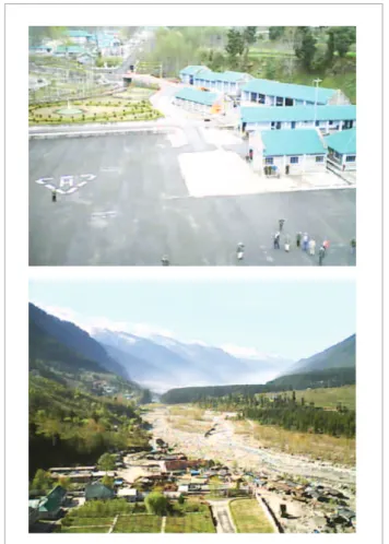
ABSTRACT: A remotely controlled airship was designed, fabricated and demonstrated within a tight timespan of under a month after receiving the go-ahead. The main design requirement for this airship was to be able to operate from a Helipad located at an altitude of 6,572 feet AMSL under ISA+20 deg.C. The images of the terrain below were recorded during the light and transmitted in real-time to a ground based system using an onboard telemetry system. The paper describes the methodology followed for sizing of the envelope and key components of the airship, and the procedure followed for in-house fabrication and testing. The major issues that cropped up during the operation of the airship in harsh weather conditions of rain and mild snow, as well as at night, are also highlighted. The demonstration established the eficacy of remotely controlled airships for aerial photography and data collection by snow scientists.
KEYWORDS: Lighter-Than-Air systems, Airships, Blimps.
Design, Fabrication and Flight
Demonstration of a Remotely Controlled
Airship for Snow Scientists
Rajkumar Sureshchandra Pant1
INTRODUCTION
Aerial surveillance usually requires monitoring the activities of people and/events over a designated area and long period of time from an airborne platform. A monitoring process such as this would essentially be based on steady visuals from the area of interest. he design features and attributes that an aerial surveillance airborne platform must possess should help accomplish this mission completely and eiciently. For instance, such a system should have the ability to take-of and land vertically or from limited areas, since such airborne platforms may need to operate from remote locations, some of which might lack large lat open areas to get airborne and/or land.
he onboard surveillance equipment suite has to steadily focus on the desired area on the ground, from a particular altitude. he quality of the surveillance is directly related to the level of stability that the platform can ofer. Hence the airborne platform must be able to hover at an altitude and stay put without causing serious luctuations to the dynamic surveillance data collection. he platform should be considerably inert to disturbances like crosswind, gust, wavering of the payload surveillance equipment due to maneuvering and induced vibrations by the platform itself.
he platform should also require minimal expertise for operation, and the cyclic procedure from storage to deployment should be prompt and easy. Another important attribute is low cost of manufacture and operation of the system, not to mention the strict environmental regulations that need to be adhered to in this age of rapid degradation of our planet. Hence an airship is arguably the most suitable and preferred prospect
1.Indian Institute of Technology Bombay – Mumbai/Maharashtra – India
Author for correspondence: Rajkumar Sureschandra Pant | Adi Shankaracharya Marg, Powai | 400076 Mumbai/Maharashtra – India | Email: [email protected]
for an aerial surveillance system, taking into account all the above mentioned desirable attributes of such a system.
Airships are aerodynamically shaped bodies illed with a “Lighter-han-Air” (LTA) gas that displaces the ambient air, which results in a net upward force due to buoyancy. his is called static (or buoyant) lit, since it is due to the inherent buoyant force, which is generated even when airship is stationary. In addition, an airship also can generate dynamic lit due to the action of aerodynamic forces acting on it as it moves through the air, just like an airplane. Once airborne, airships can perform much like helicopters, remaining nearly geo-stationary for extended periods of time, albeit with much lesser fuel consumption, and noise and vibration levels. A remotely controlled (RC) airship is perhaps much more suitable than a remotely controlled aircrat for aerial surveillance due its long endurance loiter and lower fuel consumption.
Design, fabrication and light testing of prototypes of several LTA systems for various scientiic applications has been carried out at IIT Bombay since 2002 (Gawale and Pant, 2002). Some recent projects include indoor remotely controlled airships for neural network control hardware implementation (Sangole et al., 2006), aerostats as platforms for low-cost re-locatable wireless communications systems (Gawande et al., 2007), outdoor remotely controlled airships for product promotion (Gawale et al., 2008), aerial river ferry using superheated steam-illed balloons (Banerjee et al., 2008), and aerostats for snow cover evaluation (Bhandari and Raina, 2009). he following sections highlight the design process and fabrication.
DESIGN PROCESS
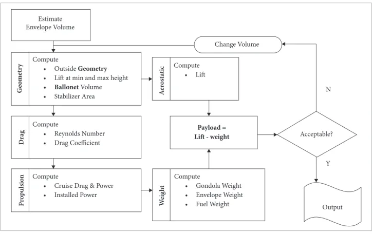
An RC airship can broadly be divided into the ive main components, viz., Envelope, Stabilizer and Fins (empennage), Gondola, Propulsion system and Remote Control system. he conceptual design and sizing of the airship is based on the methodology developed by Pant (2008), utilizing the aerostatic and aerodynamic analysis described in Cheeseman (1999). his methodology arrives at the baseline speciications of a manned airship with inputs on the user speciied performance and operational requirements and has been suitably adapted by Gawale et al. (2008) for the design and sizing of RC airships. he scheme of arriving at baseline speciications of an airship to meet the user-speciied operating and performance requirements is shown in Fig. 1.
DESIGN REQUIREMENTS
The key requirement of the RC airship was the ability to deploy the airship from a Helipad located at an altitude of 6,572 ft. AMSL, while carrying a payload camera that could take high resolution photographs of the terrain below and transmit them in-real time. As we shall observe later, the airship had to operate in very cold weather at a high altitude and the envelope material selection and fabrication process had to conform to such harsh environmental conditions. In addition, the airship specifications included limitations on its length and volume. As mentioned earlier, adequate stability of the airship during flight would obviously generate clear photographs for surveillance and this requires the airship to be controlled effectively. The stabilizers and fins were also designed keeping this requirement in mind. Of all these, the prime concern was of the propulsion system which needed to operate at altitudes where density of the air is lower than at sea level. Table 1 lists some of these key design requirements for the airship.
Table 1. Airship design requirements.
Parameters Value
Payload 3 kg
Operating altitude 200 t AGL
Base station altitude 6,572 t AMSL
Design wind speed 15 m/s
Of Standard temperature 20°C
Operational time 15 days
Apart from the above mentioned requirements, which describe a more involved design process, more oten than not we also have the constraint on lowering the cost of manufacturing and operation to a level acceptable to user.
he following sections briely explain the design of the important components of the RC airship.
ENVELOPE DESIGN
Estimate Envelope Volume
Compute
• Outside Geometry • Lit at min and max height • Ballonet Volume
• Stabilizer Area
Compute
• Reynolds Number • Drag Coefficient
Compute
• Cruise Drag & Power • Installed Power
Compute
• Gondola Weight • Envelope Weight • Fuel Weight
Compute
• Lit
Acceptable?
Output
Y
N
Payload = Lit - weight
Change Volume G eom et ry D rag Pro p u ls io n We ig h t A er os ta ti c
Figure 1. Scheme for determination of baseline specii cations of an airship.
(1)
where M is the bending moment and Pint is the internal static pressure.
h e pressure distribution on the outer envelope surface has been calculated to identify the points with maximum dif erential pressure. h e total dif erential pressure was estimated using the equation given below:
(2)
where Paero is the dynamic pressure, Pint is the internal static pressure and h is the radius of the envelope.
h e center of pressure of this section is located at 33% of its length, which is also the point at which maximum dif erential pressure occurs. h e l ow over the hull is assumed to be turbulent and the drag is estimated in terms of drag coei cient CDV, maxitmum velocity, volume and the reference area from the formula
(3) Ellipse
1 .2 5d 1 .6 2 5d
Circle
0 .1 7 5d
Parabola
y
x
3 .0 5d
Nose Ellipse - origin to 1.25d:
Middle Circle - 1.25d to 1.62d:
Tail Parabola - 1.62d to 1.8d:
d = 2623 mm
Figure 2. Geometrical Construct of GNVR proi le.
sections, and its entire geometry is analytically parameterized in terms of its max diameter d. h e length and volume of the airship GNVR envelope shape are 8 m and 26.64 m3. Experimental
(Narayana and Srilatha, 2000) and numerical (Sundaram, 2000) studies have shown that this shape is very well suited for tethered aerostats operating at an altitude up to 1 km.
The envelope material has to be appropriately chosen to ensure adequate strength, durability, as well as low weight. A qualitative comparison of the properties of various fabrics that are used for load bearing was carried out and a light weight, yellow coloured PVC fabric was used, keeping in mind the weight, cost and availability constraints. The key properties of this material are listed in Table 2 (Gupta and Malik, 2002).
PROPULSION SYSTEM
A detailed overview of the power plant system, design issues in engine sizing and selection, advances in engine technology, various concepts for thrust vectoring and a methodology for sizing and selection of design features of an airship engine has been outlined by Gawale and Pant (2004). he speciications of the engine used for this airship have been listed in Table 4.
Table 2. Properties of envelope material used for airship.
Property Value
H2 permeability @ 25 cm H2O column 3.75 liters/m2/day
Break strength along warp direction 1.68 kg/cm
Break strength along wet direction 1.76 kg/cm
Speciic weight 0.14 kg/m2
hickness 0.11 mm
STABILIZER AND RUDDER
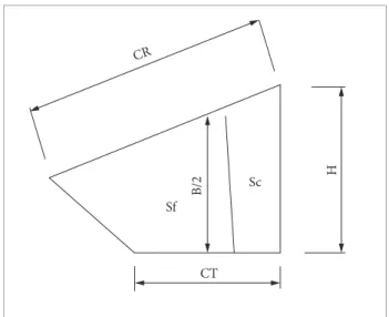
he stabilizer and rudder have been designed to have a cruciform shape on the envelope and the procedure for sizing has been adopted from Gawale and Pant (2002) by scaling down the dimensions of the stabilizer and rudder of existing airships. However, care has been taken to ensure that the scaling is done using data of airships which have envelopes of similar shapes and ineness ratios. A schematic view of the stabilizer for the airship is shown in Fig. 3 and its relevant dimensions are tabulated in Table 3.
H
CT Sf
B/2 Sc
CR
Figure 3. Schematic of the stabilizer & rudder.
Table 3. Dimensions of the stabilizers.
Parameter Fixed surface Moving surface
Surface area 0.61 m2 (S
f) 0.13 m
2 (S c)
C
T (tip chord) 0.86 m 0.17 m
C
R (root chord) 1.45 m 0.30 m
H (height) 0.86 m
B/2 (mean half span) 0.69 m
Table 4. Speciications of the engine.
Type 0.15 LA-S (OSMG1415)
Displacement 2.49 cc
Bore 15.2 mm
Stroke 13.7 mm
RPM 2,500 to 18,000
Power output 0.41 BHP @ 17,000 rpm
Mass 0.13 kg
STABILITY ANALYSIS
FABRICATION
his section briely outlines the fabrication methods of the components of the airship.
ENVELOPE
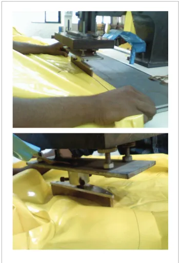
he envelope is usually constructed by joining smaller sections called petals, as seen in Fig. 4, which are cut out from the fabric sheets using a shape template. he shape template consists of the cross-sectional shape of the envelope generated using the coordinates of the GNVR proile. he envelope petals were then seamed together, as shown in Fig. 5, depending on their orientations using radio frequency (RF) heat welding, thereby forming the whole envelope.
Table 5. Component mass and center of gravity distribution.
Component Weight (kg) CG location
from nose (m)
Envelope 12.53 3.74
Fin velcro strip + hooks 0.59 6.60
Fins 1.32 6.97
Batons 0.70 0.50
Gondola 3.00 3.01
Airship assembly 18.14 3.82
Ballast 3.37 3.64
Total weight 21.51 3.79
Figure 4. Envelope proile.
2.0
1.0
0.0
-1.0
-2.0
2.0 4.0 6.0 8.0
Figure 5. Radio frequency welding of petals.
GONDOLA
he gondola was sized to accommodate the receiver, battery package, fuel tank, engine and payload. he gondola mounting slots were welded below the envelope and the gondola has been attached directly to the envelope using contoured aluminum rods going into these slots. It was carefully set up upon determining its location and mass, to have as stable an airship as possible.
STABILIZER AND RUDDER
Figure 6. Stabilizer and Rudder.
FLIGHT DEMONSTRATION
Some of the major concerns dealt before the light testing was of transportation and leak testing of the envelope. he envelope underwent a leak detection test, where light sources illuminated the holes, if any. Subsequent to the gas leak testing was the complete integration of all the sub-assemblies and the inlation of the envelope with Helium. he CAD model of the airship along with the ins and a side view of airship are shown adjacently in Fig. 7. It was observed that an additional ballast weight had to be added to the gondola in order to attain stability.
Figure 7. CAD model and airship side view.
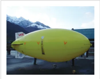
he airship was successfully lown during three diferent weather conditions, viz., dry day, mild rain and mild snowfall. he low density of air at such a high altitude could always resulted in reduced performance of a propeller engine and a small engine set up can amplify this problem. Despite this, the light performance was quite satisfactory with comfortable take of and climbing light. he airship was also maneuvered to undergo both level and climbing turning light, including a touch-down and take-of, which demonstrated its control efectiveness. he completely fabricated airship is shown in Fig. 8. Figure 9 shows some of the images of the airship during its light.
Figure 8. Airship upon complete fabrication.
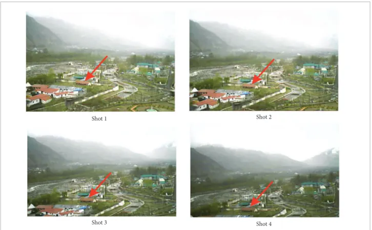
he airship carried an operating payload which consisted of an autofocus Internet Protocol (IP) camera, which took live footage during its light. he IP camera was capable of continuously taking photographs at the rate of around one photograph per second and the transmitted sequence of pictures were then combined in a video by playing them at a faster rate. Figure 10 shows the photograph of IP camera mounted on the front of the gondola.
Figure 9. Airship during light.
Figure 10. IP camera.
Figure 11. Two aerial photographs taken by onboard IP camera.
CONCLUSIONS
REFERENCES
Banerjee, S., Raina, A.A. and Pant, R.S., 2008, “Low Cost Trans-river Aerial Ferry”, Proceedings of AIAA’s 8th Aviation Technology Integration and Operations (ATIO) Conference, Anchorage, Alaska, USA, AIAA-2008-8851.
Bhandari, K.M. and Raina A.A., 2009, “Conceptual Design Of A High Altitude Aerostat For Study Of Snow Pattern”, Proceedings of International Symposium on Snow & Avalanches (ISSA-09), SASE, Manali, India.
Cheeseman, I., 1999, “Aerodynamics”, In: Khoury, G.A. and Gillet, J.D., Airship Technology, Cambridge Aerospace Series 10, Cambridge University Press, New York, pp. 25-38.
Gawale, A.C. and Pant, R.S., 2002, “Design, Fabrication and Flight Testing of Remotely Controlled Airships”, Proceedings of
National Conference on LTA Technologies, Aerial Delivery R&D Establishment, Agra, India.
Gawale, A. and Pant, R., 2004, “Design Studies of a Powerplant System of Non-Rigid Airship”, Proceedings of the 5th International Convention of the Airship Association, Oxford, England.
Gawande, V.N., Raina A.A., Bilaye, P., Pant, R.S. and Desai, U.B., 2007, “Design and Fabrication of an Aerostat for Wireless Communication in Remote Areas”, Proceedings of AIAA’s 17th Aviation, Technology, Integration, and Operations (ATIO) Conference and 17th Lighter-Than-Air Systems Technology Conference, Belfast, Northern Ireland, UK, AIAA-2007-7832.
Gawale, A., Raina, A.A., Pant, R.S. and Jahagirdar, Y.P., 2008, “Design Fabrication and Operation of Low Cost Remotely Controlled
ACKNOWLEDGMENTS
h e author would like to thank Dr. R. N. Sarwade, Director, and Mr. Jimmy Kansal, Deputy Director of Snow and Avalanches Study Establishment, DRDO, for inviting the team from LTA systems Lab. of IIT Bombay to carry out the demonstration l ight of this airship, and express his gratitude
Figure 12. Sequence of photographs taken by the onboard camera.
Shot 1 Shot 2
Sh ot 3 Sh ot 4
Airships in India”, Proceedings of AIAA’s 18th Aviation Technology Integration and Operations (ATIO) Conference, Anchorage, Alaska, USA, AIAA-2008-8853.
Gupta, S. and Malik, S., 2002, “Envelope Details for Demo Airship”, PADD Project Report, Aerial Delivery R&D Establishment.
Narayana C.L. and Srilatha, K.R., 2000, “Analysis of aerostat conigurations by panel methods”, BLISS Project Document CF 0010, National Aerospace Laboratories, Bangalore, India.
Pant, R.S., 2008, “Methodology for Determination of Baseline
Speciications of a Non-rigid Airship”, Technical Note, AIAA Journal of Aircraft, Vol. 45, No. 6, pp. 2177-2182.
Sangole, R., Agashe, S., Palshikar, K. and Nakanekar, G., 2006, “Design, Fabrication and Testing of Remotely Controlled Indoor Airship employed for Neural Networks Hardware Experimentation”, Undergraduate Project Thesis, Mechanical Engineering Department, PVG College of Engineering, University of Pune, India.