Mario Martins
[email protected] Federal University of Santa Maria Mechanical Engineering Department Avenida Roraima, 1000 97105-900 Santa Maria, RS, BrazilHua Zhao
[email protected] School of Engineering and Design Brunel University Uxbridge UB8 3PH United KingdomPerformance and Emissions of a
4-Cylinder Gasoline Engine with
Controlled Auto-Ignition
Advanced combustion modes such as Controlled Auto-Ignition or Homogeneous Charge Compression Ignition have been under much attention due to their ability to reduce both emissions and fuel consumption. Thus, this paper aims at demonstrating the achievement of Controlled Auto-Ignition combustion on a standard 4-cylinder gasoline engine with negative valve overlap (NVO) and analyzing its performance and emissions. The engine remained with substantially original components. The only major modification was the replacement of the camshafts for a new set of bespoke ones. The results showed a fair range of load and speed under CAI combustion with reduced brake specific consumption and ultra-low levels of NOx emissions. CO was also reduced, while HC emissions showed increased values. The results also point out some of the drawbacks of CAI combustion and the technological challenges of this advanced combustion process.
Keywords: CAI, HCCI, emissions, NVO
Introduction1
The past few years have shown a rising interest in alternative combustion modes such as CAI/HCCI, which are seen as promising technologies to reduce both fuel consumption and emissions from internal combustion engines. The last decade has brought intense investigation and remarkable improvements in knowledge of such technologies. CAI/HCCI shows a great potential in lowering both fuel consumption and emissions levels, in a substantially standard engine concept. Moreover, it may avoid the need for expensive and complicated exhaust after-treatment systems (Stanglmaier and Roberts, 1999).
CAI combustion is a process that combines SI and CI engine characteristics. It relies on the compression and charge heating to promote auto-ignition of a premixed and often homogeneous combustible charge. This combustion process enables the auto-ignition of very lean or diluted mixtures, by controlling temperature and composition of the charge, thus lowering combustion temperature and substantially reducing NOx emissions. It allows WOT operation and virtually eliminates throttling losses, resulting in significant improvement in the part-load fuel economy of an otherwise normal gasoline spark-ignited engine.
CAI combustion was first studied in the late 1970s by Onishi et al. (1979) (the ATAC paper) and Nogushi et al. (1979) working with conventional 2-stroke gasoline engines. The first results with a 4-stroke gasoline engine were achieved with intake charge heating, as reported by Najt and Foster (1983). The effects of varying A/F ratio, EGR levels, fuel type, and compression ratio on emissions and the attainable HCCI range were studied by Thring (1989).
Christensen, Hultqvist, and Johansson (1999) experimented with various fuels, different compression ratios and intake charge temperatures. Lavy et al. (2000) presented results about the first 4-stroke engine that was able to achieve CAI over a limited load and speed range by means of exhaust gas trapping using bespoke camshafts for negative valve overlapping.
Law et al. (2000) and Milovanovic et al. (2005) demonstrated the use of a fully variable valve train (FVVT) in a single cylinder research engine for CAI combustion. The influence of valve timing for controlling CAI combustion was studied.
The most common strategies for achieving CAI combustion can be summarized as:
1. Intake charge heating;
2. Higher compression ratio;
Paper received 11 January 2012. Paper accepted 17 July 2012 Technical Editor: Luís Fernando Silva
3. More auto-ignitable fuel; 4. Recycling of burnt gases.
Exhaust gas recycling appears to be the most practical for obtaining CAI combustion in a gasoline engine, especially if it is done by means of trapping exhaust residuals using the negative valve overlap (NVO) approach as reported by Law et al. (2000b), Milovanovic et al. (2005b), Zhao (2007), and Li, Zhao and Ladommatos (2001).
Possibly the major disadvantage of CAI combustion is its limited range of operation. Methods of increasing this envelope are very necessary. At the boundaries of the CAI range, cycle-by-cycle variations can increase considerably, eventually leading the engine to misfire and stall. In such a situation, it has been shown that spark assistance could help trigger CAI combustion (Wang et al., 2006). Also, in order to improve CAI range, forced induction has been employed. Research has been done to investigate the effects of forced induction on a gasoline engine with residual gas trapping. Boost was supplied from an external air compressor. A substantial increase in the upper limit of load range could be achieved without auxiliary intake heating, while NOx emissions were typically low (Yap, Megaritis and Wyszynski, 2005a,b). Several other methods of forced induction have been studied and demonstrated similar results (Christensen and Johansson, 2000; Olsson and Johansson, 2004; and Olsson et al., 2001, 2003).
This experimental research, therefore, demonstrates the operation of a standard 4-cylinder gasoline engine with port fuel injection (PFI) under CAI combustion. The results are presented and analyzed in comparison to those of the original spark-ignited operation. Engine performance and emissions were assessed and results were discussed.
Nomenclature
BMEP = brake mean effective pressure, bar
BSCO = brake specific carbon monoxide emissions, g/kWh BSFC = brake specific fuel consumption, g/kWh
BSHC = brake specific unburned hydrocarbon emissions, g/kWh BSNOx = brake specific nitrous oxide emissions, g/kWh °CA = degrees crank angle, °
CAI = controlled auto-ignition CI = compression ignition CO = carbon monoxide EVC = exhaust valve closing EVO = exhaust valve openning
HCCI = homogeneous charge compression ignition IVC = intake valve closing
IVO = intake valve openning NOx = nitrous oxide emissions NVO = negative valve overlap
PMEP = pumping mean effective pressure, bar RON = research octane number
rpm = revolutions per minute, engine speed, rpm SI = spark ignition
TDC = top dead center VCT = variable cam timing WOT = wide-open throttle Greek Symbols
λ = excess air ratio, dimensionless Subscripts
x = relative to nitrous oxides
Experimental Procedure
ENGINE SET-UP: A 4-cylinder 1.6 litre automotive engine was employed. The engine has twin independent variable cam timing sprockets (VCT). The maximum shifting range for the VCT units was 47°CA for the exhaust and 52°CA A for the intake cam. An aftermarket engine management system was used to enable real time control to all variables needed for operating the engine. The only substantial changes on the engine were the replacement of the original camshafts by a new set of bespoke low lift/small duration camshafts.
The fuel used was standard unleaded gasoline of 95 RON available in the UK. The engine was coupled to a 230 KW AC dynamometer. Exhaust measurements were carried out using a Horiba 7100-DEGR exhaust gas analyser. Emissions of Carbon Monoxide (CO), Carbon Dioxide (CO2), Oxygen (O2), Unburned Hydrocarbons (uHC) and Oxides of Nitrogen (NOx) were measured. Heat release analysis was based on in-cylinder pressure measurements using a Kistler 6121 piezoelectric transducer. Exhaust temperatures were acquired via standard K type thermocouples placed in the exhaust ports. All other temperature measurements were also done using standard thermocouples. It should be noted that all the values for pressure in this paper are given as gauge. Table 1 summarizes the engine specifications and test conditions.
Table 1. Original engine specifications.
Engine Type Inline 4-cylinder
Bore (mm) 79
Stroke (mm) 81.4
Displacement (cm3) 1596
Fuel Supply Port Injection
Compression Ratio 11:1
Fuel Gasoline 95 RON
THE CAI OPERATION: To retain the necessary exhaust residuals to allow CAI operation, the negative valve overlap strategy was used, which can be achieved by early exhaust closure and late inlet opening. However, in the case of conventional valve train with normal camshafts, simply changing the timing would not be sufficient. The change in EVC would also affect EVO. Early EVC
would result in advanced EVO, impairing the expansion stroke. This means that for running with CAI, a camshaft with smaller duration is needed. This, in turn, will result in the same cam having a smaller lift in order to keep an optimum cam profile. The same applies for the intake cam, in which only changing the timing would not be enough. Based on previous researches, a new set of cams with low lift and short durations was designed and custom built. This is shown in Fig. 1.
IVO was chosen to open always on a symmetrical position, compared to EVC, in relation to TDC, in order to minimize the back flow and energy losses. The recompression stroke after EVC and the subsequent expansion between TDC and IVO has some heat loss, creating the small pumping loop presented in Fig. 2.
Intake and exhaust valve timings are selected to be similar to previous experiments, with EVC ranging from 57°CA to 104°CA BTDC and IVO ranging from 72°CA to 124°CA ATDC.
Figure 1. Intake and Exhaust cam profiles for the short duration (bespoke) camshafts.
Figure 2. Experimental P-V diagram at 1500 rpm. P-V diagram - 1500 rpm
0 10 20 30 40 50 60 70
0 50 100 150 200 250 300 350 400 450
Volum e(cm 3)
P
re
s
s
u
re
(
b
a
r)
During the experiments the engine was kept at WOT and the air flow was varied by changing the valve timing. The engine was started in SI mode and 50% throttle and left to warm up. When the coolant temperature reached 60oC the valve timing could be changed and the throttle fully opened to allow for CAI operation, which would become more stable as the temperature continued to rise. The engine was kept, therefore, around 90oC coolant temperature to ensure maximum stability for the whole operational range. When running on CAI the spark could be turned off. However, it was left always on to avoid premature misfiring when the engine was running at highly diluted conditions, therefore increasing, slightly, the CAI range.
Results and Discussions
The engine was fuelled with standard unleaded gasoline of 95 RON. The results presented in this section were taken mostly at λ = 1.00. Load was varied mainly through valve timing
change. For example, increasing NVO with advanced EVC traps more exhaust residuals and hence reduces the volume of fresh air/fuel mixture inducted in the following cycle. At the bottom end only, load was also varied by leaning out the mixture, which showed to enable a further reduction in load. When the minimum load for stable operation at λ = 1.00 was achieved, λ was then
progressively increased up to the lean limit. For the speeds of 3000 and 3500 rpm, stable operation could only be achieved with mixtures leaner than λ = 1.05 and λ = 1.10, respectively.
Load was varied and lambda progressively increased until misfire took place. Figure 3 shows the CAI operational range.
The higher load range was limited by knock at speeds up to 2000 rpm. For higher speeds, knock was not observed and load limitation was caused only by the gas exchange reduction imposed by the short duration/low lift camshafts. For the same reason, for speeds higher than 3500 rpm the engine could not achieve stable operation anymore, when friction was also a limiting factor.
At every speed, there was a lower load limit (lowest BMEP). In this situation, a high amount of exhaust residuals was trapped in the cylinder and the exhaust temperature was already very low as shown in Fig. 4. Further increased residuals caused engine misfire, i.e. the mixture failed to auto-ignite. Even though the spark was always on, in this situation, the mixture could not ignite. Since the trapped gases are the main source of heat for auto-ignition, if the exhaust temperature at this point could be higher, a lower load limit could be achieved.
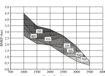
As Fig. 5 shows, fuel consumption tends to be more sensitive to load than speed, with BSFC reducing as load increases, for a fixed speed.
Figure 3. CAI combustion operational range.
B
M
E
P
(
b
a
r)
0.0 0.5 1.0 1.5 2.0 2.5 3.0 3.5 4.0 4.5 5.0
Engine speed (rpm)
500 1000 1500 2000 2500 3000 3500 4000 425
400 400
375 350
350
325
Figure 4. CAI exhaust temperature (oC).
B
M
E
P
(
b
a
r)
0.0 0.5 1.0 1.5 2.0 2.5 3.0 3.5 4.0 4.5 5.0
Engine Speed (rpm)
500 1000 1500 2000 2500 3000 3500 4000 285
300 310
335
385 410
500
Figure 5. Brake specific fuel consumption for the CAI range (g/kWh).
Figures 6 to 8 present NOx, CO and HC emissions of the CAI combustion range. Emissions of NOx are extremely low if compared to spark-ignited combustion as to be shown later. As speed goes up and load goes down, NOx emissions are further reduced. Conversely, for a fixed speed, NOx emissions increase with load due to the lower amount of residuals at this condition and to the higher combustion temperatures.
B
M
E
P
(
b
ar
)
0.0 0.5 1.0 1.5 2.0 2.5 3.0 3.5 4.0 4.5 5.0
Engine speed (rpm)
500 1000 1500 2000 2500 3000 3500 4000 0.20
0.20
0.16
0.16 0.10
0.10 0.10
0.08 0.08
0.08 0.05
0.05 0.50
1.50
Figure 6. CAI brake specific NOx emissions (g/kWh). 0
0.5 1 1.5 2 2.5 3 3.5 4 4.5 5
500 1000 1500 2000 2500 3000 3500 4000
Engine Speed (rpm )
B
M
E
P
(
b
a
r)
Gas Exchange Lim it
B
M
E
P
(
b
ar
)
0.0 0.5 1.0 1.5 2.0 2.5 3.0 3.5 4.0 4.5 5.0
Engine speed (rpm)
500 1000 1500 2000 2500 3000 3500 4000 2
2 40
25
20 10
10 10
5
Figure 7. CAI brake specific CO emissions (g/kWh).
B
M
E
P
(
b
ar
)
0.0 0.5 1.0 1.5 2.0 2.5 3.0 3.5 4.0 4.5 5.0
Engine speed (rpm)
500 1000 1500 2000 2500 3000 3500 4000 34
25 25
25 13 13
40
40
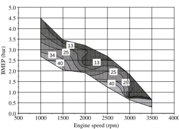
Figure 8. CAI brake specific HC emissions (g/kWh).
According to Fig. 7, levels of CO emissions are very high at 1000 rpm, possibly due to the low speed of the intake charge which adversely affects in-cylinder motion, impairing the mixing process. This could possibly lead to the formation of a localized fuel-rich zone in the cylinder and, therefore, to increased CO production. As the speed goes up, CO emissions fall drastically and increase again around 2500 rpm, when the engine operation becomes less stable at λ = 1. Above this speed, the engine could
not run anymore with λ < 1.05, a fact which explains the very low
values of CO at the higher speeds. At the top speed of 3500 rpm, CO emissions increase once again, especially at the low load region. This is expected since the engine was approaching the misfire limit. At any given speed it was observed that CO decreases with increased load.
Regarding unburned hydrocarbons, Fig. 8 shows that HC emissions decrease with increased load, for any given speed. Keeping load constant and increasing speed also helps to reduce HC emissions, suggesting that for these two conditions combustion tends to be more complete. This is expected since with increased load and speed the in-cylinder temperatures are higher, thus reducing flame quenching at the cylinder walls and crevices.
Figures 9 to 12 show a comparison between the brake specific results of CAI combustion operation in this engine and SI combustion operation of the standard production gasoline engine.
In Fig. 9, it can be seen that BSFC is reduced over the whole CAI operation and tends to improve with increased speed and reduced load. The improvements in BSFC are mainly due to the
almost absence of pumping losses at part load. Therefore, as the load approaches the lower limit, the SI engine has to operate with more throttling, impairing BSFC in comparison to the CAI engine. Moreover, the fact that CAI combustion is very fast, with nearly constant volume heat addition, also leads to improvements in fuel consumption due to a more efficient thermodynamic cycle.
B
M
E
P
(
b
ar
)
0.0 0.5 1.0 1.5 2.0 2.5 3.0 3.5 4.0 4.5 5.0
Engine speed (rpm)
500 1000 1500 2000 2500 3000 3500 4000 1
-2
-5 -8
-8
-11 -11
-14 -14
-17 -20
-20
Figure 9. Change in BSFC (%) with CAI combustion.
B
M
E
P
(
b
a
r)
0.0 0.5 1.0 1.5 2.0 2.5 3.0 3.5 4.0 4.5 5.0
Engine speed (rpm)
500 1000 1500 2000 2500 3000 3500 4000 -99
-99 -99
-88
-95 -97
Figure 10. Change in BSNOx (%) with CAI combustion.
B
M
E
P
(
b
ar
)
0.0 0.5 1.0 1.5 2.0 2.5 3.0 3.5 4.0 4.5 5.0
Engine speed (rpm)
500 1000 1500 2000 2500 3000 3500 4000 30
-10 -30 -50 -50
-70 -70 -90
Figure 10 shows the advantages of CAI combustion in NOx reduction. Over the whole speed range, NOx emissions were dramatically reduced up to 99%. This is due to the characteristic low CAI combustion temperature.
Figure 11 demonstrates that, apart from the 1000 rpm region, CO is greatly reduced over the remaining CAI range. It has a little increase at 2500 rpm, when the engine starts to be less tolerant to
λ = 1 and then falls again thereafter.
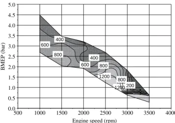
Unlike the other pollutants, HC emissions, however, are much higher with CAI than with SI combustion, as can be seen in Fig. 12. The reason for that is the low combustion temperature achieved with CAI which leads to flame quenching at the walls. Nevertheless, HC emissions are far to be the worst concern since they can easily be treated by a conventional and low cost 3-way catalytic converter.
B
M
E
P
(
b
ar
)
0.0 0.5 1.0 1.5 2.0 2.5 3.0 3.5 4.0 4.5 5.0
Engine speed (rpm)
500 1000 1500 2000 2500 3000 3500 4000 1200
1200 600
600 400 400
200 800
800
800
Figure 12. Change in BSHC (%) with CAI combustion.
Conclusion
CAI combustion has been achieved on a conventional 4-stroke, 4-cylinder gasoline engine with substantially original components, having only the camshafts replaced for units suitable for NVO. A reasonable range of load and speed could be achieved. When operating under CAI combustion, significant BSFC and emissions reduction could be achieved. This was especially important in the case of NOx emissions which were showed up to 99% reduction.
The following conclusions could be drawn:
Engine torque output (load) can be controlled by the amount of residuals trapped in the cylinder using variable valve timing and NVO. The higher the residual fraction, the lower is the torque output.
Load has a determinant effect on CAI combustion. At high loads, CAI combustion starts earlier and completes faster; combustion temperature, exhaust temperature, peak pressure and maximum pressure rise are at their maximum. Speed also has a noticeable effect for it tends to reduce emissions and increase BSFC, mainly due to friction. At high speeds, heat loss and PMEP are lower. FMEP, however, increases and offsets the advantages of the others, impairing BSFC.
For the majority of the CAI range, NOx emissions were ultra-low, mainly due to the low in-cylinder temperatures caused by the high residuals rate.
The pumping losses caused by the recompression loop due to NVO strategy are negligible.
To improve the CAI load range whilst still keeping the high dilution rate, forced induction could be a good alternative since it would enable a bigger inducted charge despite of the low lift camshafts.
CAI load and speed range could be further extended by using a more variable valve train.
CAI combustion is almost self-controlled. Variations and instabilities on in-cylinder conditions can affect the results, making combustion control one of the challenges of CAI combustion. New systems with direct cylinder pressure feedback seem to be the way forward.
Acknowledgements
The authors would like to thank Ford and Mr. Tabrez Mughis for all the information support during this research. They are particularly grateful for the Brazilian Government (Capes) to provide Mr. Martins with the financial support as part of his PhD degree study at Brunel University.
References
Christensen, M., Hultqvist, A., Johansson, B., 1999, “Demonstrating The Multi Fuel Capability of a Homogeneous Charge-Compression Ignition Engine with Variable Compression Ratio”, SAE Paper 1999-01-3679.
Christensen, M., Johansson, B., 2000, “Supercharged Homogeneous Charge Compression Ignition (HCCI) With Exhaust Gas Recirculation and Pilot Fuel”, SAE Paper 2000-01-1835.
Lavy, J., Dabadie, J.C., Angelberger, C., Duret, P., Willand, J., Juretzka, A., Schaflein, J., Ma, T., Lendresse, Y., Satre, A., Schulz, C., Kramer, H., Zhao, H. and Damiano, L., 2000, “Innovative Ultra-low NOx controlled
auto-ignition combustion process for gasoline engines: the 4-SPACE project”, SAE paper 2000-01-1873.
Law, D., Allen, J., Kemp D. and Williams, P., 2000, “4-Stroke Active Combustion (Controlled Auto-Ignition) Investigation using a Single Cylinder Engine with Lotus Active Valve Train (AVT)”, International Conference on 21st Century Emissions Technology, C588/006/2000, IMechE.
Li J., Zhao, H. and Ladommatos, N., 2001, “Research and development of controlled auto-ignition (CAI) combustion in a four-stroke multi-cylinder gasoline engine”, SAE paper 2001-01-3608.
Martins, M. and Zhao, H., 2007, “Experimental Studies of a 4-Stroke Multi-Cylinder Gasoline Engine with Controlled Auto-Ignition (CAI) Combustion”, SAE Paper 2007-01-2609.
Milovanovic, M., Blundell, D., Pearson, R., Turner, J. and Chen, R., 2005, “Enlarging the Operational Range of a Gasoline HCCI Engine by Controlling the Coolant Temperature”, SAE Paper 2005-01-0157.
Najt, P.M., Foster, D.E., 1983, “Compression-ignited homogeneous charge combustion”, SAE paper 830264.
Noguchi, M., Tanaka, Y., Tanaka, T. and Takeuchi, Y., 1979, “A Study on Gasoline Engine Combustion by Observation of Intermediate Reactive Products during Combustion”, SAE Paper 790840.
Olsson, J. and Johansson, B., 2001, “Boosting for High Load HCCI”, SAE Paper 2004-01-0940.
Olsson, J., Tunestal, P., Ulfvik, J. and Johansson, B., 2003, “The Effect of Cooled Egr on Emissions and Performance of a Turbocharged HCCI Engine”, SAE Paper 2003-01-0743.
Onishi, S., Hong Jo, S., Shoda, K., Do Jo, P. and Kato, S., 1979, “Active Thermo-Atmosphere Combustion (ATAC) – A New Combustion Process for Internal Combustion Engines”, SAE Paper 790501.
Stanglmaier, R., Roberts, C., 1999, “Homogeneous Charge Compression Ignition (HCCI): Benefits, Compromises and Future Engine Applications”, SAE Paper 1999-01-3682.
Thring, R.H., 1989, “Homogeneous Charge-Compression Ignition (HCCI) Engines”, SAE Paper 892068.
Wang, Zhi, Wang, Jian-Xin, Shuai, Shi-Jin, Tian, Guo-Hon, An, Xinlian and Ma, Qing-Jun, 2006, “Study of the Effect of Spark Ignition on Gasoline HCCI Combustion”, Proceedings of the I MECH E, Part D Journal of Automobile Engineering, Vol. 220, No. 6, pp. 817-825.
Yap, D., Megaritis, A. and Wyszynski, M., 2005, “Effect of Inlet Valve Timing on Boosted Gasoline Hcci with Residual Gas Trapping”, SAE Paper 2005-01-2136.
Yap, D., Wyszynski, M., Megaritis, A. and Xu, H., 2005, “Applying boosting to gasoline HCCI operation with residual gas trapping”, SAE Paper 2005-01-2121.