Abstract— This paper presents the design of broadband two way equal power divider in microstrip medium with defected ground structure suitable for broadband communication systems. Quarter wave broadside coupled lines are used in the place of conventional transformers widely used in the popular Wilkinson power dividers. The proposed power divider structure takes the advantage of top and bottom layers of the microstrip medium to create broadside coupled line configuration using defected ground plane. The floating conductor in the bottom layer plays a critical role in achieving the band select characteristics. Experimental results of two way equal power divider designed using the proposed structure has been verified against the full wave simulations. The isolation between the paths is more than 20dB and the return loss at each port is better than 15dB across the desired band of 3GHz to 8GHz.
Index Terms—Microstrip, Power divider, Broadband, Wilkinson
I. INTRODUCTION
Emerging applications of radio frequency and microwave technologies demand miniaturized
broadband components that accommodate multiple functionalities and high performance at low cost.
There has been a paradigm shift in the design and development of microwave systems recently. A
definite emphasis can be observed towards broadband systems as opposed to narrowband systems.
Microwave broadband power dividers find applications in modern High data rate wireless
communications, Microwave imaging systems, Software Defined Radio (SDR), Cognitive Radio,
Ultra Wide Band (UWB) radio etc. Broad band power dividers are used for distributing or tapping
signals in various radio frequency and microwave communication subsystems. Broad band Power
dividers having different structures are reported in [1]-[12] by researchers. In [1]-[2], design of
broadband power dividers is reported using Lange couplers. Broadband frequency response is the
advantage of Lange coupler, but wire bonding is the critical issue which limits the highest frequency
of operation. Power divider with wide operating bandwidth is reported in [3]-[7] using N stage
transformers. Multi stage transformers are easy to design and occupy more size in realization. Non
uniform directional couplers are used for the construction of ultra wide band power divider in [8] and
this also requires more space for the implementation. Though 3dB couplers based on left handed
materials offers broad bandwidth, these circuits still need more space [9]. In [10], ultra wide band
power divider with good isolation and sharp roll off is designed using short circuited stubs and
Broadband Equal Power Divider
D. Packiaraj, M. Ramesh
Central Research Laboratory, Bharat Electronics Limited, Bangalore, India , [email protected]
A. T. Kalghatgi
lines, a novel two way broadband equal power divider is reported in this paper using defected ground
microstrip medium. This power divider can be treated as modification to the one in [12] reported by
authors with an offset broadside coupled lines replaced by a symmetrically coupled lines to achieve
equal power division. In the proposed structure, floating conductor is created in the ground plane of
microstrip to achieve broadside coupling with the quarter wave transmission lines in the top layer.
Symmetrical broadside coupled lines have been used as the key element to construct equal broadband
power divider. The power divider has several advantages such as size compactness, inherent band
pass characteristics and fabrication ease. The construction of the proposed broadband equal power
divider is explained in Section II. Experimental results of the designed power divider are
demonstrated in Section III. Section IV concludes the present paper.
II. TWO WAY BROADBAND 3DB POWER DIVIDER
Defected ground microstrip structure has been used to design broadband equal power divider with
90% bandwidth. The specifications of the broadband two way equal power divider are given below.
Frequency of operation : 3GHz to 8GHz
Power division : Equal (3dB)
Isolation between the paths : more than 20dB
Height of the substrate ‘h’ : 0.78mm
Permittivity‘ εr’ of the substrate : 2.17.
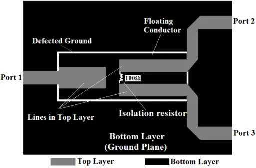
Fig. 1 depicts the proposed broadband equal power divider. The overall structure is different from the
conventional Wilkinson power divider. This structure equally divides the power over wide frequency
band through tight coupling achieved using broadside coupled lines. The power divider is constructed
on soft substrate having thickness of 0.78mm, permittivity of 2.17 and loss tangent of 0.01. It was
studied from the simulations[13] that dimensions (length and width of lines) of the power divider will
be smaller for high permittivity substrates, when compared to the low permittivity substrates.
Figure 1. Proposed broadband equal power divider
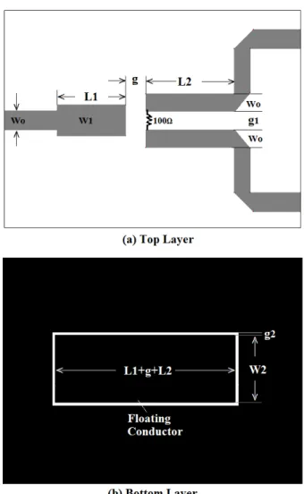
As shown in Fig. 2, transmission lines in the top layer and the floating conductor in the ground plane
constitute broadside coupling. The center frequency of the power divider is 5.5GHz and broad side
coupled lines are quarter wave long at 5.5GHz. Lengths L1, L2 and L1+g+L2 can be varied to alter
the center frequency. L1 and L2 are quarterwave long and L1+g+ L2 are half wave long at the center
frequency of operation. Dimensions of the floating conductor and spacing between the coupled lines
‘g1’ control the coupling of power between the arms. For the proposed power divider, Maximum fractional bandwidth of 110% can be achieved for the wider floating conductor(7mm) and minimum
fractional bandwidth of 10% can be achieved for narrower floating conductor(2mm). No power
division occurs for the uniform ground(no floating ground). In the design, a 100Ω resistor is placed
between the coupled lines in the top layer as shown in Figure 2 to achieve good isolation between the
output ports.
The proposed two way equal power divider was simulated using ‘IE3D’ from Mentor graphics [13]
and the results are shown in Fig. 3. It is clear from the results that the operating frequency band is from
3 GHz to 8GHz (90%). It is observed from the simulations that the proposed power divider performs
the integrated actions of band pass filter and power divider. Physical dimensions of the power divider
TABLE I. DIMENSIONS OF TWO WAY EQUAL POWER DIVIDER
Dimensions Values(mm)
Wo 2.4
W1 4
L1 8.65
L2 8.9
g 2.5
g1 2.25
g2 0.3
W2 6
III. EXPERIMENTAL RESULTS
Photographs of assembled broadband two way broadband equal power divider is shown in Fig. 4.
Standard procedure of printed circuit board (PCB) fabrication has been followed to manufacture this
power divider. Edge mount PCB connectors are used at the input and output. The input and output
lines along with isolation resistor can be seen in Fig. 4a. Fig. 4b shows the floating rectangular
conductor formed in the bottom layer. The assembled power divider has been tested using vector
network analyzer (VNA). Fig. 5 shows the measured power division and input return loss
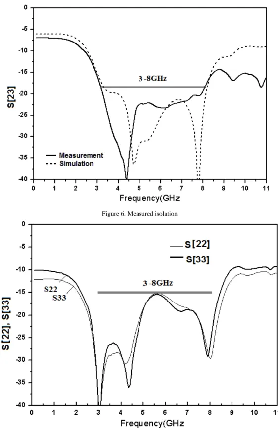
characteristics of the power divider. Measured results of isolation and output return losses are shown
in Figs 6 and 7 respectively. Measured results show that proposed power divider exhibits broadband
frequency characteristics(3GHz to 8GHz). Measured insertion loss of the equal power divider is
0.2dB and the amplitude variation between the ports is within ± 0.2dB. The isolation between the
ports is more than 20dB. The input/output return loss of the power divider is better than 15dB. It is
observed that experimental results are closely reasonable with the EM simulation results. The power
divider measures length of 39mm and width of 35mm. Another aspect of the proposed power divider
is that floating conductor should not contact with any metal surface of the system where it is being
used and clearance or provision has to be made in the system to take care of this. If the floating
conductor contacts directly with any metal surface, the bandwidth of the power divider shrinks based
Figure 4. Photograph of assembled equal power divider. a)Top layer, b)Bottom layer
Figure 6. Measured isolation
has been manufactured and tested to verify the electrical performances. The coupled power is 3.2dB ±
0.2dB over 3GHz to 8GHz at the output. The return loss at all the ports is better than 15dB. The
measured isolation between the output ports is more than 20dB over the required frequency band. The
measured results are in good agreement with the analytical and EM simulation results.
ACKNOWLEDGMENT
Authors thank Sri Mahesh V, Chief Scientist of Central Research Laboratory-BEL, Bangalore
and Management of Bharat Electronics Limited, India for their support and guidance to carry out this
research work.
REFERENCES
[1] D.M. Pozar, Microwave Engineering, Addision-wesley, 1990.
[2] G. Matthaei, G. L. Young, and E. M. T. Jones, Microwave Filters, Impedance Matching Networks and Coupling structures, Artech, 1985.
[3] R. E. Collin, Theory and design of wideband multisection quarterwave transformers, Proc. IRE, Vol. 43, No 2, pp. 179–185, 1955. [4] E. J. Wilkinson, An N-way hybrid power divider, IEEE Trans. Microwave Theory Tech, Vol. 8, No 1, pp. 116–118, 1960
[5] Y. Sun, and A. P. Freundorfer, Broadband Folded Wilkinson Power Combiner/Splitter, IEEE Microw. Wireless Compon.Lett, Vol. 14, No. 6, pp. 295-297, 2004.
[6] J. P. Shelton, J. Wolfe, and R. C. Wagoner, Tandem couplers and phase shifters for multioctave bandwidth, Microwaves, 1965, pp. 14–19.
[7] J. H. Cho, H. Y. Hwang, and S. W. Yun, A design of wideband 3- dB coupler with N-section microstrip tandem structure, IEEE Microw. Wireless Compon.Lett, Vol. 15, No. 2, pp. 113–115, 2005.
[8] S. Uysal and H. Aghvami, Synthesis, Design and Construction of Ultra-Wideband Nonuniform Directional couplers in Inhomo-geneous Media, IEEE Trans. Microwave Theory Tech, 1989, Vol. 37, No. 6, pp. 969-976.
[9] S. G. Mao, and M. S. Wu, A novel 3-dB directional coupler with broad bandwidth and compact size using composite right/lefthanded coplanar waveguides," IEEE Microw. Wireless Compon.Lett, Vol. 17, No. 5, pp. 331-333, 2007.
[10] S.W. Wong, and L. Zhu, Ultra-wideband power dividers with good isolation and improved sharp roll-off skirt, IET Microw. Antennas Propag., Vol. 3, Iss. 8, pp. 1157–1163, 2009.
[11] A. M. Abbosh, Ultra wideband inphase power divider for multilayer technology, IET Microw. Antennas Propag., Vol. 3, Iss. 1, pp. 148–153,2009.
[12] D. Packiaraj, M. Ramesh and A. T. Kalghatgi, Band select ultra wide band unequal power splitter , Microwave and optical technology letters, Vol. 58, No. 7, pp. 1563-1566, 2016.