ABSTRACT: Amazonia-1 is a Brazilian remote sensing satellite providing mainly images, in order to observe and monitor deforestation, especially in the Amazon region. This paper describes the thermal control design, which uses passive and active concepts. The active thermal control is based on heaters regulated by software via thermistors. The passive thermal control consists of multi-layer insulation blankets and radiators, paints, surface inishes to maintain temperature level of the overall carrier components within an acceptable value. The thermal control design is supported by thermal analysis using thermal mathematical model. The temperatures and heater power are predicted for critical cases.
KEYWORDS: Amazonia-1 satellite, Satellite thermal control, Thermal mathematical model.
Thermal Control Design Conception of the
Amazonia-1 Satellite
Douglas Felipe da Silva1, Issamu Muraoka1, Ezio Castejon Garcia2
INTRODUCTION
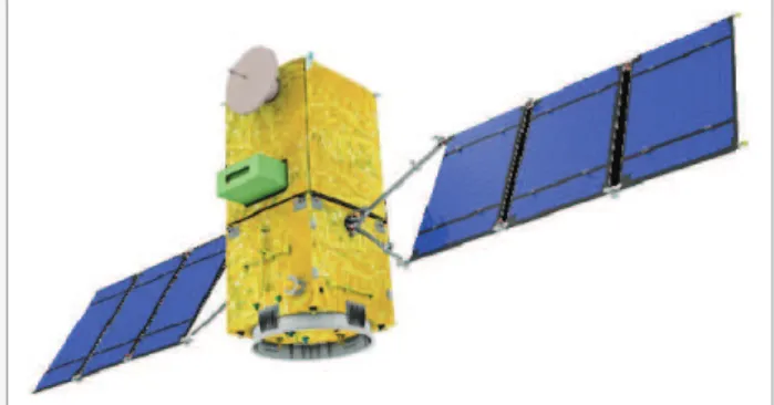
he Amazonia-1 hermal Control Subsystem (TCS) consists of active and passive thermal control elements in order to maintain the spacecrat’s components and structure within a controlled range of temperature throughout the mission of the spacecrat, from the Beginning of Life (BOL) to the End of Life (EOL). he payload equipment, the propulsion subsystem components and batteries, along with their operational requirements, are the main drive to develop Amazonia-1 thermal control design and analysis. he Amazonia-1 mission’s main goal is to provide image data, improving the deforestation monitoring capability in the Amazon region. he use of a new instrument called Advanced Wide Field Imager (AWFI) with a 40-meter spatial resolution on board will improve the capability of the system (Scaduto et al., 2010). he current Wide Field Imager (WFI) camera acquires images in two spectral bands, while in the AWFI the images will be acquired in four bands. Figure 1 presents the satellite.
he remote sensing Amazonia-1 satellite is the irst mission to use the Multi-Mission Platform (MMP) concept developed by the Instituto Nacional de Pesquisas Espaciais (INPE), coordinated
1. Instituto Nacional de Pesquisas Espaciais – São José dos Campos/ SP – Brasil 2. Instituto Tecnológico de Aeronáutica – São José dos Campos/ SP – Brazil Author for correspondence: Douglas Felipe da Silva | Instituto Nacional de Pesquisas Espaciais – Av. dos Astronautas, 1.758, São José dos Campos/SP | CEP: 12.227-010 |
Brazil | Email: [email protected]
Received: 01/13/2014 |Accepted: 04/17/2014
by Brazilian Space Agency (AEB). he MMP platform concept provides capability to support a variety of low Earth orbit missions using the same basic three-axis stabilized platform, with diferent payload instruments (Santana et al., 2012). he MMP main design goal is modularity, allowing separated integration from the satellite payload module. his provides independent design, construction and test of each module before payload-to-MMP integration and inal compatibility tests.
here is an extended amount of works available in the literature about satellite thermal control and, for instance, the handbook of Gilmore (2002), as well as the text books of Karam (1998) and Messeguer et al. (2012), are some of the best work presented.
FEATURES OF THE AMAZONIA-1
SATELLITE
A few salient features of Amazonia-1 satellite are as follows:
• Overall dimensions of the main body: 2,200 x 950 x 950 mm;
• Mass: About 500.0 kg;
• Orbit: Sun-synchronous, 752.4 km high, 98.405° inclination and passage time 10:30 a.m.;
• Structure: Aluminum honeycomb structure;
• Power: 420 W (average), InGAP/InGaAs/Ge solar panels, lithium ion battery;
• Stabilization: 3 axis stabilized;
• Mission life: 4 years.
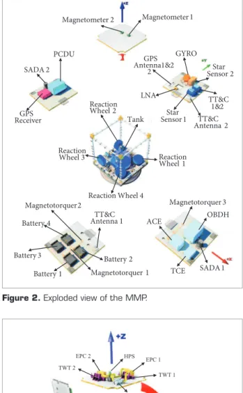
he exploded view of the MMP is presented in Fig. 2, and Fig. 3 presents the payload.
During nominal operation mode, the -Y face will be always pointed to Earth. In emergency mode, the satellite attitude control will point -Z, facing the Sun, in order to warm up the propulsion subsystem elements, and two rotations per orbit will be imposed around the Z axis (in negative direction), in order to distribute external heat loads equally on the lateral panels.
CONSTRAINTS AND
REQUIREMENTS TO TCS
he Amazonia-1 TCS shall provide a thermal environment which ensures reliable performance of all components during all mission
phases, minimizing the thermal control mass and heater power budgets. he main functions of the Amazonia-1 thermal control are:
Battery 2
Magnetotorquer 1 TT&C
Antenna 1 ACE OBDH
SADA 1 TCE
TT&C 1&2 GYRO
Star Sensor 2
LNA GPS Antenna1&2
2
GPS Receiver
PCDU
SADA 2
Magnetometer 1 Magnetometer 2
Reaction Wheel 3
Tank Reaction Wheel 2
Reaction Wheel 4
Reaction Wheel 1
Battery 1 Battery 3
Battery 4
Magnetotorquer2 Magnetotorquer 3 TT&C Antenna 2 Star
Sensor 1
Figure 2. Exploded view of the MMP.
BPF
TWT 1 TWT 2
EPC 2
EPC 1 HPS
QPSK-TX
SSR SDC
SPE 1
SPE 2
DSS
AWFI
AWDT Antenna
• To provide temperature distribution in order to have all onboard equipment operate within their designed operational temperature range, under all possible attitudes experienced during all mission phases;
• To allow the dissipation of the excess energy generated with no detrimental efect.
he Amazonia-1 thermal design conception is based on the balance of the following criteria:
• Insulate, as well as possible, the satellite of external environment. Making use of this approach, temperatures are less sensitive to the external radiation and the satellite can perform better during all mission stages. Radiators are used in order to reject internal heat dissipation;
• Minimization of thermal gradients in the satellite by using high emittance coatings on the majority of the internal surfaces (equipment and structural parts) and improving the conductive coupling between equipment and mounting panels, through thermal interface iller materials;
• For AWFI, batteries and propulsion components, which have operational temperature limits quite diferent from the remaining equipment in the satellite, the paragraph above is not applicable. hese components shall be thermally insulated — by radiation and conduction — from the
satellite, having their temperatures controlled individually by heaters;
• Insulate the equipment placed in direct view to space from the space environment. his is necessary in order to avoid large temperature luctuation on these equipment, through illuminated and eclipse periods;
• Insulate MMP from payload module, considering the
premise that the MMP is a multi-mission platform and its thermal design shall be qualiied for any payload;
• he electrical power allowance for heaters shall not exceed 30 W during mission nominal modes and 60 W during emergency mode;
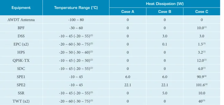
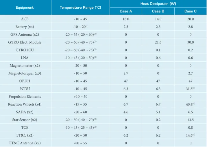
• he temperature limits (operational and non-operational) and the heat dissipation for all equipment are disposed in Table 1 (payload) and Table 2 (MMP). he cases in these tables will be described further on in “Cases under evaluation”.
THERMAL CONTROL SYSTEM USED
IN AMAZONIA-1
As explained before, in order to minimize temperature gradients, all internal surfaces of the satellite are coated with
Table 1. Payload equipment temperature limits and heat dissipation.
Equipment Temperature Range (°C)
Heat Dissipation (W)
Case A Case B Case C
AWDT Antenna -100 ~ 80 0 0 0
BPF -30 ~ 60 0 0 10.0(1)
DSS -10 ~ 45 (-20 ~ 55)(2) 0 3.0 3.0
EPC (x2) -20 ~ 60 (-30 ~ 75)(2) 0 0.1 1.5(3)
HPS -20 ~ 50 (-30 ~ 60)(2) 0 0 3.2(1)
QPSK-TX -10 ~ 45 (-20 ~ 50)(2) 0 0 12.0(1)
SDC -10 ~ 45 (-20 ~ 55)(2) 0 0 4.0(1)
SPE1 -10 ~ 45 6.0 6.0 90.9(4)
SPE2 -10 ~ 45 22.1 22.1 101.6(4)
SSR -10 ~ 45 (-20 ~ 55)(2) 0 5.0 10.0
TWT (x2) -20 ~ 60 (-30 ~ 75)(2) 0 0 40(3)
(1)15 min of operation in illuminated period; (2)non-operational temperature range; (3)15 min of operation in illuminated period (only main unit; the redundant one is on
high emittance black paint. All external surfaces are wrapped with 20 layers of Multilayer Insulation (MLI) blankets with areas available for positioning the radiators. In order to reduce heater power consumption during emergency mode, the internal face of the adapter cylinder, positioned at the MMP -Z panel, is kept in bare aluminum, as well as the areas of the -Z panel which are out of the cylinder circle.
The propulsion components were dealt with different approach since they shall be kept at a temperature range from +10 °C to +50 °C. he lower limit of +10 °C is so to avoid hydrazine freezing. Considering that the lower temperature limit of the propulsion subsystem is considerably higher than those of the remainder MMP components, the thermal design was set according to the following baseline:
• Radiative insulation of all components (except thrusters) wrapping them with 15 layers of MLI blanket;
• Conductive insulation of all attachment points with the mounting panel using iber glass-epoxy composite washer;
• Electrical heating using skin and spiral heaters on all components.
A total of seven heater circuits (four main and three redundant ones) are installed on the propulsion components, using correspondently 7 switched heater lines. All lines are controlled by ON/OFF commands from the On Board Data Handling (OBDH), which uses the thermistor telemetry as input data. he thermistors which will be used are space qualiied, interchangeable, NTC type with a resistance of 10 kΩ at 25 °C, and manufactured by Measurement SpecialtiesTM.
he batteries panel also received speciic design since their range, 0 to 20 °C, is narrower than most of the electronic equipment in the satellite (-10 °C ~ 45 °C). he concept is to couple the battery packs to the mounting panel and to use
Table 2. MMP equipment temperature limits and heat dissipation.
Equipment Temperature Range (°C)
Heat Dissipation (W)
Case A Case B Case C
ACE -10 ~ 45 18.0 14.0 20.0
Battery (x4) -10 ~ 20(1) 2.3 2.3 2.8
GPS Antenna (x2) -20 ~ 55 (-20 ~ 60)(2) 0 0 0
GYRO Elect. Module -20 ~ 60 (-40 ~ 75)(2) 0 21.6 30.0
GYRO ICU -20 ~ 60 (-40 ~ 75)(2) 0 0.1 0.2
LNA -10 ~ 45 (-20 ~ 50)(2) 0 0.6 0.6
Magnetometer (x2) -20 ~ 50 0 0 0
Magnetotorquer (x3) -10 ~ 50 2.7 0 2.7
OBDH -10 ~ 45 47 47 47
PCDU -10 ~ 45 6.3 6.3 31.8(3)
Propulsion Elements +10 ~ 50 0 0 0
Reaction Wheels (x4) -15 ~ 55 6.7 6.7 40.4(4)
SADA (x2) -20 ~ 60 4.6 5.1 6.5
Star Sensor (x2) -20 ~ 50 (-40 ~ 70)(2) 0 0.2 13.5
TCE -10 ~ 45 (-25 ~ 45)(2) 0 0 0.8
TT&C (x2) -20 ~ 50 6.2 6.2 14.6(5)
TT&C Antenna (x2) -80 ~ 55 0 0 0
(1)At mounting panel; (2)Non-operational temperature range; (3)Operation in illuminated period; (4)6 min of operation in illuminated period; (5)15 min of operation in
this panel as a radiator. he mounting panel is insulated, conductively (through fiber glass-epoxy washers) and radiatively (15 layers of MLI blanket), from the other parts of the satellite.
In order to avoid the temperature at battery panels below -10 °C, heaters are placed at the panel, near the batteries’ feet. he temperatures at the panel are monitored by four thermistors, placed near the heaters. The heater circuits will be activated by ON/OFF commands from the OBDH. he main circuit will turn on at -8 °C and turn of at -6°C, while the redundant ones will turn on at -10 °C and turn of at -8 °C. he temperature refers to the lowest value among the four thermistors.
The AWFI has autonomous thermal control, and it is wrapped with a MLI blanket and conductively insulated from the mounting panel through washers. Also, it has its own radiator and dedicated heaters. Since its thermal control is independent from the satellite (Scaduto et al., 2010), in this global analysis, its temperature was considered to be between 15 °C and 20 °C. The thermal optical properties of coatings used in the satellite are presented in Table 3.
VERIFICATION OF DESIGN
BY THERMAL MATHEMATICAL
MODELING
The thermal modeling is based on a nodal or lumped parameter method. In this method, the satellite is divided in a number of regions, assumed isothermal, which is called nodes. hese nodes exchange heat among each other by conduction and radiation, and with space by radiation. Also, they can receive heat loads from external sources or from electronic
components. he temperature of each node is the result of these interactions. he governing equation is the energy equation which consists of transient, conduction, and radiation terms, plus boundary conditions (solar radiation, albedo and Earth radiation), as a source term. his equation can be written as presented in Eq. (1) (Karam, 1998):
(1)
Where the thermal mass is mcp [J/K]. he external loads are
QS, QA, and QE[W], while internal heat dissipation is QD[W].
he conduction and radiation exchange factors are represented by Kij[W/K] and Rij[m-²], respectively. he Stefan-Boltzmann
constant is σ[W/m²/K4], and Tiand Tj[K] are the temperatures of nodes i and j, respectively.
he temperatures have been calculated in transient regime, considering variations on external heat loads and equipment heat dissipation proiles. he model was built using the C&R Technologies ThermalDesktop/Radcad - SINDA/FLUINT thermal sotware package, and details of this package can be obtained in Panczak et al. (1998).
The MMP is represented by 2,764 diffusion nodes and 1,698 arithmetic ones, while the payload is represented by 4,161 difusion, 1,444 arithmetic and 2 boundary nodes. hus, the whole model is composed by 6,925 difusion nodes, 3,142 arithmetic nodes and 2 boundary ones (total of 10,069 nodes). he arithmetic nodes are used in order to represent the MLI blankets, which have small mass, since these elements have very low thermal capacitances and respond almost instantaneously to the thermal changes of environment.
The boundary nodes are used in order to represent a component with constant temperature. In this case, the equipment is the AWFI, since it has its own active thermal control and it shall operate between +15 °C and +20 °C.
Table 3. Coatings’ thermal optical properties.
Coating Emissivity (ε)
Absorptivity (α) Effective
Emissivity (εeff)
BOL EOL
Bare Aluminum 0.05 0.15 0.15
-Black Paint 0.88 0.95 0.95
-MLI 0.80 0.41 0.51 0.02
White Paint 0.94 (BOL)
-CASES UNDER EVALUATION
he design philosophy is to ind the critical cases and analyze them supposing that all other cases result in intermediate temperatures. hree critical cases are evaluated: cold, hot and emergency cases.
• Case A: Cold case represents the nominal operational mode in which minimum external heat loads (albedo: 0.34; Earth radiation: 208 W/m²; solar radiation: 1326 W/m²), minimum internal heat dissipation and BOL optical properties are considered. he orbit parameters are adopted for winter solstice, and the satellite -Y face will be pointing towards Earth;
• Case B: Hot case represents the nominal operational mode in which maximum external heat loads (albedo: 0.42; Earth radiation: 233 W/m²; solar radiation: 1418 W/m²), maximum internal heat dissipation and EOL optical properties are considered. he orbit parameters are adopted for summer solstice, and the satellite -Y face will be pointing towards Earth;
• Case C: Emergency case represents the satellite with attitude diferent from the nominal mode. In this case, the satellite -Z face is permanently oriented towards the Sun and the solar panel is oriented parallel to the -Z panel. he spin rate is two revolutions per orbit around the Z axis, in negative direction. he power consumption is minimized in this mode. Some equipment are turned of during this case and the temperature limit is the non-operation limit. he external heat loads, orbit parameters and optical properties are the same considered in case A (nominal cold case).
TEMPERATURES AND HEATERS
POWER CONSUMPTION PREDICTIONS
he temperatures have been calculated in transient condition, and the stabilization criterion was considered when the temperature variation between two consecutive orbits is less than 0.1 °C in the same orbit point, for hot case. In cold and emergency cases, it is not possible to accomplish this criterion, since heaters are required and their ON/OFF dynamic does not allow the same conditions at the same orbit point. In this case, a minimum of 15 orbits are simulated.
he extreme predicted temperatures for payload (minimum for emergency case and maximum for hot case) are shown in Fig. 4. By analyzing Fig. 4, it should be noted that the predicted range of the equipment are the extremes of the central (black solid) bar. he empty space between this bar and the other two ones (minimum limit to the let and maximum to the right) is the temperature margin of the equipment.
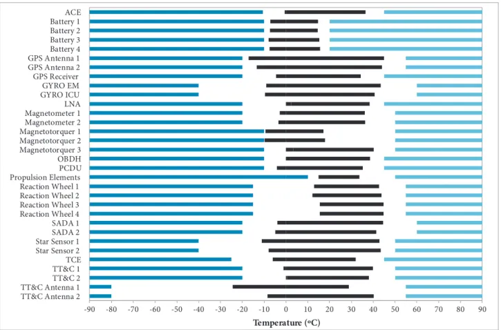
The extreme predicted temperatures for MMP are shown in Fig. 5.
All maximum temperatures were predicted with at least 5 °C of margin, and the cold ones are controlled by heaters. It should be noted that the predicted temperatures of the solar array generator exceeded the acceptable range (-80 °C to 80 °C), reaching -84.6 °C in the emergency case and 82.1 °C in the hot case. Although its temperature does not afect the satellite thermal behavior considerably, a detailed thermal analysis will be accomplished in order to satisfy its temperature requirement.
-90 -80 -70 -60 -50 -40 -30 -20 -10 0 10 20 30 40 50 60 70 80 90
TWT 2 TWT 1 SSR SPE2 SPE1 SDC QPSK-TX HPS EPC 2 EPC 1 DSS BPF AWDT Antenna
Temperature (ºC)
To achieve the temperatures presented in Figs. 4 and 5, it was necessary to determine radiators areas. he process to ind these areas, presented in Table 4, is iterative.
he average power consumption for all heaters, during cold and emergency cases, is presented in Table 5.
For the nominal cold case (Case A), the heater power consumption is within the requirement (30 W) with 25% margin,
according to U.S. Department of Defense (1982). For emergency cases, the predicted power does not comply with the requirement (60 W). his value is under review, since in emergency cases the overall power consumption is reduced and more power is available. he emergency case is thermally critical due to its distinct attitude, in which the payload module remains in the Sun shadow, and almost all equipment are turned of.
Table 4. Radiators areas.
Radiator Location
Area (m²)
MMP Payload
+X Face 0.3624 0.2356
-X Face 0.1035 0.015
+Y Face 0.24 0.1596
-Y Face 0.432 0
Total 1.1379 0.4102
-90 -80 -70 -60 -50 -40 -30 -20 -10 0 10 20 30 40 50 60 70 80 90 TT&C Antenna 2
TT&C Antenna 1 TT&C 2 TT&C 1 TCE Star Sensor 2 Star Sensor 1 SADA 2 SADA 1 Reaction Wheel 4 Reaction Wheel 3 Reaction Wheel 2 Reaction Wheel 1 Propulsion Elements PCDU OBDH Magnetotorquer 3 Magnetotorquer 2 Magnetotorquer 1 Magnetometer 2 Magnetometer 1 LNA GYRO ICU GYRO EM GPS Receiver GPS Antenna 2 GPS Antenna 1 Battery 4 Battery 3 Battery 2 Battery 1 ACE
Temperature (ºC)
Table 5. Heaters power consumption.
Heater
Power Consumption (W)
Case A Case C
Batteries
Panel 1.44 32.42
Payload
Module 12.45 44.37
Propulsion
Elements 3.69 2.85
Total 17.58 79.64
REFERENCES
Gilmore, D.G., 2002, “Spacecraft Thermal Control Handbook”, 2nd Edition, The Aerospace Corporation Press, El Segundo, CA, Vol. I.
Karam, R.D., 1998, “Satellite Thermal Control for System Engineers”, Progress in Astronautics and Aeronautics, AIAA, Cambridge, Vol. 181, pp. 274.
Meseguer, J., Pérez-Grande, I. and Sanz-Adréz, A., 2012, “Spacecraft Thermal Control”, Woodhead Publishing, Cambridge.
Panczak, T., Ring, S. and Welch, M., 1997, “A CAD-based Tool for FDM and FEM Radiation and Conduction Modeling”, Cullimore and Ring Technologies, 28th ICES Conference, SAE Paper 981577.
Santana, A.C., Martins-Filho, L.S., Duarte, R.O., Arantes Jr., G. and Casella, I.S., 2012, “Attitude Control of a Satellite by Using Digital Signal
Processing”, Journal of Aerospace Technology and Management, Vol. 4, No. 1, pp. 15-24. doi: 10.5028/jatm.2012.04014611.
Scaduto, L.C.N., Carvalho, E.G., Santos, A.R., Soares, A.L., Castellar, A., Azeka, L.A., Souza, W.M., Evangelista, S., Santos, A.G., Malavolta, A.T., Vales, L.F., Segoria, D., Santos, F.S., Candeloro, L., Almeida, M.R., Yasuoka, F.M.M., Modugno, R.G., Cartolano, R., Barbalho, S., Santos, P.A., Rebolho, D., Otoboni, J.A., Correa, Y., Stefani, M.A. and Castro Neto, J.C., 2010, “The Advanced Wide Field Imaging Camera (AWFI) for the Amazonia 1 Brazilian Satellite”, International Conference on Space Optics (ICSO), Rhodes, Greece.
U.S. Department of Defense, 1982, “Test Requirements for Space Vehicles - MIL-STD-1540B”, U.S. Air Force, Washington, D.C., USA, pp.16-17.
CONCLUSIONS AND FUTURE ACTIONS
The Amazonia-1 thermal control design and analysis were presented. This design has been verified through the use of the SINDA/FLUINT thermal analyzer, and established by using passive means and heaters. All subsystems have been in the specified temperature ranges, for nominal and emergency cases. The heater power predicted for
nominal operational cases complies with the specification, however, in an emergency case, the predicted value is beyond specification. This requirement is under review and may possibly be increased.