Analysis and behavior of steel storage drive-in racks
Arlene M.S. Freitas
a,, Flavio T. Souza
b, Marcilio S.R. Freitas
aaDepartamento de Engenharia Civil, Escola de Minas, Universidade Federal de Ouro Preto, 35400-000 Ouro Preto-MG, Brazil bInstituto Federal de Minas Gerais, Campus Congonhas, 36420-000 Congonhas-MG, Brazil
a r t i c l e
i n f o
Article history: Received 23 March 2009 Received in revised form 17 July 2009
Accepted 16 September 2009 Available online 22 October 2009
Keywords: Drive-in racks
Thin-walled perforated members Beam-to-column joints Column bases Semi-rigid joints Finite element analysis
a b s t r a c t
This work presents a general analysis of drive-in racks, evaluating the influence of each of their components on global stability. In this study, a full-scale test of a drive-in system was carried out. Finite element models were also developed to evaluate global structural stability and component influence on system behavior. The experimental and numerical results show that the connections and base plates have the most significant influence on the system’s behavior. This influence is analyzed, an equation that predicts base plate resistance is then proposed, and its results are compared with experimental and numerical results.
&2009 Elsevier Ltd. All rights reserved.
1. Introduction
Over the last few years, the use of cold-formed steel profiles has become more popular in civil engineering. This is due to many factors including, among others: (1) their low cost relative to welded and hot rolled steel profiles; (2) their versatility—they can be used in many types of structures; and (3) research advances, which have resulted in standardized design procedures. Industrial storage systems (racks) are among the most important structures made of cold-formed profiles. They are widely used due to the increasing need for rational space utilization in warehouses, factories and other facilities used to store goods. Rack members usually have perforations for assemblage, and are susceptible to the local and global instability phenomena characteristic of thin-walled structures.
There are various static and dynamic rack types to accom-modate existing space and product storage requirements. The author’s research concentrates on static systems. Static systems require forklifts to load goods onto the racks. Of the static racks, the most commonly used is the adjustable pallet rack; earlier studies[1,2,3]and standard prescriptions[4] are limited to this type. The adjustable pallet rack has transversal beams that support the pallets and improve system stability in a down-aisle direction, but such beams prevent forklifts from moving within the racks. As such, aisles are needed to give the forklifts access to
the products in the racks, improving handling of the stored goods. The disadvantage is that the aisles reduce both the space available for and density of product storage.
Another common rack type is the drive-in system, in which there is multi-level product loading in a cross-aisle direction. In contrast to pallet racks, drive-in racks are structured to permit very high storage space utilization, at the price of reduced accessibility. These racks have an operating face, to permit forklift entry, and a rear face with bracings for improved lateral stability. The absence of transversal beams in the cross-aisle direction (for forklift movement within the system) makes this system more susceptible to instability phenomena in this direction. Down-aisle stability is obtained mainly from base plate connec-tions and semi-rigid beam–column joints stiffness at the top of the structure. The buckling length in this direction is high, making the structure more unstable than the pallet racks. There are several recent works[5,6,7,8] that investigate drive-in racks, as there is a need for safe and economical structures. These studies focus on instability phenomena, structural loading effects and multiple-component global behavior.
The aim of this paper is to present a general analysis of drive-in racks, evaluating the influence of each of their components with respect to global stability. This is important and necessary research because the number of drive-in system failures is considerable, so improvement in analysis and design methods is needed.
In this study, a full-scale test of a drive-in system was carried out. Finite element models were also developed to evaluate global structural stability and component influence on drive-in system Contents lists available atScienceDirect
journal homepage:www.elsevier.com/locate/tws
Thin-Walled Structures
0263-8231/$ - see front matter&2009 Elsevier Ltd. All rights reserved. doi:10.1016/j.tws.2009.09.003
behavior. The commercial software ANSYS [9] was used for this simulation. The experimental and numerical results show that the connections and base plates have the most significant influence on system behavior. This influence is analyzed, and an equation that predicts base plate resistance is proposed, and its results are compared with experimental and numerical results.
2. Experimental analysis of the full-scale frame
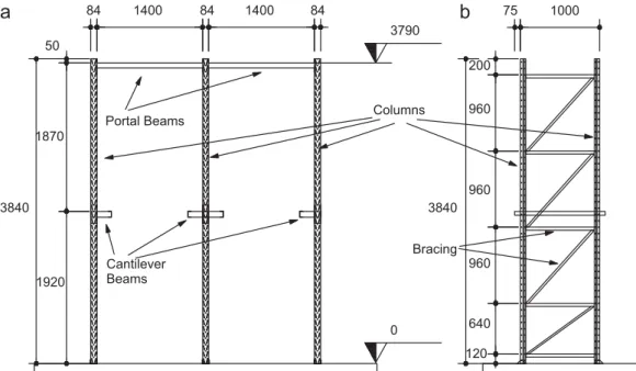
In this study, two identical commercial rack frames are tested. These structures are designed to behave as do actual structures under service conditions and are built by a Brazilian storage systems company [10]. The dimensions are determined by the available laboratory space, while simultaneously including all the instability phenomena expected in these structures. The
dimensions are presented in Fig. 1. The portal beams are
60402 and the cantilever beams are 75502 unlipped
channel sections. The columns are rack sections, as shown in
Fig. 2; these have a deliberate set of perforations along their upper level that allows fitting and bolting of beams, bracings and base plates. The bracings are 321691.5 lipped channel sections. Horizontal bracings are used on the top of the structure and spine bracings on the lateral faces. The rear face is built without spine bracings, leading to an extremely unstable condition in the lateral direction, producing conservative experimental results.
The base plates are cold-formed components bolted to the floor and columns. They are pinned in the cross-aisle direction, but have some stiffness in the down-aisle direction, provided mainly by base plate thickness and its fixation to a concrete floor. In this test, the base plates are bolted to concrete blocks that are fixed in the reaction slab and that represent the concrete floor of a warehouse.
In the test, vertical loads are applied to simulate pallet loading, and horizontal loads are applied on the frame top to induce the instability phenomena. This latter application represents eventual lateral loads, such as impacts from vehicles, wind or other loads. The vertical loads are provided by compressive jacks and are applied simultaneously to both rack aisles. They are applied to the cantilever beams by a pinned system of reaction beams that distribute the loads uniformly, simulating the pallet effect and
avoiding local effects in the cantilever beams. The horizontal loads are applied by a rope and pulley system. Barrels containing specific amounts of water are added to provide a proportional balance between vertical and horizontal loading during all test stages. The amounts of water are chosen to represent 1.5% of total vertical load applied to the system in each load step. This percentage is chosen based on RMI standards for pallet racks.
Fig. 3shows the loads applied to the system.
The horizontal displacement in the structure’s top was chosen as the parameter to evaluate system stability. Linear variable displacement transducers (LVDT), positioned at the tops of four columns, simultaneously record measurements. Cantilever beam behavior is evaluated by strain gauges (EER), and displacement transducers are used to verify their displacement, the fixity of concrete block in the reaction slab and the occurrence of local phenomena in the columns. Three HBM Spider8 devices and a PC are used for LVDT and EER data acquisition.
During experimental tests, the columns were free of any local phenomena. The cantilever beams, which bear all vertical loads imposed in the system, determine structural failure based on their
Cantilever Beams
Portal Beams Columns
Bracing
1400 1400
84
3840 3840
1870
1920 50
3790
75
200
960
960
960
640
120 0
84 84 1000
Fig. 1.Drive-in system dimensions.
40 70
84
32
20 26
2,65 Web
Flange
Rear Flange
Stiffener
observed local phenomena. Due to elevated load concentration and shearing effects, displacement in their webs is observed, suggesting that their collapse is due to web crippling[8], as shown inFig. 4.
The experimental test results are used to evaluate the global behavior of the system and to analyze the interaction among its various components. This evaluation is carried out through numerical analysis of the system and its components. The numerical analyses of the components, notably base plates, are carried out to evaluate their stiffness. The drive-in model has its beam–column semi-rigid connection stiffness from previous experimental tests[11]. Under different joint stiffness conditions, drive-in numerical analyses are carried out to determine their influence on frame behavior. This is done by comparing several finite element models with the experimental top lateral displace-ment in the drive-in system.
3. Numerical analysis of base plates
Base plate behavior is analyzed by finite element analysis, carried out with the commercial software ANSYS. The aim of this study is to observe base plate behavior under eccentric compres-sion, in order to verify its failure mode, stiffness and moment resistance. Dı´az[12]and Godley[13]have studied other layouts of base plates under similar conditions. Dı´az [12] developed a computational procedure based on the finite element program ANSYS that was validated against experimental models giving a good agreement. A similar model was used in this study.Fig. 5
shows the base plate under analysis, and its component names. The finite element model consists of a stub column fixed in the base plate. The length of the column is chosen in order to avoid its flexural collapse. The fixity between base plate and column, made by bolts, is represented by coupling translational node degrees of freedom in the column’s flange perforation region and base plate lips.
The base plate is bolted to the floor. The translational displacements in the hole region are then restricted in all directions. In other nodes of the base plate foot, the effects of eccentricity must be considered. Thus, in one part of the base plate foot, there is compression, while in the other, the foot tends to get away from the floor, due to tension effects. In the region under compression, the vertical node displacements are re-stricted, to simulate the concrete floor effect. The other nodes are considered unconstrained. The compressed and tensioned regions of the base plate foot are determined preliminarily by finite element analyses.
The finite element model is presented inFig. 6. The base plate, the column and the load plate, used for uniform compression in all load stages, are modeled by the SHELL181 element. This element is suitable for analyzing thin shells that have the large deformation capability expected in this analysis. This element can be used with three or four nodes, each having six degrees of freedom. In this study, four node elements are chosen, due to the accuracy in their results.
Horizontal Load
Vertical Load
Reaction Beams
Reaction Beam
Pin Cantilever Beam Reaction Beams Pin
Fig. 3.Loading scheme used in tests.
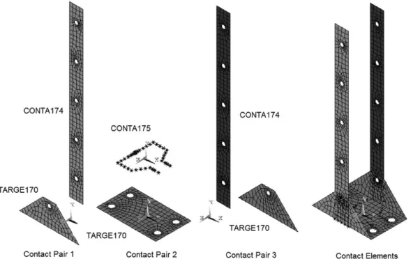
Contact between the base plate and the column is fundamental in connection behavior. This modeling is complex, because there is contact between the areas in the column flanges and the base plate lips, and between the nodes at the end of the column and the area in the base plate foot. Three contact pairs working independently are created. These are shown inFig. 7. Contact pairs 1 and 3 represent the interaction between the column flanges and the base plate lips. These contact pairs use TARGE170 and CONTA174 elements. TARGE170 elements define the surface that contact elements overlay. CONTA174 elements define the contact surface, therefore these contact pairs are suitable for modeling contact between parallel surfaces. The contact algorithm adopted for these contact pairs is the internal multipoint constraint (MPC). These are quadrilateral three-dimensional elements with four nodes. Contact pair 2 simulates the interaction between the column end nodes and the base plate foot. The contact elements used are TARGE170 and CONTA175, which represent the contact
between a node and a surface; as such, this contact pair must be used in contact between normal surfaces. The contact algorithm chosen for this contact pair is the augmented Lagrangian, and 0.35 is the allocated friction coefficient.Table 1summarizes the elements used in the base plate model.
The load is applied in two steps. First, a compression load is applied in such a way that uniform pressure is distributed on the load plate. Numerical analysis shows that this load has consider-able influence on base plate behavior, as observed by Godley[13]: the greater the compression load, the greater the base plate stiffness. So, for this research, the chosen compressive load is that achieved in the experimental test, permitting comparison be-tween the numerical and experimental results. Second, a lateral displacement load is applied to the column in the direction that the stiffness determination is needed, i.e., the down-aisle direc-tion of the entire frame. This displacement is applied in various sub-steps, to evaluate base plate behavior during its loading history. In each sub-step, the reaction induced by the base plate subject to lateral displacement is recorded, and from this result, the moment applied in that displacement stage is determined. This value is important to determine the base plate momentrotation relationship.
Large displacement and plasticity effects are included in the model. The steel mechanical properties are added using a multilinear stress–strain diagram, determined experimentally
[11], with a yielding stress of fy=320.23 MPa and an ultimate stress offu=432.5 MPa.
4. Drive-in system numerical analysis
To evaluate system components, the numerical analysis of a 3-D model is carried-out by ANSYS. The columns and portal frames are built using BEAM44 elements. BEAM 44 is a uniaxial element with tension, compression, bending and torsion capabilities. It has two nodes with six degrees of freedom in each node, with translations and rotations in thex,yandzdirections. BEAM44 is chosen because it allows modeling of unsymmetrical sections, typical of columns considered in this work. The section properties needed for this element are second order moments, centroid position and area. These properties are determined with consideration of the net area, i.e., the section most reduced due to perforation[14].
Lateral and top bracings were modeled using the LINK180 element. This element uses bars with two nodes and three Fixity of
base plate and column
Fixity of base plate and floor
Lip
Foot
Fig. 5.Drive-in system base plate.
degrees of freedom in each node, with translations in thex,yandz directions. This is a simple element, and the only section datum needed is the area.
The spring element COMBIN14 is used to simulate joint stiffness. This element has wide ranging behavior, so it can be used as a torsional or longitudinal spring in 1-D, 2-D or 3-D settings. In this analysis, it is used as a 1-D torsional spring, i.e., only a torsional capability in thezdirection was considered. The behavior of portal beam joint and base plate connections are considered linear, with a constant stiffness during all load stages. Portal beam and cantilever beam semi-rigid joint stiffness (73.86 kN m/rad) is determined from previous work[11]. Base plate connection stiffness is determined by numerical analysis, as shown above. In order to evaluate the influence of connection stiffness in the overall behavior of the drive-in system, connections are simulated as semi-rigid, with the values presented above, and as pinned and fixed, as follows:
Case 01: fixed portal beam joints and bases Case 02: semi-rigid portal beam joints and fixed bases Case 03: semi-rigid portal beam joints and pinned bases Case 04: pinned portal beam joints and fixed bases Case 05: semi-rigid portal beam joints and basesFig. 8shows the 3-D model used in the analysis, the names of components and the elements used for each, and the loading scheme. Table 2 summarizes element properties. The loading scheme is the one presented above in the experimental setup. Distributed vertical loads are applied to the cantilever beams, to represent pallet loading. To represent the horizontal impacts,
concentrated forces equivalent to 1.5% of the total vertical load acting on the system are applied at the top of the structure. Large displacement effects are introduced in the model.
Comparison between the finite element model results obtained for previously described Cases 1–5 and the experimental results demon-strates how joints influence the overall behavior of drive-in racks.
Fig. 7.Contact pairs used in analyses.
Table 1
Elements used in the base plate finite element model.
Element Nodes Degrees of freedom
SHELL181 4 UX,UY,UZ,RX,RY,RZ
TARGE170 4 UX,UY,UZ
CONTA174 4 UX,UY,UZ
CONTA175 1 UX,UY,UZ
Fig. 8.Drive-in finite element model.
Table 2
Elements used in drive-in finite element model.
Element Nodes Global degrees of freedom
BEAM44 2 UX,UY,UZ,RX,RY,RZ
LINK180 2 UX,UY,UZ
5. Results
5.1. Base plate finite element model
The base plate finite element model shows the displacement and stresses developed under load conditions during the complete loading process. It is observed that in the first load step (i.e., pure compression), observed displacements and stresses are small. But in the second load step (i.e., application of a lateral displacement), the displacement and stress results change significantly from early load stages on.
The stresses in the stub column, used to simulate actual base plate service conditions, are analyzed to verify if local failure occurs. This is not observed, proving that collapse actually occurs in the base plate, thus assuring the model’s efficiency.
Fig. 9shows the displacement observed in the base plate. It is evident that the base plate foot is bent, and that one base plate lip is tensioned while the other is compressed. It can also be seen that the bending occurs about an axis aligned with the holes used to fix the plate to the floor.
Fig. 10 shows the momentrotation curve obtained in this analysis, as described below. The curve’s initial branch is linear,
and the initial stiffness is 479.78 kN m/rad. From a certain moment value, material yielding begins in the holes region, and base plate behavior changes, with progressive reduction in stiffness, until formation of an in-line plastic zone defined by the holes. Thus, plastification in the hole region can be assumed as the base plate collapses, due to high observed reduction in stiffness at this point.
5.2. Joint stiffness influence in overall drive-in system behavior
The initial base plate stiffness value presented above is introduced into a drive-in finite element model to predict the behavior of the base plate in actual service conditions. A semi-rigid base plate is assumed. Overall drive-in behavior is analyzed by comparison between numerical model and experimental results. Base plate and portal beam joint stiffnesses are modified to quantify the influence of each one, based on the comparison shown below. The simulated cases are described in Section 4.
Fig. 11shows finite element top displacement in the five cases studied along with their comparison with experimental data. From these results, it is evident that numerical model Case 01, where all connections are considered fully fixed, leads to small lateral displacements in the rack top, compared to the experimental data. This is expected because actual connection behavior is semi-rigid and does not validate the fixed-end hypothesis, despite elevated stiffness.
From the same figure, it can be seen that Case 04, pinned portal beam joints and semi-rigid base plate, leads to large displace-ment. Similar results can be observed in Case 03, semi-rigid portal beam and pinned base plate. This proves that these connection stiffnesses are important in overall rack behavior because they reduce the column’s buckling length, increasing system stability. In Case 02, semi-rigid portal beam and fixed base plate, good agreement between numerical and experimental data is evident. These results show again that base plate stiffness is very important in down-aisle direction system stability. This phenomenon can be seen clearly in Case 05, in which the portal beam joints and the base plate are considered semi-rigid, with the stiffness determined from the base plate numerical analysis introduced into the drive-in finite element model. In this case, the best fit between experimental and numerical data is observed, showing that:
Consideration of actual semi-rigid connection stiffness leads to more representative results than approximation by pinned or fixed conditions; a base plate high-stiffness value is very important to drive-in lateral stability;Fig. 9.Displacements in base plate model: (a) entire model isometric view; (b)
base plate isometric view; (c) base plate frontal view.
0 0.5 1 1.5 2 2.5 3 3.5 4 4.5
0
rot (rad)
M (kNm)
0.01 0.02 0.03 0.04 0.05
Fig. 10.Base plate momentrotation curve.
0 10 20 30 40 50 60
-2
P (kN)
LVDT 01 LVDT 02 LVDT 03
LVDT 04 CASE 01 CASE 02
CASE 03 CASE 04 CASE 05
δ (mm)
3 8 13 18 23
5.3. Base plate moment resistance prediction
The results shown above lead to the conclusion that the base plate has great influence on overall system behavior. Due to this important influence, as well as to the difficulty in performing a finite element analysis, making it unusual for design purposes, a method for base plate moment resistance is developed.
It is observed that the stiffness in the linear branch of the base plate momentrotation curve is suitable for use in design routines. It can also be seen that the moment at the end of this linear branch determines base plate failure because from this point, stiffness is reduced, as shown in Fig. 10. Accordingly, determination of this moment is important because it assures that for moment values under this limit, the base plate has sufficient stiffness to provide lateral stability to the system.
Fig. 10also shows that the end of the initial branch of the base plate occurs at the beginning of the plastic hinge formation in the holes that fix the base plate to the floor in the tensioned regions of the base plate foot. This plastic hinge results from bending in the base plate, as described above. These observations are taken into consideration in developing an equation that predicts the moment resistance in base plates. This equation (Eq. (1)) takes into account base plate geometric properties and load (compressive centered load and moment), as presented inFig. 12.
M¼ P
2þ
MP d
b; ð1Þ
WhereMPis the plastic moment in the region where the base
plate is bolted to the floor, considering net area properties;Pis the
compressive load applied to the base, and b and d are the
geometric dimensions shown inFig. 12.
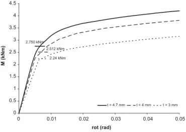
In order to verify the efficiency of this equation, numerical analyses are carried out and their results compared with those from the equation. The finite element model used is similar to the model described in Section 3. Various base plate thicknesses are considered, and the finite element results are compared with
the results obtained from Eq. 1. These results are shown inFig. 13, and good agreement between numerical and analytical results is observed for all thicknesses adopted.
This agreement between numerical and analytical results indicates the suitability of the proposed equation for prediction of the moment resistance for this base plate typology.
6. Conclusions
Drive-in racking systems are complex structures, due to interaction among their various components, which influences overall system behavior. This behavior is strongly dependent on connections and on the performance of other members.
In this work, the influence of base plate and portal beam– column connections in drive-in rack overall stability is analyzed. Base plate behavior is analyzed by a finite element model, and its momentrotation history is determined. Base plate behavior is linear in the initial branch, with a high-stiffness value. From a limit moment value, this stiffness declines progressively, and the behavior of the base plate changes.
Overall drive-in behavior is analyzed by comparing numerical and experimental results. From these analyses, it is observed that consideration of fully-fixed portal beam and base plate connec-tions leads to non-conservative results. Accordingly, this practice should be avoided in design procedures. It was also seen that consideration of a fully pinned base plate leads to entirely unsuitable values, and this assumption should always be avoided. Finally, it is observed that the outcomes for portal beam joints that are considered to be semi-rigid with semi-rigid or fully-fixed base plate connections leads to numerical results in good agreement with the experimental ones. This occurs due to the high base plate stiffness in the initial momentrotation history. Based on these results, for moment values lower than the limit moment at which the base plate stiffness declines, the described method can be used for design purposes with a fixed connection. An equation is presented that predicts the limit moment and that can therefore be employed in design procedures.
Acknowledgements
The authors acknowledge the support by CNPq (Conselho Nacional de Desenvolvimento Cientı´fico e Tecnolo´gico), CAPES (Coordenac-ao de Aperfeic~ -oamento de Pessoal de Nı´vel Superior) and FAPEMIG (Fundac-ao de Amparo~ a Pesquisa do Estado de Minas Gerais).
b d P
M
Fig. 12.Base plate parameters.
2.750 kNm 2.512 kNm
2.24 kNm
0 0.5 1 1.5 2 2.5 3 3.5 4 4.5
0
rot (rad)
M (kNm)
t = 4.7 mm t = 4 mm t = 3 mm
0.01 0.02 0.03 0.04 0.05
References
[1] Godley MHR, Beale RG, Feng X. Analysis and design of down-aisle pallet rack structures. Computers and Structures 2000;77(4):391–401.
[2] Baldassino N, Bernuzzi C. Analysis and behaviour of steel storage pallet racks. Thin-Walled Structures 2000;37(4):277–304.
[3] Sarawit AT, Pekoz T. Design of industrial storage racks. In: Proceedings of 16th international specialty conference on cold-formed steel structures, (Orlando, 17-18/10). 2002, p. 369–384.
[4] RMI. Specification for design, testing, and utilization of industrial steel storage racks. Charlotte, NC: Rack Manufacturers Institute; 1997.
[5] Godley MHR. The behaviour of drive-in storage structures. In: Proceedings of 16th international specialty conference on cold-formed steel structures, (Orlando, 17-18/10). 2002, p. 340–352.
[6] Freitas AMS, Freitas MSR, Campos SR. Comportamento de sistemas de armazenagem industrial do tipo drive-in. REM—Revista Escola de Minas
2003;56(4):237–42.
[7] Souza FT. Ana´lise Teo´rico-Experimental de Sistemas Aporticados com Elemen-tos Perfurados em Perfis Formados a Frio. M.Sc. thesis, UFOP, Ouro Preto, 2005. [8] Souza FT, Freitas AMS, Freitas MSR. Theoretical-experimental analysis of industrial storage racks drive-in. In: Proceedings of international colloquium on stability and ductility of steel structures. (SDSS Lisboa). 2006, p. 373–380. [9] ANSYS. User’s manual for revision 11. Houston, PA: Swanson Analysis
Systems Inc.; 2007.
[10] A´guia Industrial Storage Systems. Design of a drive-in storage system. 2004. [11] Oliveira AM. Ana´lise Teo´rico-Experimental de Sistemas Industriais de
Armazenagem (‘‘Racks’’). M.Sc. thesis, UFOP, Ouro Preto, 2000.
[12] Dı´az JJD, Nieto PJG, Biempica CB, Rougeot GF. Non-linear analysis of unbolted base plates by the FEM and experimental validation. Thin-Walled Structures 2006;44(5):529–41.
[13] Godley MHR. The behaviour of storage racking base plates. In: Proceedings of 6th international conference on steel and aluminium structures (ICSAS,07. Oxford). Oxford Brookes University; 2007. p. 433–440.