On the Nonlinear Transient Analysis of Planar Steel Frames
with Semi-Rigid Connections: From Fundamentals to
Algorithms and Numerical Studies
Abstract
This paper presents the fundamentals for prediction of a more realistic be-havior of planar steel frames with semi-rigid connections under dynamic loading. The majority of the research in this area concentrates on the non-linear static analysis of frames with semi-rigid connections. Indeed, few studies have contributed to the nonlinear dynamic and vibration analyses
of frames. Therefore, this article first describes the frames’ semi-rigid con-nection behavior under monotonic and cyclic loads, and presents the inde-pendent hardening technique adopted to simulate the joint behavior under cyclic excitation. In a finite element context, this paper presents an efficient numerical methodology that is proposed in algorithmic form to obtain the nonlinear transient response of the structural system. The paper also pre-sents, in algorithmic form, a complete description of the adopted connec-tion hysteretic model. Satisfying the equilibrium and compatibility
condi-tions, and assuming only the connection’s rotational deformation due to
bending as variable, this work obtains the tangent stiffness and mass ma-trices of the beam-column element with semi-rigid connections at the ends. The study concludes by verifying and validating the proposed numerical approach using four structural steel systems: a L-frame, a two-story frame, a six-story frame, and a four-bay five-story frame. The analyses show that the hysteresis of the semi-rigid connection has a strong effect on the
frames’ responses and is an important source of damping during the
struc-tural vibration.
Keywords
Steel frames, Nonlinear transient analysis, Geometric nonlinearities, Semi-rigid connections, Connection stiffness, Connection hysteretic behavior.
1 INTRODUCTION
In the structural design and construction of reticulated steel structures involving one or more floors, the beam-column and column-base connections play a significant role in their structural response. They also repre-sent a significant fraction of the total cost of the structure. Thus, the characteristics of these connections are, in steel structures, economically and structurally significant. Therefore, the engineer must have a good undering of the connection behavior. In most cases it is advisable to use semi-rigid connections. In fact, modern stand-ards (ABNT - NBR 8800, 2008; AISC, 2010; Eurocode 3, 2005) already include procedures to define the stiffness as well as strength of semi-rigid connections for computational analysis programs and prescriptions for the de-sign engineer.
Various studies on the static analysis of steel frames (King, 1994; Li et al., 1995; Kruger et al., 1995; Chen, 2000; Chan and Chui, 2000; Sekulovic and Nefovska-Danilovic, 2004; Cabrero and Bayo, 2005; Ihaddoudène et al., 2009; Valipour and Bradford, 2012) have already shown that the deformation and bending moment transmission capacity of the connections can significantly alter the load carrying capacity, the internal force distribution and global and local instability of these structures. In addition, within the civil, naval, oceanic, and aeronautical indus-tries, more resistant materials and new design and construction techniques have led to lighter and slender struc-tures, which are, however, usually susceptible to excessive vibration problems. Consequently, an essential part of
Andréa R. D. Silva a* Everton A. P. Batelo a Ricardo A. M. Silveira a Francisco A. Neves a Paulo B. Gonçalves b
a Departamento de Engenharia Civil, Escola de Minas, Universidade Federal de Ouro Preto, Minas Gerais, Brasil. E-mail: [email protected], [email protected], [email protected], [email protected]
b Departamento de Engenharia Civil, Pontifícia Universidade Católica do Rio de Janeiro, Rio de Janeiro, RJ, Brasil. E-mail: [email protected]
*Corresponding author
http://dx.doi.org/10.1590/1679-78254087
Received: June 05, 2017
a structural design should include an analysis of their dynamic behavior under various loading conditions. Re-search along these lines, accounting for the effect of connection flexibility, is still limited, particularly compared to the amount of research on static analysis. Numerical investigations into the behavior of steel structures with semi-rigid connections submitted to dynamic situations have been carried out by, among others, the following researchers: Valipour and Bradford (2012); Chan and Ho (1994); Lui and Lopes (1997); Xu and Zhang (2001); Sophianopoulos (2003); Silva et al. (2008); Galvão et al. (2010); Vimonsatit et al. (2012); Nguyen and Kim (2013) Attarnejad and Pirmoz (2014); and Aristizabal-Ochoa (2015).
Researchers have also experimentally evaluated the cyclic responses of semi-rigid connections. Bernuzzi et al. (1996), Calado (2003), and Shi et al. (2007) carried out tests using specific types of connections and proposed mathematical models to represent the observed behavior.
This article can be considered as an expansion of an earlier work by Galvão et al. (2010). In this context, the current paper evaluates, using the CS-ASA Program (Computational System for Advanced Structural Analysis; Silva, 2009), the nonlinear dynamic response of planar steel frame, considering geometric nonlinear effects and the semi-rigid characteristics of the connections between the structural elements. When the semi-rigid connec-tions are submitted to alternating repetitive acconnec-tions, they may develop an inelastic behavior that gives rise to hys-teretic damping, which is in most cases quite beneficial.
CS-ASA is a FEM-based computer system implemented in Fortran 90/95, originally designed for steel struc-tures. This program can perform advanced static and dynamic numerical analysis considering sources of nonline-arities such as second order effects and semi-rigid connections (using pseudo-springs at the finite element ends). Therefore, this paper brings the numerical results obtained from an alterated CS-ASA version, which allow repre-sent the semi-rigid connection hysteretic behavior, in order to allow a better modeling of the nonlinear transient response of planar steel frames with flexible joints. Actually, this is an extension of the CS-ASA initial module that contemplated the static nonlinear analysis and some cases for dynamic nonlinear analysis and vibration (Galvão
et al., 2010; Silva, 2009). As main contribution, in a finite element context, this paper presents an efficient numeri-cal methodology to obtain the nonlinear transient response of structural systems with semi-rigid joints. The pa-per also presents, in algorithm form, a complete description of the adopted connection hysteretic behavior.
The next section, Section 2, describes the connection behavior when subjected to monotonic and cyclical loads, and presents the adopted technique to simulate this behavior. Section 3 details the methodology used to obtain the nonlinear transient response of the structural system. Section 4 presents the formulation of the finite element used in the structural system’s modeling. Finally, to validate the proposed analysis methodology, Section 5 evaluates the dynamic response of four structural systems. The results demonstrate that the structural dynamic behavior can be greatly influenced by the effects of the semi-rigid connections and that a careful dynamic connec-tion descripconnec-tion and dynamic analysis is essential for a safe and yet cost-effective design.
2 SEMI-RIGID CONNECTIONS
As noted above, connections play a key role in the assembly, performance, and cost of a steel structure. In most cases, these connections cannot be modeled as perfectly rigid or ideally hinged. Rigid connections prevent any alteration of the angle between the interlinked elements, transferring the full moment from one extremity to the other. In the case of hinged connections, no moment is transmitted between the elements. These hypotheses simplify the analysis but fail to represent the true behavior of most structures. The experimental investigations of Jones et al. (1980; 1983) and Nethercot et al. (1998) demonstrated that a greater part of the connections used in current practices display semi-rigid behavior. This can substantially influence the overall stability of the structur-al system as well as the distribution of the forces acting on its elements. Indeed, geometric and mechanicstructur-al discon-tinuities can, according to Colson (1991), introduce localized effects and imperfections in the connections used in steel structures, which interfere with the overall behavior of the structure, providing justification for a more rig-orous investigation into these connection behavior. Such studies should take into account not only the manufac-turing and assembly point of view but also the connections’ influence on the structural response.
Not only the axial and shear forces but also the bending and torsion moments are transmitted through a con-nection. For a great majority of steel structures, however, the effects of these axial and shear forces on the defor-mation of the connection are small compared to those caused by the bending moment (Chen et al., 1996). For this reason, and knowing that in the analysis of planar structures the deformation caused by torsion is negligible, this study considers only the rotational deformation of the connection caused by bending.
experimental tests. Díaz et al. (2011) presented the main features of different connection models, highlighting the advantages and disadvantages of each one. Other studies have been performed to evaluate the behavior of con-nections under monotonic and cyclic loads, including (Ackroyd and Gerstle, 1982; Azizinamini et al., 1987; Yee and Melchers, 1986; Kishi and Chen, 1987a; Kishi and Chen, 1987b; Korol et al., 1990; Tsai and Popov, 1990; Abolmaali et al., 2003; Abolmaali et al., 2009). The following two subsections describe these behaviors as well as the numerical models adopted here.
2.1 Behavior under Monotonic Loading and Mathematical Representation
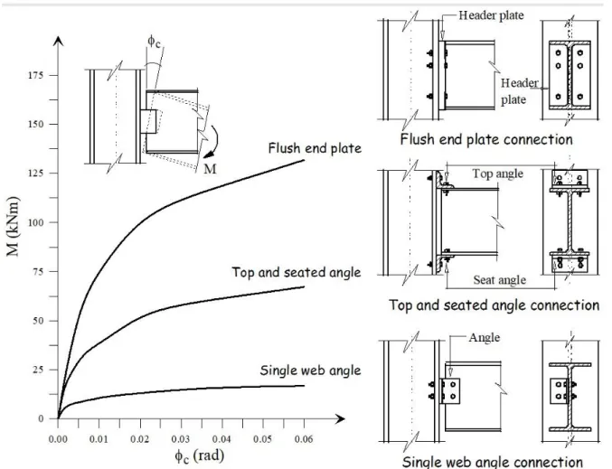
Figure 1 illustrates the typical behavior of three types of semi-rigid connections: the flush end plate, top and seat angle, and single web angle. In the figure the relative rotation between the interconnected elements, c, due to an applied moment is also shown. These connections, when submitted to bending, display a softening nonlinear behavior with decreasing stiffness. The moment-rotation curve is initially practically linear, but, as the load in-creases, the nonlinearity increases. This change in behavior is influenced by the existence of stress concentration, geometric imperfections and discontinuities and the plastic behavior of its components. At a certain loading level, these factors begin to interfere in the rotational capacity of the connection. In the final loading stage, the moment-rotation curve tends toward an asymptotical value known as the ultimate moment capacity of connection.
Figure 1: Moment-rotation curves of three usual types of connections under monotonic loading.
ele-ment’s length, where varies between 0 and 1. For a perfectly hinged connection 0and for an ideally rigid connection, 1, since Sc . The connection stiffness can be calculated by:
c c dM S
d (1)
where M is the bending moment acting on the connection and c is its rotational deformation. The moment-rotation curves can generally be written by one of the following expressions:
( ) ( ) c c
M f
g M (2)
which relate the moment to the rotation with mathematical expressions f and g, which usually depend on the geometry and disposition of the connecting components and the curve adjustment parameters.
According to Chan and Chui (2000), the mathematical models should provide a smooth moment-rotation curve with the first derivative positive and be able to represent various types of connections. For a linear connec-tion model only one parameter defining the joint stiffness is necessary. In this case, the moment-rotaconnec-tion relaconnec-tion- relation-ship is given by:
cini c
M S (3)
where Scini represents the initial stiffness. This is the simplest model and has been widely used in the analysis of semi-rigid connections (Arbabi, 1982; Kawashima and Fujimoto, 1984; Chan, 1994; Lui and Chen, 1986). For large displacement analyses, however, it may lead to erroneous conclusions.
Unlike the linear model, the nonlinear models simulate the stiffness degradation as the load increases. Among the various nonlinear models found in literature, only those employed in this study are discussed.
The first is an exponential model (Lui and Chen, 1986; Chen and Lui, 1991), whose mathematical expression for the moment-rotation curve is given by:
0 1 1 exp 2 n c
j p c
m
M M C R
m (4)
where M is the moment in the connection, M0 is the initial moment, Rp is the strain-hardening stiffness of the
connection, is an scaling factor, and Cm—m 1,2,...n — is the curve-fitting coefficient.
Also used here is a four-parameter model proposed by Richard and Abbott (1975). The model describes the connection behavior according to the relationship:
1
0
+
1 /
cini p c
p c
n n
cini p c
S R
M R
S R M
(5)
in which Rp is the strain-hardening stiffness when ctends to infinity; n is a parameter that defines the
sharpness of the curve, and M0 is a reference moment. A study made by Kishi et al. (2004) demonstrated that this model is effective in establishing the behavior of an end plate connection. However, it can be applied to any type of connection. To do this, it is sufficient to either experimentally or numerically evaluate the four necessary parameters. From this model, three others can be obtained: linear (Rp Scini), bilinear (n ), and ignoring
2.2 Behavior under Cyclic Loading and Mathematical Representation
When a realistic numerical simulation of a given structural system under dynamic loads is desired, it is es-sential to consider the behavior of the connection under cyclic load. Depending on the load level and time history, semi-rigid connections may develop an inelastic behavior. A typical connection response is illustrated in Fig. 2.
Figure 2: Connection behavior under cyclic loading.
In Figure 2 the 0Acurve describes the connection’s behavior during the initial loading process of the
struc-ture, which is compatible with the different types of connection shown in Fig. 1. The following AB and BC paths correspond to the unloading process characterized by a decreasing intensity of the bending moment that acts on the connection and the reversal of the direction of the external forcing, as shown by the arrows. The subsequent
CD and DE paths correspond to the next unloading and loading cycles. After the first unloading stage is complete, only a part of the total deformation cais recovered and the connection sustains a permanent residual
defor-mation cb. This also occurs after each of the following loading and unloading cycles. The loops resulting from the non-coincident moment-rotation curves characterize the connection hysteretic behavior, as shown, through cyclic loading tests, by Tsai and Popov (1990), Korol et al. (1990) and Abolmaali et al. (2003).
The nonlinear behavior of the semi-rigid connections when submitted to cyclic loads can be efficiently simu-lated by the independent hardening technique, employed previously by, among others, Ackroyd and Gerstle (1982), Azizinamini et al. (1987), Chen et al. (1996), Chan and Chui (2000) and Sekulovic and Nefovska-Danilovic (2008). An important advantage of this approach is that one can adopt any mathematical function representing the moment-rotation relationship under monotonic loads.
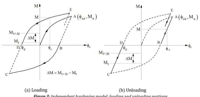
Consider a typical trajectory under increasing load (trajectories indicated by the continuous lines in Fig. 3a) beginning at a point with coordinate p, the last permanent residual rotation (at 0A, the initial loading phase,
0
p ), the bending moment M at any position along the trajectory DE can be calculated as follows:
( c p)
M f (6)
( )
c c p
c c dM S
d (7)
The loading process between a time step t (prior) and t t (actual) leads to an increase in the bending moment, M, which has the same sign of the bending moment, M. Therefore, the loading condition is verified if
0
M M .
In the unloading process, based on experimental results, a linear moment-rotation relation with an inclina-tion equal to the initial stiffness of the connecinclina-tion is considered, as illustrated by the solid lines in Figure 3b. Con-sider, for example, the segment AB of the hysteretic cycle. The straight line starting at point A( ;c Ma) (the end of
the preceding loading cycle) with an inclination Scini is defined as:
( )
a cini ca c
M M S (8)
where Ma is the reverse moment at which unloading starts, which can be obtained from Eq. (6) considering
c ca.
During the unloading process, the relation M M 0is obeyed. In some case, however, additional clarifi-cations are necessary. Consider again Fig. 2. If the connection is being unloaded from A to B and the loading pro-cess begins before the unloading has been completed, say at F, the moment-rotation behavior of this element will follow the FA trajectory until it reaches the last reverse moment encountered. At this point, the loading process follows the original moment-rotation curve obtained, considering the last permanent rotation p.
Figure 3: Independent hardening model: loading and unloading portions.
In computing the independent hardening model, the rotation p should be stored after each complete
un-loading cycle. The reverse moment,Ma, should also be stored every time Mchanges sign. In addition, the inter-vals between the two successive time instants should be small so that these variables can be defined with ade-quate precision.
3 METHODOLOGY FOR NONLINEAR DYNAMIC ANALYSIS
The equations of motion that governs the dynamic response of a structural system can be obtained using the virtual work principle or the virtual displacement principle. Considering the internal, inertial and dissipative forc-es, the equilibrium at time t t, can be expressed as (Zienkiewicz and Taylor, 1991):
t t t
T
ij ij k k k k k ek
V V V
where ij represents the Cauchy tensor in equilibrium with external excitation fek; ijrepresents the virtual
Green-Lagrange deformation components corresponding to arbitrary displacements dk, which are cinematically compatible with the boundary conditions; is the mass density of the material and is the viscous damping coefficient. To determine the equilibrium configuration of the structure at t t, the updated Lagrangian referential is used. In this case, the configuration at instant t is used as the reference for analysis.
The advantage of using the updated Lagrangian referential depends on the finite element formulation adopt-ed (Bathe, 1996). Wong and Tin-Loi (1990) and Alves (1993) showadopt-ed that the results obtainadopt-ed using the initial Lagrangian referential leads to accumulated errors if linear interpolation functions (Silveira, 1995) are adopted in the FE formulation due to possible rigid body motions during the incremental process. With an updated Lagrangi-an referential, these simplified interpolation functions cLagrangi-an be applied, as the referential is updated at every in-crement and rigid body rotations are divided into smaller parts.
According to the usual finite element procedures, and using Eq. (9), the following matrix equation in terms of the nodal displacements is obtained:
( ) ( )
i t r
MU CU F U F (10)
where M and C are the mass and damping matrices, respectively; i
F is the internal force vector; U,Uand U,
represent the displacement, velocity and acceleration vectors, of the structural system, respectively; Fr is the
vector that defines the external excitation; and is the load intensity at a instant t.
The stiffness matrix is a function of three variables—the nodal displacements, the internal forces of each el-ement, and connection stiffness and must be continuously updated using an incremental-iterative solver strategy to capture the second-order effects (P andP ) and connection behavior. To this end, a numerical proce-dure that combines the Newmark (Chopra, 1995) and Newton-Raphson (Burden and Faires, 2004) methods is adopted. The necessary computational steps are detailed in Appendix A. Notice that the connection stiffness is updated at the end of each iterative cycle. Appendix B summarizes, in algorithmic form, the connection hysteretic model implemented here and described in Section 2.
4 THE SEMI-RIGID FINITE ELEMENT
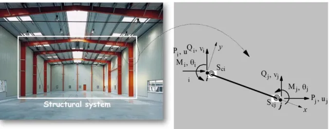
In most structural analysis programs springs are used to model the connections. Figure 4 shows the planar beam-column element, with nodal points i and j, and two springs fixed at the extremities. They permit the connec-tions’ degree of freedom to be incorporated into the tangent stiffness of the beam-column element. Only the con-nection’s rotational deformation due to bending is considered.
Figure 4: Beam-column element with semi-rigid connections.
Figure 5 shows a deformed configuration of the finite element, the internal forces and deformations in the springs, where Sci and Scjdenote the stiffness of the spring elements. The connections can be characterized by
be-tween the rotational angles of the side connected with the global node of the element, c, and the one connected
to the beam-column element, b. Using Eq. (6) and the moment equilibrium of the spring elements, the following relations are obtained:
θ θ
ci ci ci ci
bi ci ci bi
M S S
M S S (11)
θ θ
cj cj cj cj
bj cj cj bj
M S S
M S S (12)
where Mc and Mb are the bending moments acting on the spring elements and on the beam-column element, respectively, and the subscripts i and jrefer to the element’s extremities.
The effect induced by connection flexibility is accounted for by modifying the element stiffness matrix. Here-in, the spring elements simulating the connection’s flexibility have null lengths and the moment-rotation equilib-rium relation is given by:
(3,3) (3,6)
(3,3) (3,3)
4 2 4 2 2
15 30
2 2 4 2 4
30 15
bi bi bi
bj bj bj
EI PL PL EI PL PI
M k k L AL L AL
k k
M EI PL PI EI PL PL
L AL L AL
(13)
where E is the Young’s modulus; I and A are, respectively, the element cross section inertia and area; L is the element’s length; and P is the axial force. The terms of the matrix are the coefficients of a conventional beam-column element stiffness matrix with perfectly rigid connections, determined using the nonlinear geometrical formulation proposed by Yang and Kuo (1994), assuming large displacements and rotations, but small deformations.
Combining Eqs. (11)-(13), results in:
θ θ θ θ (3,3) (3,6) (6,3) (6,6) 0 0 0 0 0 0 ci ci ci ci ci ci bi bi cj cj bj bj
cj cj cj cj
S S
M
S S k k
M
k S k S
M
M S S
(14)
Assuming that the loads are only applied at the global nodes of the element (see Fig. 5), the internal moments
bi
M and Mbj are equal to zero, and the following moment-rotation equilibrium relations is obtained:
θ θ
(6,6) (3,6)
(6,3) (3,3)
0 1 0 0
0 0 0
cj
ci ci ci ci ci
cj cj cj ci cj cj
S k k
M S S S
M S S k S k S (15)
in which Sci k(3,3) Scj k(6,6) k(6,3) (3,6)k .
Figures 4 and 5 show that Mi Mciand Mj Mcj. Thus, the relationship between the shearing forces and
the bending moments, obtained by the equilibrium force and moment, can be written in an incremental matrix form as follows:
1 / 1 /
1 0
1 / 1 /
0 1 i ci i cj j j L L Q M M
L L M
Q M
(16)
with Miand Mjbeing the incremental nodal moments, Qiand Qjbeing the incremental shearing forces
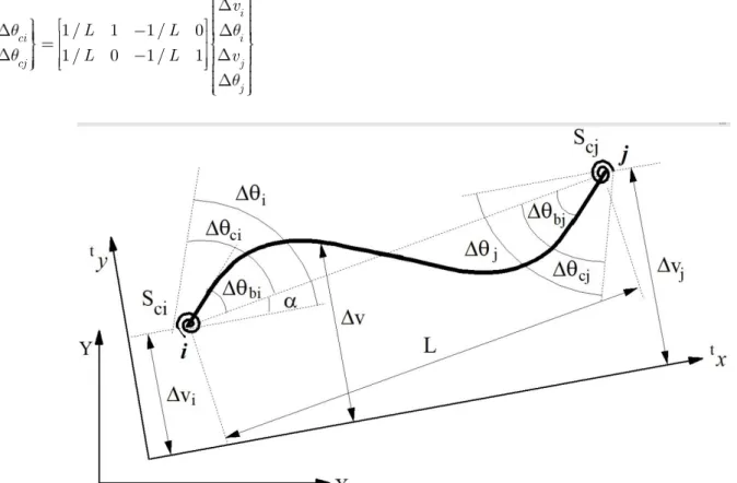
Figure 5: Deformed configuration and spring element degree of freedom.
Observing Fig. 6, it is possible to establish the relations:
1 / 1 1 / 0
1 / 0 1 / 1
i
ci i
cj j
j v
L L
L L v (17)
Figure 6: Nodal displacements of the semi-rigid beam-column element.
By substituting (15) into (16), using (17), and performing all the necessary operations, the semi-rigid ele-ment stiffness matrix is then obtained considering both the connection flexibility and the geometric nonlinear effects. Using these new terms in the complete 6x6 order matrix of the conventional beam-column element, the element stiffness matrix is finally obtained in the local coordinates system. In this formulation, the relation be-tween the axial forces Pi and Pj, and the nodal displacements suffer no alterations when considering the
4.1 Semi-Rigid Finite Element Mass Matrix
The consistent mass matrix for the beam-column element is defined as (Kishi and Chen, 1986):
T e
tV
dV
M H H (18)
where H is the interpolation functions matrix.
According to Chan and Chui (2000), the transversal displacement v of the beam element can be written, in an incremental form, using the following matrix expression:
2 2
1 2 2 1 1 1 2 2
( ) bi 3 2 3 2 i
bj j
v
v x H H L H H L H H H H
v (19)
where viand vjare the incremental vertical displacements of the nodes i and j, and biand bjare the
rotations of these same nodes, as shown in Fig. 6. In addition, H1 1 x/LandH2 x/L.
To introduce the connection’s flexibility effect into the previous expression and thereby obtain the desired mass matrix, the beam-column nodal rotations are related to the rotations at the ends of the element with semi-rigid connections as:
1
4 2
0
2 4 0
ci
bi ci ci
bj cj cj
cj
EI EI
S S
L L
EI EI S
S
L L
(20)
Substituting Eq. (17) into Eq. (20) and using Eq. (19), the function that describes the transversal displace-ment field of a beam with semi-rigid connections is obtained, i.e.:
*
( ) i i j j T
v x H v v (21)
in which,
1
2 2
1 2 2 1
1 1 2 2
4 2
0 1 / 1 1 / 0
( )
2 4 0 1 / 0 1 / 1
3 2 0 3 2 0
ci ci
cj cj
EI EI
S S L L
L L
v x H H L H H L
EI EI S L L
S
L L
H H H H
(22)
The mass matrix components influenced by the connection’s stiffness are obtained using the H* matrix, in-stead of the H in Eq. (18). The other terms are identical to those developed for the conventional beam-column element with rigid connections (Silva, 2009).
5 NUMERICAL APPLICATIONS
In this section, we use the proposed methodology to obtain the nonlinear dynamic response of four planar structural steel systems: a L-frame, a two-story frame, a six-story frame, and a four-bay five-story frame. In these examples, viscous damping is not considered when the dissipative effect of the connection nonlinear hysteretic behavior on the dynamic response is evaluated.
5.1 L-Frame
connec-tion. In addition to these authors, Shi and Atluri (1989) and Chan and Chui (2000) used this structure to test their numerical formulations for dynamic analyses of plane frames applying an impact load (19.6 N) in the middle of the frame column. The application of a load with low value is justified by the low resistance of the semi-rigid con-nection of the beam-column elements. Table 1 compares the present results with the natural frequencies corre-sponding to the first two vibration modes obtained by the aforementioned authors. The results agree well with those found in literature.
Figure 7: L-shaped frame: geometry and loading.
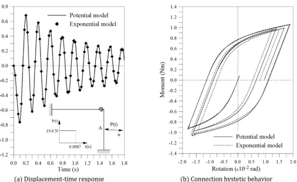
To evaluate the influence of the connection’s nonlinear behavior on the dynamic response, a short-duration impact load P(t) with a constant intensity of 19.6 N is applied at the center of the column, as shown in Fig. 7. To verify the importance of the adopted semi-rigid connection’s moment-rotation function in this representation, two models are considered: the exponential [59] and the four-parameter model (Chen and Lui, 1991). The pa-rameters for the exponential model, described by Eq. (4), are as follows: m=6, C1 = 1.078915, C2 = 18.148410, C3 = 52.890917, C4 = -34.035435, C5 = -37.194613, C6 = 43.896458, α = 0.000384, Rp = 95.55031 kgfcm/rad and Mo = 0. For the four-parameter model (Eq. 5), in addition to the previous initial stiffness, the following values are used: Rp = 8.826 Nm/rad, Mo = 0.883 Nm and n = 1.7.
Table 1: The two lowest natural frequencies of the L-frame (rad/s).
Types of Connections
Present work
Kawashima and Fujimoto
(1984) Shi and
At-luri (1989)
Chan and Chui (2000) Numerical
Experi-mental
Rigid ω1 = 15.81 ω1 = 16.30 ω1 = 15.50 ω1 = 15.87 −
ω2 = 34.74 ω2 = 35.90 ω2 = 30.80 ω2 = 35.30 − Semi-rigid ω1 = 14.90 ω1 = 14.90 − ω1 = 14.75 ω1 = 15.22
ω2 = 32.77 ω2 = 33.00 − ω2 = 32.06 ω2 = 33.52
Figure 8: L-shaped frame: geometry and loading.
The comparison between the connection’s linear and nonlinear responses is shown in Fig. 9. The vibration period is practically the same in both cases, since the same initial stiffness of the connection is considered. How-ever, the nonlinearity of the connection leads to a strong decrease in the vibration amplitude, due to energy dissi-pation during each hysteretic cycle, as illustrated in Fig. 9b, where the connection’s moment-rotation response is displayed.
Figure 9: Dynamic behavior of the L-frame with semi-rigid connection.
Figure 10: Different connection models used in the L-frame analysis.
5.2 Two-Story Frame
The next structure to be investigated is the single-bay, two-story frame subjected to horizontal loads applied at the top of each pavement, as illustrated in Fig. 11. For the beams, a W360x72 profile is adopted, and for the columns, a W310x143 profile. Young’s modulus is equal to 205 GPa. Two concentrated masses of 3730 kg are considered at the extremities of each beam and in the middle, a mass of 7460 kg. The structure is then analyzed considering a periodic load and a rectangular pulse, (see Fig. 11).
Figure 11: Single-bay, two-story portal frame: geometry and loads.
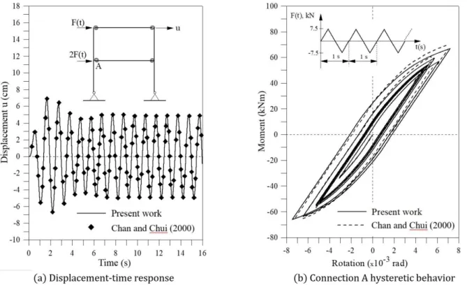
Figure 12a illustrates the time response obtained for the horizontal displacement at the top of the structure when submitted to a periodic load, where the present results are compared with those by Chan and Chui (2000). In the transient regime the displacement reaches a maximum of around ±7 cm. After approximately 6s, the struc-ture reaches the permanent regime with an amplitude of ±5 cm, when the energy introduced into the strucstruc-ture by the external loads and the energy dissipated through the semi-rigid connections are balanced. The connec-tion’s moment-rotation behavior during the total response is shown in Fig. 12b.
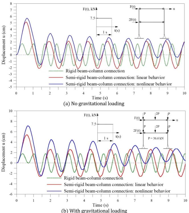
To investigate the effect of gravitational loads and the P- δ effect on the nonlinear dynamic response, gravita-tional static loads of 36.6 kN at the extremities and of 73.2 kN in the middle of the beam are considered. These loads induces an increase of the axial forces in the columns and additional bending moments, reducing the stiff-ness of these members and, consequently, of the structural system. The analysis is performed considering a rec-tangular pulse of 7.5 kN acting during 1s. Three types of beam-column connections are considered: rigid, linear semi-rigid and nonlinear semi-rigid. Figures 13a-b exhibits the time history of the horizontal displacement at the top of the structure respectively with and without the presence of the gravitational forces. In both cases the semi-rigid connection leads to a strong increase in the displacements and, consequently on the stresses and strains. The maximum displacement for the nonlinear semi-rigid connection is more than three times than that of the frame with rigid connections. This underlines the importance of a detailed dynamic analysis of portal frames with semi-rigid connections and explains the usually large vibration amplitudes of these structures.
Figure 12: Transient response of the single-bay, two-story portal frame under periodic load.
Figure 13: Transient response of the single-bay, two-story portal frame under a rectangular pulse.
5.3 The Six-Story Vogel Frame
Figure 14: Two-bay, six-story Vogel frame: geometry and loading.
connections, when submitted to the action of the load whose frequency is equal to the natural frequency, it would show a resonant response (with vibration amplitudes increasing linearly). This was also expected for the frame with semi-rigid connections, however, when the frame is analyzed with semi-rigid connections with non-linear behavior, its amplitude of vibration also increases, but this is limited by the hysteretic damping which, as shown here, has a beneficial effect in the resonance region. For ωc = 2.41 rad/s, the frame with rigid connections display a resonant response, as illustrated in Fig. 15c. For ωc = 3.33 rad/s, Fig. 15d, outside the main resonance region, a sharp decrease in the vibration amplitudes are observed in all cases. Shown in Figs. 16a-b are the moment-rotation hysteretic cycles for the beam-column connection identified inset Fig. 16b considering ωc = 1.66 rad/s and ωc = 2.41 rad/s, respectively. Comparing the hysteretic cycles, it is observed that the amount of energy dissi-pated when ωc= 1.66 rad/s is greater than that for ωc = 2.41 rad/s, which is in agreement with the time respons-es in Figs. 15b-c, highlighting the influence of the nonlinear moment-rotation behavior of the semi-rigid connec-tions on the dynamics of steel structures.
Figure 16: Connection hysteretic behavior.
5.4 Four-Bay Five-Story Frame
This last example investigates a four-bay, five-story steel frame located in Shanghai, China, under seismic ex-citation. The results show how semi-rigid connections can significantly alter the dynamics of steel structures un-der base excitation to ensure adequate strength and prevent collapse. Its geometric configuration is shown in Fig. 17a. The flush end plate beam-column connections are adopted and their behavior is represented by the Richard-Abbott model with the parameters: Scini = 12336,86 kNm/rad, Rp = 112,97 kNm/rad, M0= 96,03 kNm and n = 1,6 (Nguyen, 2010). Gravitational loads are also included as additional lumped masses at the beams’ nodes. The effect of a mesh refinement in the beams is also considered. The frame is assumed to be subjected to the first ten sec-onds of the 1940 El Centro N-S earthquake component, shown in Fig. 17b, with a peak ground acceleration of 0.31g.
First, the free vibration analysis on the structure, considering the beam-column rigid connections, is per-formed. The results are presented in Table 2 for the first two natural periods of vibration. Table 3 presents the results considering semi-rigid connections. In both cases an excellent agreement with the results by Nguyen (2010) is observed. Also, the influence of the beam discretization is negligible. Figure 18 shows the variation of the first five natural frequencies of the frame, parametrized by the respective value considering a rigid connec-tion, as a function of the beam-column connections flexibility, γ. All natural frequency ratios increase with γ and converges to one at γ = 1. The connection flexibility has a significant influence on the variation of the natural fre-quencies, particularly on the lowest frequencies. As the natural frequencies decrease increases the influence of environmental loads, whose spectral content is located usually in the low frequencies range. This fact can be very important for frames under seismic loads, as the lower modes may have strong influence on a building’s seismic response.
Figure 17: Transient response of the single-bay, two-story portal frame under a rectangular pulse.
Table 2: First two natural periods of vibration (s) for the frame with rigid connections.
Modes Nguyen (2010)
Present Work One
ele-ment
Two ele-ments
Five ele-ments
1 1.2282 1.1818 1.1820 1.1824
The first- and second-order elastic transient responses of the building with rigid connections are presented in Fig. 20a and compared with the nonlinear second order response obtained by Nguyen (2010).
Table 3: First two natural periods of vibration (s) for the frame with flexible connections.
Modes Nguyen (2010)
Present Work One
ele-ment
Two ele-ments
Five ele-ments
1 2.700 2.623 2.623 2.623
2 0.777 0.733 0.773 0.770
Figure 18: Influence of beam-column connection flexibility on natural frequencies.
Figure 19: Beam-column connection hysteretic behavior.
hysteretic behavior (Richard Abbott model) and an increasing number of finite elements in the beams’ discretiza-tion process. Again, a good agreement with the results found in (Nguyen, 2010) is observed. Comparing the re-sults, the marked influence of the structure’s geometric nonlinearity on the dynamic response is observed. The consideration of the connections’ flexibility significantly amplifies the displacements (compare Figure 20a and Figure 20b).
The connections nonlinearity, Figure 20b, decreases the displacements in comparison with the linear case, but the results are higher than those with rigid connections. The second-order effects lead to a slight increase in the vibration amplitudes. Finally, the beams discretization has no detectable effect on the results.
6 FINAL REMARKS
This article presents the fundamentals for prediction of a more realistic behavior of frames with semi-rigid connections under dynamic loading. In the structural behavior evaluation, the effects of geometric nonlinearity and connection flexibility are considered. Different types of connections are considered and compared. Numerical studies are carried out for four structures with different geometries and load conditions. The obtained results are compared with experiments and solutions available in the literature. The coincidence or not with the results of others authors can be strongly influenced by the geometric nonlinear finite element formulation adopted, since the structures studied are slender. But Good agreement is found in all cases, confirming the efficiency of the for-mulation and numerical solution strategy adopted herein. Thus the numerical approach proposed here can be efficiently used to evaluate the nonlinear transient response of planar steel structures with semi-rigid connec-tions.
The connections flexibility may decrease significantly the natural frequencies, increasing consequently the effect of environmental loads such as wind and earthquakes on the dynamic response of the structure. Thus, these loads may induce resonance and therefore large amplitude oscillations beyond the acceptable maximum values, which dramatically reduce the comfort (sea-sickness) and therefore limit the use of the building, may cause low cycle fatigue or even impair the safety of the structure, producing unacceptable economic losses. For example, the ASCE Standard (ASCE 7-05, 2006) classifies a structure as dynamically sensitive, or “flexible”, if the lowest natural frequency < 1 Hz. When considering the hysteretic behavior of the connection, a gradual reduction of the dis-placement amplitudes is observed. The damping introduced by the connection’s nonlinear hysteretic behavior decreases the vibration amplitudes, increasing the safety of the structure. This damping is measured by the con-nection’s capacity to dissipate energy in each cycle, which can be evaluated by calculating the enclosed area of the curve that relates the force acting on the connection to its deformation. Viscous damping was not considered in the present analysis to draw attention to the influence of the connection’s dissipative properties. Although benefi-cial, viscous damping coefficients of slender steel frames are usually very low. The connection behavior is shown to have a strong influence on the results. As the spring model is used to represent the semi-rigid joint behavior, the number of springs depends on the number of structure connections. Thus the consideration of the true con-nection behavior is extremely important for a realistic forecasting of the dynamic response and resistance of a structural steel frames. Finally, second order effects are shown to increase the vibration amplitudes, reducing the comfort and safety of tall building frames.
Acknowledgments
The authors wish to express their gratitude to CAPES and CNPq, FAPEMIG and UFOP for the support received in the development of this research. Special thanks go to Prof. Harriet Reis and Prof. John White for their editorial reviews.
References
ABNT - NBR 8800. (2008). Project and Execution of Steel Buildings Structures, Brazilian Association of Technical Standards, Rio de Janeiro, Brazil (in Portuguese)
Abolmaali, A., Kukreti, A., Motahari, A., Ghassemieh, M. (2009). Energy dissipation characteristics of semi-rigid connections. Journal of Constructional Steel Research 65: 143-171.
Abolmaali, A., Kukreti, A.R., Razavi, H. (2003). Hysteresis behavior of semi-rigid double web angle steel connec-tions. Journal of Constructional Steel Research 59: 1057-1082.
AISC. (2010). Specification for Structural Steel Buildings, American Institute of Steel Construction, ANSI/AISC 360-05, Chicago, IL.
Alves, R. V. (1993). Formulation forgeometric nonlinear analysis in Total Lagrangian reference. 1º Doctoral Semi-nar (in Portuguese), COPPE/UFRJ, Rio de Janeiro/RJ, Brazil.
Arbabi, F. (1982). Drift of flexibly connected frames. Computers & Structures, 15(2): 102-108.
Aristizabal-Ochoa, J. D. (2015). Stability of imperfect columns with nonlinear connections under eccentric axial loads including shear effects. International Journal of Mechanical Sciences 90: 61 76.
ASCE 7-05. (2006). Minimum Design Loads for Buildings and Other Structures, American Society of Civil Engi-neers, Reston, Virginia.
Attarnejad, R. and Pirmoz, A. (2014). Nonlinear analysis of damped semi-rigid frames considering moment-shear interaction of connections. International Journal of Mechanical Sciences 81: 165 173.
Azizinamini, A., Bradburn, J.H., Radziminski, J.B. (1987). Initial stiffness of semi-rigid steel beam-to-column joints. Journal of Constructional Steel Research 8: 71-90.
Bathe, K.J. (1996). Finite Element Procedures. Prentice-Hall, New Jersey.
Bernuzzi, C., Zandonini, R., Zanon, P. (1996). Experimental analysis and modelling of semi-rigid steel joints under cyclic reversal loading.Journal of Constructional Steel Research 38(2): 95 123.
Bjorhovde, R., Colson, A., Brozzetti, J. (1990). Classification system for beam-to-column connections. Journal of Structural Engineering 116(11): 3059-3077.
Burden, R.L. and Faires, J.D. (2004). Numerical Analysis, 8th edition, Brooks Cole.
Cabrero, J.M. and Bayo, E. (2005). Development of practical design methods for steel structures with semi-rigid connections. Engineering Structures 27: 1125 1137.
Calado, L. (2003). Non-linear cyclic model of top and seat with web angle for steel beam-to-column connections. Engineering Structures 25: 1189–1197.
Chan, S.L. (1994). Vibration and modal analysis of steel frames with semi-rigid connections. Engineering Struc-tures 16(1): 25-31.
Chan, S.L. and Chui, P.P.T. (2000). Non-linear Static and Cyclic Analysis of Steel Frames with Semi-Rigid Connec-tions. Elsevier, Oxford.
Chan, S.L. and Ho, G.W.M. (1994). Nonlinear vibration analysis of steel frames with semi-rigid connections. Journal of Structural Engineering 120(4): 1075 1087.
Chen, W.F. (2000). Practical Analysis for Semi-rigid Frame Design. Singapore: World Scientific.
Chen, W.F., and Lui, E.M. (1991). Stability Design of Steel Frames. CRC Press, Boca Raton, Florida.
Chen, W.F., Goto, Y., Liew, L.Y.R. (1996). Stability Design of Semi-rigid Frames. John Wiley & Sons Inc., USA.
Colson, A. (1991). Theoretical modeling of semi-rigid connections behavior. Journal of Constructional Steel Re-search 19: 213-224.
Cunningham R. (1990). Some aspects of semi-rigid connections in structural steelwork. The Structural Engineer 68(5): 85-92.
Díaz, C., Martí, P., Victoria, M., Querin, O.M. (2011). Review on the modelling of joint behaviour in steel frames. Journal of Constructional Steel Research 67: 741-758.
Eurocode 3. (2005). Design of Steel Structures. Part 1.8: Design of Joints. European Committee for Standardization (CEN) Brussels, Belgium.
Galvão, A.S., Silva, A.R.D., Silveira, R.A.M., Gonçalves, P.B. (2010). Nonlinear dynamic and instability of slender frames with semi-rigid connection. International Journal of Mechanical Sciences 52: 1547 1562.
Ihaddoudène, A.N.T., Saidani, M., Chemrouk, K. (2009). Mechanical model for the analysis of steel frames with semi-rigid joints. Journal of Constructional Steel Research 65: 631-640.
Jones, S.W., Kirby, P.A., Nethercot, D.A. (1980). Effect of semi-rigid connections on steel column strength. Journal of Constructional Steel Research 1: 38 46.
Jones, S.W., Kirby, P.A., Nethercot, D.A. (1983). The analysis of frames with semi-rigid connections – a state-of-the-art report. Journal Construction Steel Research 3(2): 2-13.
Kawashima, S., Fujimoto, T. (1984). Vibration analysis of frames with semi-rigid connections. Computers & Struc-tures 19: 85 92.
King, W.S. (1994) The limit loads of steel semi-rigid frames analyzed with different methods. Computers & Struc-tures 51(5): 475-487.
Kishi, N. and Chen, W.F. (1987a). Moment-rotation Relation of Top and Seat Angle Connections. Structural Engi-neering Report No. CE-STR-87-4, School of Civil EngiEngi-neering, Purdue Univ., West Lafayette.
Kishi, N. and Chen, W.F. (1987b). Moment-rotation Relation of Semi-rigid Connections. Structural Engineering Report No. CE-STR-87-29, School of Civil Engineering, Purdue Univ., West Lafayette.
Kishi, N., and Chen, W.F., (1986). Data Base of Steel Beam-to-column Connections. Structural Engineering Report No. CE-STR-93-15, School of Civil Engineering, Purdue Univ., West Lafayette, IN.
Kishi, N., Komuro, M., Chen, W.F. (2004). Four-parameter power model for M–θ curves of end-plate connections. In: ECCS/AISC workshop connections in steel structures V: Innovative steel connections.
Korol, R.M., Ghobarah, A., Osman, A. (1990). Extended end-plate connections under cyclic loading: behavior and design. Journal of Constructional Steel Research 16: 253-280.
Kruger, T.S., Rensburg, B.W.J., Plessis, G.M. (1995). Nonlinear analysis of structural steel frames. Journal of Con-structional Steel Research 34: 285-306.
Li, T.Q., Choo, B.S., Nethercot, D.A. (1995). Connection element method for the analysis of semi-rigid frames. Jour-nal of ConstructioJour-nal Steel Research, 32: 143 171.
Lui, E.M. and Lopes, A. (1997). Dynamic analysis and response of semirigid frames. Engineering Structures, 19(8): 644 654.
Nethercot, D.A., Li, T.Q., Ahmad, B. (1998). Unified classification system for beam-to-column connections. Journal of Constructional Steel Research 45(1): 39-65.
Nguyen, P-C. (2010). Nonlinear Analysis of Planar Semi-Rigid Steel Frames subjected to Earthquakes using Plastic Zone Method. Master Dissertation (in Vietnamese). Hồ Chí Minh, Vietnam.
Nguyen, P-C. and Kim, S-E. (2013). Nonlinear elastic dynamic of space steel frames with semi-rigid connections. International Journal Constructional Steel Research84: 72 81.
Richard, R.M. and Abbott, B.J. (1975). Versatile elastic-plastic stress-strain formula.Journal of the Engineering Mechanics Division 101(4): 511-515.
Sekulovic, M. and Nefovska-Danilovic, M. (2004). Static inelastic analysis of steel frames with flexible connections. Journal of Theoretical and Applied Mechanics 31(2): 101-134.
Sekulovic, M., and Nefovska-Danilovic, M. (2008). Contribution to transient analysis of inelastic steel frames with semi-rigid connections, Engineering Structures 30: 976–989.
Shi, G. and Atluri, S.N. (1989). Static and dynamic analysis of space frames with nonlinear flexible connections. International Journal for Numerical Methods in Engineering 28: 2635-2650.
Shi, G., Shi, Y., Wang, Y. (2007). Behavior of end-plate moment connection under earthquake loading. Engineering Structures, 29: 703-716.
Silva, A.R.D. (2009). Computational System for Static and Dynamic Advanced Analysis of Steel Frames. D.Sc. Dis-sertation, Graduate Program in Civil Engineering, Federal University of Ouro Preto (UFOP), Ouro Preto/MG, Bra-zil. (in Portuguese).
Silva, J.G.S., Lima, L.R.O., Vellasco, P.C.G.S., Andrade, S.A.L., Castro, R.A., (2008). Nonlinear dynamic analysis of steel portal frames with semi-rigid connections. Engineering Structures 30: 2566–2579.
Silveira, R.A.M. (1995). Analysis of structural elements slender with unilateral Contact Constraints. Ph.D. Thesis (in Portuguese). Graduate Program in Civil Engineering, PUC-Rio, Rio de Janeiro/RJ, Brazil.
Sophianopoulos, D.S. (2003). The effect of joint flexibility on the free elastic vibration characteristics of steel plane frames. Journal of Constructional Steel Research 59: 995–1008.
Tsai, K.C. Popov, E.P. (1990). Cyclic behavior of end-plate moment connections. Journal of Structural Engineering 116(11): 2917-2930.
Valipour, H.R. and Bradford, M. (2012). An efficient compound-element for potential progressive collapse analysis of steel frames with semi-rigid connections. Finite Elements in Analysis and Design, 60: 35-48.
Vimonsatit, V., Tangaramvong, S., Tin-Loi, F. (2012). Second order elastoplastic analysis of semirigid steel frames under cyclic loading. Engineering Structures 65: 1187-1197.
Vogel, U. (1985). Calibrating Frames, Stahlbau 54: 295-311.
Xu, Y.L. and Zhang, W.S. (2001). Modal analysis and seismic response of steel frames with connection dampers. Engineering Structures 23 385–396.
Yang, Y.B. and Kuo, S.B. (1994). Theory & Analysis of Nonlinear Framed Structures. Prentice Hall.
Yee, Y.L. and Melchers, R.E. (1986). Moment-rotation curves for bolted connections. Journal of Structural Engi-neering 112: 615-635.
Appendix A
Algorithm for nonlinear transient analysis
1: Define the input data: geometric, material and loading properties of the structural system 2: Obtain the reference nodal load vector, Fr (loading direction)
3: t 0
4:
1
t t
5: Consider the displacement, velocity and acceleration vectors prescribed:
tU, tU, and tU
6: Select the time increment Δt
7: Define the constants:
0 2 1 2 3 4 5
1 1 1
; ; ; 1 ; 1; 2
2 2
t
a a a a a a
t t
t
6 0 7 2 8 3 9 1 10
a a ; a a ; a a ; a t and a t
where β and γ are the Newmark parameters
8: for eachtime step do
9:
1
t t Previous time step
10: t1 t t Previous time step
11: Assemble the matrices: stiffness, K; mass, M; and damping, C
12: Form the effective stiffness matrix: Kˆ K a0M a1C
13: Form the effective load vector: Fˆ t1 Fr M a2tU a3tU Ca4tU a5tU tFi
14: Solve for the displacement increment vector U K: ˆ U Fˆ
15: for k←1, maximum number of iterations do ITERATIVE PROCESS
16: Evaluate the acceleration, velocity and displacement vectors approximations at time t1:
+
1 1 1
0 2 3 ; 1 4 5 and
t Uk a Uk a tU a tU t Uk a Uk a tU a tU tUk tU Uk
17: Update the structure geometry (nodal coordinates) 18: Evaluate the internal forces vector: t1 k t k
i i
F F K U
19:
Evaluate the gradient vector: t1 k 1 t1 t1 k t1 k t1 k
r i
R F M U C U F
20: Solve for the residual displacement vector: K Uˆ k1t1Rk1
21: Update the incremental displacement vector: Uk1 Uk Uk1
+
22:
if Uk 1 t1Uk 1 tolerance factor then
23: Exit the iterative processand go to line 26
24: end if
25: end for
26: Update the acceleration, velocity and displacement vectors at time t1:
1 1 1 1 1 1 1 1 1
0 2 3 ; 1 4 5 and +
tUk a Uk a tUa tU tUk a Uk a tUa tU tUk tU Uk
27: Update the internal force vector at time t1:
28: Update the connections stiffness See Section 2 and Appendix B
Appendix B
Algorithm for hysteretic behavior of semi-rigid connection
1: for each finite element do
2: Identify the nodal points with semi-rigid connection
3: for each of these nodal points do
4: M actual moment in this node
5:
old
M moment in this node in the instant t 6:
old
M M M
7: if M Mold 0 then
8:
p c:old See Figures 3 and Appendix A
9: iMa 0 and Ma 0 See Figures 3 and Appendix A
10: endif
11: if M M 0 then LOADING PROCESS
12:
c:old c
13: Update c: c c M / Sc
14:
c c p
15: if iMa 1 then Unloading process incomplete
16: if
a
M M then
17:
c cini
S S
18: else
19: Define the stiffness connectionScfor c See Equations 7, and 4 or 5
20: iMa 0 andMa 0
21: end if
23: else if iMa 0 then
24: Define the stiffness connectionScfor c See Equations 7, and 4 or 5
25: end if
26: else if M M 0 then UNLOADING PROCESS
27: if M Mold 0 and iMa 0then
28:
ca c:old
29: M Ma M andiMa 1
30: end if
31:
c:old c
32: Update c: c c M / Sc
33: Sc Scini
34: end if
35: end for