Experimental evaluation on the structural behavior of truss
shear connectors in composite steel-concrete beams
Avaliação experimental sobre o comportamento
estrutural de conectores de cisalhamento treliçados em
vigas mistas de aço e concreto
a Universidade Federal do Piauí, Departamento de Estruturas, Teresina, PI, Brasil; b Universidade de Brasília, Departamento de Engenharia Civil e Ambiental, Brasília, DF, Brasil; c Universidade Federal do Ceará; Departamento de Engenharia Civil, Fortaleza, CE, Brasil. Received: 03 Oct 2016 • Accepted: 16 Mar 2018 • Available Online:
W. C. S. BARBOSA a [email protected] https://orcid.org/0000-0002-0516-0914 L. M. BEZERRA b [email protected] https://orcid.org/0000-0002-5789-9649 L. CHATER b [email protected] https://orcid.org/0000-0002-5086-6852 O. R. O. CAVALCANTE c [email protected] https://orcid.org/0000-0001-8565-297X
Abstract
Resumo
The composite structures have great advantages in terms of structural and constructive aspects, with the shear connectors being decisive for ob-taining the interaction between the structural elements and for the distribution of the stresses in the structure, taking advantage of the potentiality of each constituent material of the composite structure (steel and concrete). This work, through experimental studies, presents the development of a shear connector (Truss connector) proposed for use in a concrete-steel composite beam. The proposed connector is easy to implement and can serve as a viable alternative to the use of stud or U connectors. It was idealized a connector geometry that would provide low production cost, ease of execution, higher values of resistant load, efficiency as regards the relative sliding resistance between the metal profile and the concrete slab, as well as the efficiency regarding the resistance to the spacing of the slabs in relation to the metal profile (uplift). In order to evaluate the behavior of Truss connectors, 6 experimental models were constructed for push-out tests, 3 with 12.5 mm diameter Truss connectors and 3 with 19.0 mm diameter stud bolt connectors. The behavior of the models was investigated with respect to the loads of rupture, the transversal displace-ments between the concrete slabs and the relative vertical slide between the reinforced concrete slabs and the metallic profiles of the models. The results of the experimental analyzes provided an overview of the operation of the Truss and stud bolt connectors, with significant results that showed advantages of the Truss connector in relation to the stud connector considering the parameters analyzed in this work.
Keywords: composite structures, steel, concrete, shear connectors.
As estruturas mistas apresentam grandes vantagens quanto a aspectos estruturais e construtivos, sendo os conectores de cisalhamento deter-minantes para a obtenção da interação entre os elementos estruturais e para a distribuição dos esforços na estrutura, aproveitando-se de forma efetiva da potencialidade de cada material constituinte da estrutura mista (aço e concreto). Este trabalho, por meio de estudos experimentais, apresenta o desenvolvimento de um conector de cisalhamento (conector Treliçado) proposto para uso em viga mista de aço e concreto. O co-nector proposto é de fácil execução e pode servir como alternativa viável ao uso dos coco-nectores stud ou U. Foi idealizada uma geometria para o conector que propiciasse baixo custo de produção, facilidade de execução, maiores valores de carga resistente, eficiência quanto a resistência aos deslizamentos relativos entre o perfil metálico e a laje de concreto, bem como a eficiência quanto a resistência ao afastamento das lajes em relação ao perfil metálico (uplift). A fim de avaliar o comportamento dos conectores Treliçados foram construídos 6 modelos experimentais, para ensaios de push-out, 3 com conectores Treliçados de 12,5 mm de diâmetro e 3 com conectores stud bolt de 19,0 mm de diâmetro. Investigou--se o comportamento dos modelos quanto às cargas de ruptura, os afastamentos transversais entre as lajes de concreto armado (uplift) e os deslizamentos verticais relativos entre as lajes de concreto armado e os perfis metálicos dos modelos. Os resultados das análises experimentais proporcionaram uma visão global do funcionamento dos conectores Treliçados e stud bolt, com resultados significativos que evidenciaram van-tagens do conector Treliçado em relação ao conector stud considerando os parâmetros analisados neste trabalho.
1. Introduction
Technical, scientific, and economic development has brought forth a great variety of structural systems, amongst them steel-concrete com-posite structures, which prove efficient both structurally and in regards to the ease of construction. Structurally, the resistance properties of the composite structure’s constituent materials are better employed (Cavalcante, 2010), generating lighter and more optimized structures. For the slab and the steel profile to act as a composite structure, a connection between the concrete and the steel is needed. To that end, steel elements called shear connectors are used, embedded in the concrete and connected to the steel profile.
The choice of the type and dimensions of the connectors is of great im-portance, for it is through them that one determines the degree of in-teraction and the manner in which the stresses are distributed between the materials (steel and concrete). Experimental and numerical studies are important means to gaining a better understanding of the behavior of these connectors and the way composite steel-concrete structures work. The most widely used shear connector for composite beams is the stud bolt, with design criteria specified in the Brazilian Standard ABNT NBR 8800:2008 [2], which also presents the design method-ology for the “U” type connectors for composite steel and concrete structures. Over the years, many shear connectors have been developed with the intention of improving the interaction between steel and concrete for composite structures.
Studies on shear connectors began in 1933 in Switzerland, at the Swiss Federal Institute for Testing Materials, through a partnership with the System Alpha project. The analyzed connector was formed by a round bar in a spiral shape, named the Spiral Connector (Chaves, 2009) [3]. In Brazil some alternate connectors have been studied, such as the Crestbond type connector, derived from the Perforbond type, and studied experimentally by Verissimo (2007) [4] and the “V” type connector, developed and assessed experimentally by Cav-alcante (2010) [1].
Recent research has shown efforts by the scientific community directed towards understanding the behavior of non-welded con-nectors, as presented in the works of Rehman et al. (2015) [5], Dai et al. (2015) [6] and Pathirana et al. (2015) [7]. Other recent works have also addressed the study of alternative connectors, developed with the use of materials well known to the construction industry, as may be observed in the research conducted by Bar-bosa (2016) [8]. He used steel reinforcement bars for reinforced concrete of the CA-50 variety for the manufacturing of new types of shear connectors. Figure 1 presents the shear connectors devel-oped through the research works of Cavalcante (2010) [1], Verís-simo (2007) [4], Rehman et al. (2016) [5] and Dai et al. (2015) [6].
2. Materials and experimental program
For the evaluation of the behavior of the shear connectors devel-oped in this work, push-out tests were carried out, in accordance with the European Standard EN 1994-1:2004 – Eurocode 4 (here-after referred to simply as Eurocode 4)[9].
In the experimental direct shear tests (push-out tests) the following parameters were monitored: (a) the relative vertical displacement
Figure 1
Some alternate shear connectors experimentally evaluated
(a)
“V” connector evaluated by Cavalcante (2010) [1]
(b)
Crestbond connector evaluated by Veríssimo (2007) [4] (c) Non-welded connectors evaluated by Rehman et al. (2016) [5] e Dai et al. (2015) [6]
Table 1
Results of concrete compressive strength tests
(ABNT NBR 5739:2007 [10])
Compressive strength (fcj) Place of
testing (days)Age
Individual results (MPa) Average (MPa) University of Brasília – material testing laboratory (LEM/UnB) 28 33.6 34.0 28 34.2 28 34.8 28 33.4
(sliding) between the steel profile and the concrete slabs of the models, (b) the applied loads, and (c) the distance between the two slabs (uplift). Tests for the characterization of the materials em-ployed in the experimental models were also conducted, as may be observed in Tables 1, 2 and 3.
The shear connector proposed in this research was tested through experimental push-out tests carried out at the University of Brasilia (UnB).
2.1 Conceptualization of the truss shear connector
The shear connector proposed in this research (truss-type shear connector or Truss Connector) is made of a steel reinforcement bar for reinforced concrete, CA-50, bent in the shape that forms a right triangle when welded to the beam flange – see Figure 2. The two small pieces of 35 mm are for welding it onto the flange.The Truss Connectors discussed in this work were idealized with the aim of obtaining a viable alternative to the stud bolt and the “U” connectors, specified by the Brazilian Code ABNT NBR 8800:2008. The potential of this innovative Truss Connector lies in: (a) its practicality in the building process, (b) the high availability of steel rebars (CA-50), (c) its good mechanical strength, and (d) the fact of its meeting the sliding and uplifting (distancing between slab and steel profile) parameters defined in Eurocode 4 [9].
The goal was to obtain a connector with a behavior analogous to that of the stud bolt specified in the Brazilian Standard ABNT NBR 8800:2008 [2], as an alternative for the design of steel and concrete composite structures. For the Truss Connector, the verti-cal portion (small leg in Figure 2), in its geometriverti-cal disposition, is placed where the stud bolt would be. The longer leg of the connec-tor should be positioned so that it is under tension when the com-posite beam deforms. Stud bolts with a 19.0 mm diameter were utilized and both types of connectors, the Truss Connector and the Stud, were built with a 130 mm height.
For the Truss Connectors, 40 mm long pieces of rebar were welded to the upper part of each connector to help prevent uplift (separation between slabs and steel profiles in the experimental models), simi-larly to what the ‘head’ of the stud bolt does. The connection of the connector with the steel profile was done through fillet welding along the contact of the curved region of the bar with the flange of the steel profile, on the anterior and posterior horizontal parts of the connec-tor, parallel to the axis of the steel profile according to the prescrip-tions of Table 6 of the Brazilian Standard ABNT NBR 8800:2008 [2]. Eight connectors were placed for each experimental specimen, with each connector welded separately.
2.2 Experimental push-out tests
The experimental program consisted of push-out tests carried out on specimens made up of two steel reinforced concrete slabs, with fcj of 34 MPa (as in Table 1), and an ASTM A 572 50 degree steel profile, to which eight shear connectors were welded.
Six models were tested in accordance with Eurocode 4 [9]. In this work, the behavior of Truss and Stud Bolt Connectors will be analyzed through
Table 2
Results of concrete elasticity module test
(ABNT NBR 8522:2008[11])
Place of
testing (days)Age
Individual results (GPa) Average (GPa) University of Brasília - Material testing laboratory (LEM/UnB) 28 26.4 26.0 28 26.8 28 24.8
Table 3
Mechanical properties of the steel bars used
in the specimens (ABNT NBR 6892:2013 [12]
and ABNT NBR 7480:2007 [13])
Ø (mm) (MPa)fys eys (‰) (MPa)fu (GPa)Es 10.0 591.6 2.83 663.2 198.4 12.5 595.3 3.07 716.6 195.3 16.0 558.3 2.91 700.6 192.0Figure 2
Proposed shear conector in details
(a)
Truss connector – Ø 12.5 mm Truss connector (b)
the relationship between the applied loads and the measured vertical dis-placement (slip) between the steel profile and the slabs and the uplift. Additionally, the maximum strength capacities associated with the Truss and Stud Bolt connectors used in this research were measured. 2.2.1 Experimental specimens
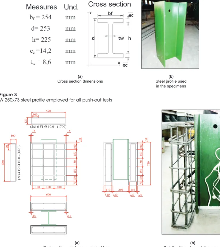
Three experimental specimens were built with Truss Connectors and three with Stud Bolt Connectors. For all specimens, the steel
profile employed was a W250x73, equivalent to the HEB 260 pro-file indicated by Eurocode 4 [9], as shown in Figure 3.
Table 4 presents the nomenclature and other details of the speci-mens analyzed in this work.
All specimens which constitute this experimental program contain reinforcement bars of the CA-50 specification with a 10.0 mm di-ameter. Figure 4 details the steel reinforcement utilized for the ex-perimental specimens evaluated.
Figure 5 shows details of the dimensions of the models and the
Figure 3
W 250x73 steel profile employed for all push-out tests
(a)
Cross section dimensions (a)
Design of the reinforcement steel bars
(b) Steel profile used
in the specimens
Figure 4
Experimental specimen slab reinforcement steel bars
(a)
Design of the reinforcement steel bars Details of the steel reinforcement (b)
660 100 570 120 (2x) 6 F1 Ø 10.0 - (1700) (2x) 4 F2 Ø 10.0 - (18 20) 750 150 150 150 100 70 100 180 180 180 100 150 150 150 100 70 110 20 260 20 110 20 20 15 600 15 15 15 30 100 100 30
Table 4
Push-out test summary
Type of specimens the specimensNames of Quantity of specimens Type of connector Diameter (ϕ)
S S19 3 Stud Bolt 19.0 mm
R R12.5 3 TR - Rectangular triangle truss 12.5 mm
(a)
Specimen details for the S type connectors (stud bolt)
Figure 5
Positioning of shear connectors and steel reinforcement bars in concrete slabs of specimens
(dimensions in milimeters)
660 100 570 120 (2x) 6 F1 Ø 10.0 - (1700) (2x) 4 F2 Ø 10.0 - (1820 ) 750 150 150 150 100 70 100 180 180 180 100 150 150 150 100 70 110 20 260 20 110 20 20 15 600 15 15 50 70 90 80 80 90 30 15 30 100 100 30 100 32 250 250 250 80 80 80 250 130 32 10 250 250 250 19 660 100 570 120 (2x) 6 F1 Ø 10.0 - (1700) (2x) 4 F2 Ø 10.0 - (1820) 750 150 150 150 100 70 100 180 180 180 100 150 150 150 100 70 110 20 260 20 110 20 20 15 600 15 15 50 180 70 180 85 30 15 30 100 100 30 231 250 269 250 250 250 100 40 135 130 180 35 35 180 35 35 250 250 160 160 (b)Specimen details for the TR shear connectors
placement of the steel reinforcement and shear connectors. In re-gards to Eurocode 4 [9], it should be noted that the length of the concrete slabs was increased by 10 cm just to accommodate the whole extension of the shear connectors.
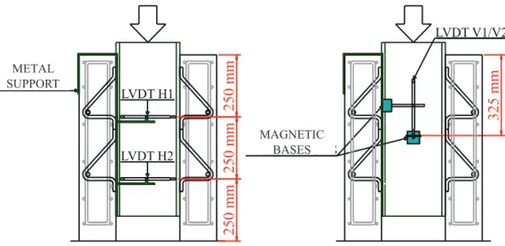
2.2.2 Vertical and horizontal displacements
The vertical displacements of slabs in relationship to the steel profile and the transversal spacings between slabs were monitored through LVDTs (Linear Variable Differential Transformers). The LVDTs were positioned in accordance with Figure 6. Two were placed horizon-tally for measuring the uplift, and two vertically for the monitoring of the displacements of the steel beams in relation to the concrete slabs. The horizontal LVDTs were fixed with the help of clamps and magnetic bases, while the vertical ones were put in place only using
the magnetic bases. The points of the two vertical LVDTs touched steel sheets fixed to magnetic bases, which were in turn fixed to the steel profiles of the models, and the points of the horizontal LVDTs were put in direct contact with the surface of the concrete slabs in a position perpendicular to the vertical axis of the specimens. The horizontal LVDTs were placed at the height of the upper verti-ces of the connectors, the higher one at a distance of 25 cm from the upper extreme of the slabs and the lower one 25 cm lower than the higher one’s axis. The vertical LVDTs were placed to mea-sure the vertical displacement of the steel profile in relation to the slabs, at a distance of 325 mm from the upper extreme of the slabs of each model. Figure 7 presents details of the positioning of the LVDTs in the experimental specimens.
2.2.3 Loads
The loads were applied to the steel profiles of the experimental specimens and transmitted to the slabs through the shear con-nectors. The values of the loads applied to the specimens were obtained through a Load Cell positioned in line with and above the Hydraulic Actuator. The applied loads were registered manually for all the load steps applied and then related to the values of vertical displacements (slide) and uplift for each model tested.
2.3.4 Test assembly
The test frame of the Structural Engineering Laboratory in the Civil Engineering Department of the University of Brasilia has a load capacity compatible with the push-out experiments. This frame, which is shared with other research projects, is 3.55 meters high, while the models are 80 centimeters tall. To enable the applica-tion of the loads to the specimens, concrete blocks were piled on top of each other, with a plaster layer between them, to promote an even contact between the surfaces and correction of eventual level differences (Cavalcante, 2010 [1]). A steel plate was placed over the last block, and the specimen to be tested set on the steel
Figure 6
Positioning of LVDTs
325 mm
LVDT V1/V2
BASES
MAGNÉTICAS
250 mm
250 mm
250 mm
LVDT H1
LVDT H2
SUPORTE
METÁLICO
SUPPORT METALMAGNETIC BASES
Figure 7
Positioning of horizontal and vertical LVDTs for the
push-out tests
plate, with both being set over plaster layers for the same reasons mentioned before.
Chains were employed surrounding the slabs of the specimens to preventing the falling of concrete slabs or large pieces of concrete debris at the moment of failure. Figure 8 presents details of the test system utilized, with the positioning of the specimens, the Hydrau-lic Actuator and the Load Cell on the reaction frame.
2.2.5 Data acquisition system
The displacement values obtained through the LVDTs were regis-tered for each load step, with the help of Spyder-8 Data Acquisition Modules and the Data Acquisition Software Catman Version 4.5. manufactured by the German company HBM (Hottinger Baldwin Messtechnik GmbH). The data was stored in the computer shown in Figure 9 (a), which also displays the Spyder-8 modules. Of the modules displayed in the picture, the one with eight channels was used for the 4 LVDTs employed in each test.
The load data acquisition was accomplished through direct reading of the values of a digital panel and manual annotation; values of loads at the failure and immediately afterward were registered through filming for all the push-out tests. The panel presents values of loads obtained through the Load Cell to which it is connected, with a load display of up to 2000 kN. The Load Cell was positioned in between the Hydraulic Actuator, which transmits the loads to the specimens, and the beam of the test steel frame, which offers the reaction to the force applied by the actuator. Figure 9 (b) details this assembly.
The loading was applied through an Electrical Hydraulic Pump shown in Figure 9 (b). This pump allows the application of the load with man-agement of the force, which is displayed on the digital panel.
3. Results and discussions
3.1 Push-out Tests
Specimens built with Stud Bolt and Truss connector made of bent 12.5 mm diameter rebars were subjected to push-out ex-perimental tests, with the intention of evaluating the potential of the Truss Connectors proposed in this work and establishing comparative analyses of the displacement results with the Stud Bolt Connector specimens.
The push-out tests were conducted considering the procedures
Figure 8
Test assembly for the push-out models
(a) Test frame – perspective view (b) Positioning of the specimens
Figure 9
Data acquisition system and hydraulic pumps for applying loads
(a)
detailed in Eurocode 4 [9], accepted as an international standard for the evaluation of new shear connectors for composite beams in a low cost, fast and reliable way.
The results of the push-out tests obtained for the experimental specimens built are presented next.
3.1.1 Failure loads and design strength
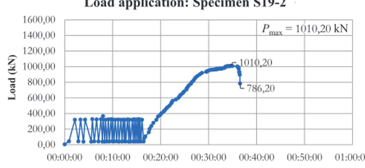
The load was applied to the experimental specimens through a
Hydraulic Actuator, connected to a Hydraulic Pump and positioned in line with a Load Cell, in accordance with the recommendations of Eurocode 4 [9]. Initially 25 cycles of loading were applied to the specimens, with loads varying from 40 to 320 kN for all specimens, which represents 5% to 40% of the estimated failure load for the experimental specimens tested, which was 800 kN for both Truss and Stud Bolt Connectors. Those loads were obtained through nu-merical studies carried out with the ANSYS Version 14.5 software. Figure 10 presents details of the load application on the specimens
Figure 10
Loads versus time results for stud bolts and truss connectors tested
(a)
Specimen 1 – Stud bolt connector
(c)
Specimen 3 – Stud bolt connector
(d)
Specimen 2 – Truss connector ϕ 12.5 mm
(b)
Specimen 2 – Stud bolt connector
(d)
Specimen 1 – Truss connector ϕ 12.5 mm
(d)
throughout the test, with Pmax being the maximum load reached for each specimen tested.
In accordance with Eurocode 4 [9] the experimental specimens must be taken to failure after the 25th loading cycle within a timeframe not
inferior to 15 minutes, from the load of 40% of the estimated failure load (320 kN) and that was accomplished for all six experimental push-out tests. The monitoring of the displacement values was not possible for the phase of unloading 20 % of the maximum load for specimen S19-1, with Stud Bolt Connectors, as may be observed in Figure 10 (a), because the failure for this specimen was instanta-neous, with a sudden fall of the acting load.
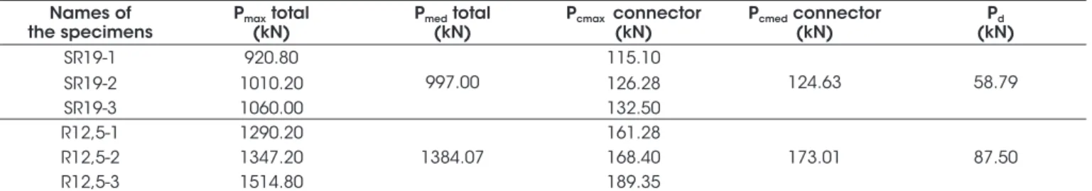
Table 5 presents the failure load values for all the specimens tested. The failure loads obtained for the six tests were higher than the estimated 800 kN for the connector configuration employed. The tests were considered valid, with no need to perform additional ones. This validation is in accordance with Eurocode 4 [9] which requires that the three maximum loads Pmax should not differ in more than 10% compared to the mean of the results for specimens with an identical design.
The European Standard Eurocode 4 [9] presents an expression, Equation 1, for the calculation of the design strength of the shear
connectors tested through push-out tests.
(1)
where:
fu is the minimum failure strength capacity of the connector material; fut is the actual failure strength of the connector material;
PRk is the minimum failure load of the tested models, divided by the number of connectors, reduced by 10%;
γv is the partial safety factor recommended to be 1.25 by the Eu-rocode 4 [9].
The design strength obtained through Equation 1 is for one shear connector. Using that equation, the values obtained for the design strength of the Stud Bolt Connector was 58.79 kN and for the Truss Connector with 12.5 mm diameter was 87.50 kN. Each push-out specimen was tested with eight connectors, so the design strength for the models with Stud Bolt Connectors was 470.32 kN, and for the specimens with Truss Connectors, 700 kN.
As was observed in Cavalcante (2010) [1], the failure of the Stud Bolt Connectors occurred on the metal base close to the welding region, without failure of the welding however, as determined by
Table 5
Failure loads for all specimens tested
Names of
the specimens Pmax(kN) total Pmed(kN) total Pcmax connector(kN) Pcmed connector (kN) (kN)Pd
SR19-1 920.80 997.00 115.10 124.63 58.79 SR19-2 1010.20 126.28 SR19-3 1060.00 132.50 R12,5-1 1290.20 1384.07 161.28 173.01 87.50 R12,5-2 1347.20 168.40 R12,5-3 1514.80 189.35
Figure 11
Analyses of the specimens after failure: (a) Typical longitudinal section of slab A of the S19-2 connector;
(b) Typical longitudinal section of slab B of the R12.5-2 connector; (c) Specimen R12.5: Slab-B after
concrete demolition; (d) Specimen S19-2: Slab-A after concrete demolition
Rupture and tension
Rupture at the base metal
(a)
AWS D1.1/D1.1M (2015) [14], with the separation of one of the slabs for each specimen tested. For the Truss Connectors, no fail-ure of the welding was observed. The failfail-ure of the Truss Con-nectors happened through tension in one of the legs of the Truss Connectors, with no separation of the slabs from the rest of the model. The cohesion of the parts of the specimens (slabs and steel profiles) was assured by one of the legs of each Truss Connec-tor, which remained complete after the experimental tests. In Truss Connectors, the failures took place in the vertical legs, in the region close to the shearing plane between the concrete slab and the flange of the steel profiles. Figure 11 presents details of the failure modes observed in the experimental models.
3.1.2 Vertical displacement
The vertical displacements (slip) between the steel profile and the concrete slabs of the specimens were monitored throughout the push-out tests through two LVDTs positioned symmetrically in rela-tion to the steel profile’s web. These LVDTs were named LVDT V1 and LVDT V2. The vertical displacements recorded by the LVDTs V1 and V2 are presented in Figure 12.
An analysis of the data of vertical displacements between steel profile and concrete slab was made to classify the connectors in regard to their ductility. Such classification is done considering the
load x displacement curves and measuring the displacements (slip) for the unloading of 20% of the failure load, but such displacement is only measured after failure. The procedure consists of obtaining the characteristic resisting load Puk, 10% lower than the maximum
load achieved and its corresponding vertical displacement (slip) (δu) obtained from the graph. According to Eurocode 4 [9], connec-tors that present characteristic displacement (δuk = 0.9.δu) higher than 6.0 mm in the push-out tests are classified as non-ductile. Both the Stud Bolt and the Truss Connectors presented δuk values higher than 6.0 mm and may be classified, therefore, as ductile. According to Eurocode 4 [9], ductile connectors with ideal plastic behavior, with plastic deformation, and good stress distribution in between connectors for service loads may be considered, in the design process. Figure 13 shows δu and δ80 values, obtained,
re-spectively, for 90% and 80% of the failure loads of each specimen. Table 6 presents the calculated values of δuk and the classification of the connectors with respect to their ductility, in accordance with Eurocode 4 [9] criteria.
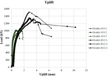
3.1.3 Transversal separation – uplift
For the monitoring of the transversal separation between slabs, the uplift displacement, two LVDTs were fixed to one slab and touch-ing the other slab, at two heights, to allow for the calculation of the
Figure 12
Average curves: vertical displacement vs applied load – for the specimens tested
(a)
Stud bolt connectors Truss connectors ϕ 12.5 mm(b)
Table 6
Classification of connectors according to their ductility
Type of the
connector Model (mm)δu (mm)δuk EN 1994-1-1:2004 [9]Classification Failure mode
Stud bolt
SR19-1 – – –
Rupture at the base metal
SR19-2 17.50 15.75 Ductile
SR19-3 18.60 16.74 Ductile
Truss connector with ϕ 12,5 mm
R12.5-1 25.75 23.18 Ductile Rupture of
connector vertical leg and concrete
R12.5-2 27.40 24.66 Ductile
Figure 13
Average curves: vertical displacement vs applied load for the specimens tested for the calculation of the
characteristic vertical-displacements (slip)
(a)
Specimen 1 – Stud Bolt
(c)
Model 3 – Stud Boltr
(e)
Model 2 – Truss connector ϕ 12.5 mm
(b)
Model 2 – Stud Bolt
(d)
Specimen 1 – Truss connector ϕ 12.5 mm
(f)
average displacement at the position of the centroid of the con-nectors. Figure 14 compares the average values of both horizontal LVDTs for each specimen tested.
The tests reveal that the LVDTs H1 and H2 registered close results for the separation of the slabs as the load increased, which leads to the conclusion that the horizontal separation between slabs hap-pened in a similar way at both positions. For the 12.5 mm diameter, the uplift for the Truss Connector specimens was higher. This higher uplift was in the lower part of the slabs for loads close to Pmax
(maxi-mum test load) and the load decline stage at the end of the tests. Figure 14 shows that Truss Connectors led to greater maximum loads and greater uplifts too, for each experimental specimen. In some structural situations, as in composite beams, besides the longitudinal shear forces, the connectors are also subject to forces perpendicular to the axis of the beam. Such forces tend to cause the separation of the concrete slab and the steel profile. Generally, these transversal forces are much lower than the longitudinal shear forces, and in prac-tical situations, it is not necessary to calculate them.
4. Conclusion
The push-out tests carried out in this research in accordance with the procedures established in Eurocode 4 [9] are internationally known, accepted, and largely utilized for the assessment of new types of shear connectors.
The push-out test applied to the proposed Truss Connectors fol-lowed the procedures established in Eurocode 4 [9]. The proposed connector, welded to the steel profile flange, is in the shape of a rectangular triangle, and made of CA-50 steel bar with a 12.5 mm diameter. The results from the push-out tests compared to the results of Stud Bolt Connectors (19.0 mm diameter) show that the Truss Connector has higher strength capacity. Moreover, the mate-rial of such connector is easily found and the fabrication process is widely known. Furthermore, the proposed connector conforms to the slip longitudinal displacement and uplift displacement between slab and steel profile, as specified by Eurocode 4 [9].
The push-out tests were conducted with the intent of characterizing the shear connectors studied as to their design strength capacity and ductility, in accordance with Eurocode 4 [9]. Thus, concerning the experimental tests, the following can be concluded:
n The maximum strength of the push-out specimens with 8 Truss Connectors showed, on average, is 1384.07 kN, which corre-sponds to 173 kN per connector. For the Stud Bolt Connectors the average of the maximum strengths is 997.00 kN, resulting in 124.63 kN per connector;
n The design resistance, determined according to the Eurocode 4 [9], resulted in a value of 62.45 kN per connector for the Stud Bolt and 87.50 kN per connector for the Truss Connector with 12.5 mm diameter rebar;
n The relief of load of 20% at the end of the tests was carried out for five specimens subjected to push-out tests, 3 of them with the Truss Connectors and 2 with the Stud Bolt. This data allowed the classification of both type of connectors as ductile. For this reason, they showed plastic behavior upon failure and adequate distribution of stresses between connectors for ser-vice loads;
n Truss Connectors made of steel bars 12.5 mm in diameter pro-vide higher strength and higher values of uplift in comparison to Stud Bolt Connectors;
n Upon failure, the Truss Connectors vertical leg tore out due to tension, but welding was kept intact between connectors´ legs and the steel profile flange. The failure of the Stud Bolt Connec-tors was observed at the welding region between connector and the steel profile flange showed rupture of the base metal.
5. Acknowledgments
The authors would like to thank the following companies: (a) CON-CRECON for the donation of all the concrete used in this research and (b) CPC ESTRUTURAS for the donation of all the steel pro-files and Stud Bolt Connectors employed during the push-out tests. The authors also want to express their gratitude to (1) CPNQ (The Brazilian National Council for Scientific and Technological Devel-opment), (2) CAPES (Coordination for the Improvement of Higher Level Education), for the research grants. Finally, the authors wish to thank the University of Brasília (UnB) for the use of its laborato-ries and facilities.
6. Bibliographic references
[1] CAVALCANTE, O. R. O. (2010). Estudo de Conectores de Cisalhamento do Tipo ‘V’ em Vigas Mistas. Tese de Dou-torado em Estruturas e Construção Civil, Publicação E.TD – 006/10, Departamento de Engenharia Civil e Ambiental, Universidade de Brasília, Brasília, DF, 192p.
[2] ASSOCIAÇÃO BRASILEIRA DE NORMAS TÉCNICAS. (2008). ABNT NBR 8800. Projeto e execução de estruturas de aço e de mistas aço e concreto de edifícios.
[3] CHAVES, I. A., (2009). Viga mista de aço e concreto consti-tuída por perfil formado a frio preenchido. Dissertação (Mes-trado-Programa de Pós-Graduação e Área de Concentração em Engenharia de Estruturas) – Escola de Engenharia de São Carlos da Universidade de São Paulo, 2009.
Figure 14
Curves of the average transversal separation
(uplift) vs applied load for the push-out tests
[4] VERÍSSIMO, G. S., (2007). Desenvolvimento de um co-nector de cisalhamento em chapa dentada para estruturas mistas de aço e concreto e estudo do seu comportamento. Tese de Doutorado em Estruturas, Escola de Engenharia, Universidade de Federal de Minas Gerais, 290p.
[5] REHMAN N., D. LAM, X. DAI, A.F. ASHOUR., (2016). Ex-perimental study on demountable shear connectors in com-posite slabs with profiled decking. Journal of Constructional Steel Research, 122. pp. 178–189.
[6] DAI X.H., D. LAM, E. SAVERI; (2015). Effect of concrete strength and stud collar size to shear capacity of demount-able shear connectors. Journal of Structural Engineering, American Society of Civil Engineers, 141.
[7] PATHIRANA S.W., B. UY, O. MIRZA, X. ZHU., (2015). Strengthening of existing composite steel concrete beams utilizing bolted connectors and welded studs. Journal of Constructional Steel Research, 114. pp. 417–430.
[8] BARBOSA, W. C. S., (2016). Estudo de Conectores de Cisal-hamento em Barras de Aço para Vigas Mistas de Aço e Con-creto. Tese de Doutorado em Estruturas e Construção Civil, Publicação E.TD – 008A/16, Departamento de Engenharia Civil e Ambiental, Universidade de Brasília, Brasília, DF, 511p. [9] EUROPEAN COMMITTEE FOR STANDARDIZATION (2004). 1994-1-1: Eurocode 4 - Design of composite steel and concrete structures; Part 1.1: General rules and rules for buildings. [10] ASSOCIAÇÃO BRASILEIRA DE NORMAS TÉCNICAS.
(2007). ABNT NBR 5739. Concreto – Ensaio de compressão de corpos de prova cilíndricos.
[11] ASSOCIAÇÃO BRASILEIRA DE NORMAS TÉCNICAS. (2008). ABNT NBR 8522. Concreto – Determinação do módulo estático de elasticidade à compressão.
[12] ASSOCIAÇÃO BRASILEIRA DE NORMAS TÉCNICAS. (2013). ABNT NBR ISO 6892-1. Materiais metálicos – Ensaio de Tração Parte 1: Método de ensaio à temperatura ambiente. [13] ASSOCIAÇÃO BRASILEIRA DE NORMAS TÉCNICAS.
(2007). ABNT NBR 7480. Aço destinado a armaduras para estruturas de concreto armado – Especificação.
[14] AWS D1.1/D1.1M (2015). Structural Welding Code – Steel. American Welding Society (AWS) D1 Committee on Struc-tural Welding.
[15] JOHNSON, R. P. (1994). Composite Structures of Stell and Concrete – Beams, Slabs, Columns, and Frames for Build-ings. Vol. 1, 2nd edition, Oxford (UK): Blackwell Science Ltd.
![Table 6 presents the calculated values of δ uk and the classification of the connectors with respect to their ductility, in accordance with Eurocode 4 [9] criteria.](https://thumb-eu.123doks.com/thumbv2/123dok_br/15232376.1022002/10.892.69.822.172.450/presents-calculated-classification-connectors-ductility-accordance-eurocode-criteria.webp)